ANTIFERENCE ATR269 User manual

PROFESSIONAL CABLE TESTER
USER GUIDE
ATR269


1
Specifications:
Name
Professional Cable Tester
Display
LCD Module (64 mm x 33 mm)
Connector
type
RJ45, RJ12 ( RJ11 ) & F connector
Button
(1) LAN . (2) TEL . (3) COAX . (4) TONE . (5) LENGTH .(6) TEST .
(7) POWER . (8) ▲. (9) ▼. (10) ◄. (11) ►. (12) MEMORY. (13) SETUP.
Cable type
Shielded or unshielded, CAT -5, CAT-6, CAT-7, coax cable
Error status
Open circuit, short circuit, cross circuit and split pairs
Measure
types
Measures cable length via TDR
Checks and verifies wire map
Generates two different tracing tones to help identify users
Cable length
& accuracy
Accuracy of the length measurement is ± 5 %
length: 1~350 meters (3~1200 feet)
Minimum
cable length
for testing of
split pairs
1 meter (3 feet)
Power source
9 Volt battery
Low battery indicator.
Turns off
automatically
Auto-off in any mode and low power consumption for long battery
life

2
Input
protection
Protection against excess voltage, transients ringer signal
Physical
Dimension
195 mm (L) , 90 mm (W) , 40 mm (H)
Environmental
Operating Temperature: 0° to 50° C ( 32° to 122° F )
Storage Temperature: -10° to 60° C (14° to 140° F )
Humidity: 10 % to 90 % non-condensing
Accessories
F to BNC Adapter * 2 pcs, 9 Volt battery * 2 pcs, RJ45/RJ11 Adapter
Belt Clip * 1pcs, BAG * 1pcs

3
Operation
*Press the POWER ON button, Start up screen
displays as below: Select required mode:
LAN Mode:
Press ▲▼ KEY to select which mode to
test then press TEST KEY to start testing.
LAN MODE has 2 modes –
MAIN to LOOPBACK & MAIN to REMOTE TERMINATOR.
(1). Testing from MAIN connector to LOOPBACK connector:
LAN cable connected from MAIN to LOOPBACK.
Test Functions:
(a). PASS, OPEN, SHORT, CROSS, SPLIT etc.
(b). Test FTP or UTP LAN cable.
(c). If display shows OPEN FAIL it will display the
distance from MAIN connector to the broken
point.
*LAN MODE testscreen as below:
Press LAN KEY or TEST KEY to start test.
Test Result:
*If LAN cable is wired correctly, display will show PASS as below:
Press▲ KEY to return to the main menu.

4
●FTP : Shielded : UTP : Unshielded.
●0 : Shielded.
●LOOP: LAN cable connected from MAIN connector to LOOPBACKconnector.
●REMOTE: LAN cable connected from MAIN connector to remote terminator
connector.
* If cable is OPEN circuit or disconnected, the display shows FAIL as below:
●Display shows the OPEN LAN cable pair‘s distance from MAIN connector to
broken point, and the open pair’s numbers will blink.
* If there is a short, display shows FAIL SHORT as below:
* If there is a cross wire, display shows FAIL CROSS as below:
●The short pair’s numbers will be blink.
●The CROSS cable’s numbers will be blink & will show the incorrect cable wiring.
* If LAN cable is SPLIT, the display shows FAIL as below:
●The SPLIT cable’s numbers will blink.

5
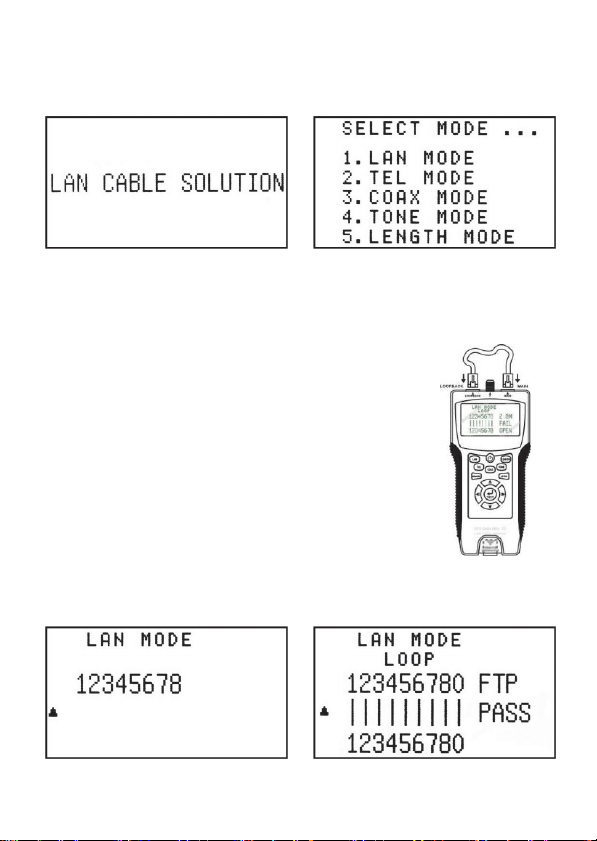
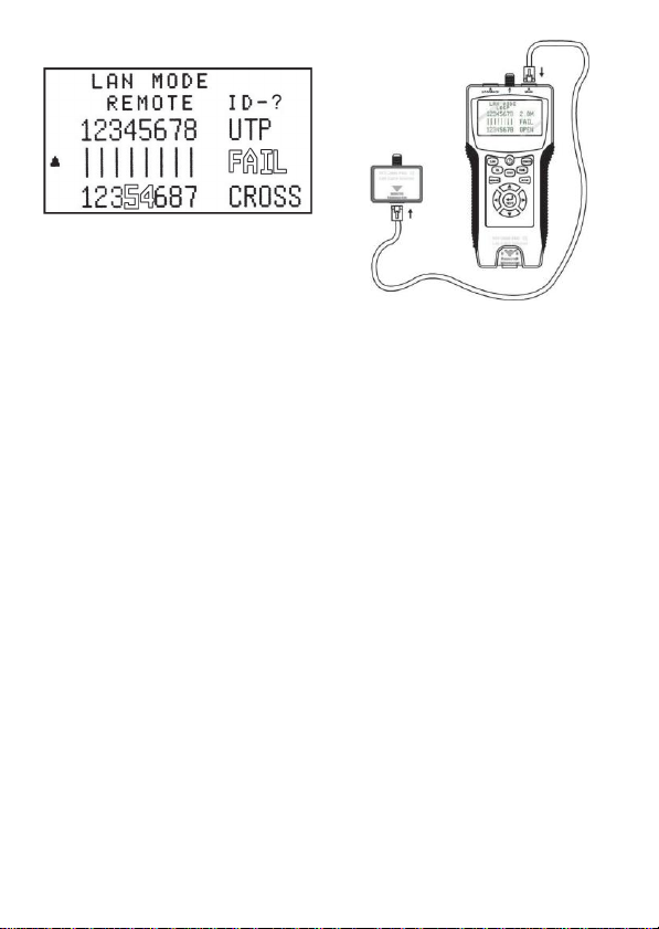
(2). Testing from MAIN connector to REMOTE terminator:
LAN cable should be connected from MAIN to REMOTE
terminator.
Test Function:
(a). Displays PASS, OPEN, SHORT, CROSS etc.
(b). Test FTP or UTP LAN cable.
(c). When display shows OPEN FAIL, it displays the distance from
the MAIN connector to the broken point.
Press LAN KEY or TEST KEY to start test.
Test Result :
* If LAN cable is wired correctly, display will
show PASS as below:
●Display also shows the remote terminator ID
(for example: ID-1) and beeper will sound.
* If the cable is OPEN circuit, display shows FAIL as below:
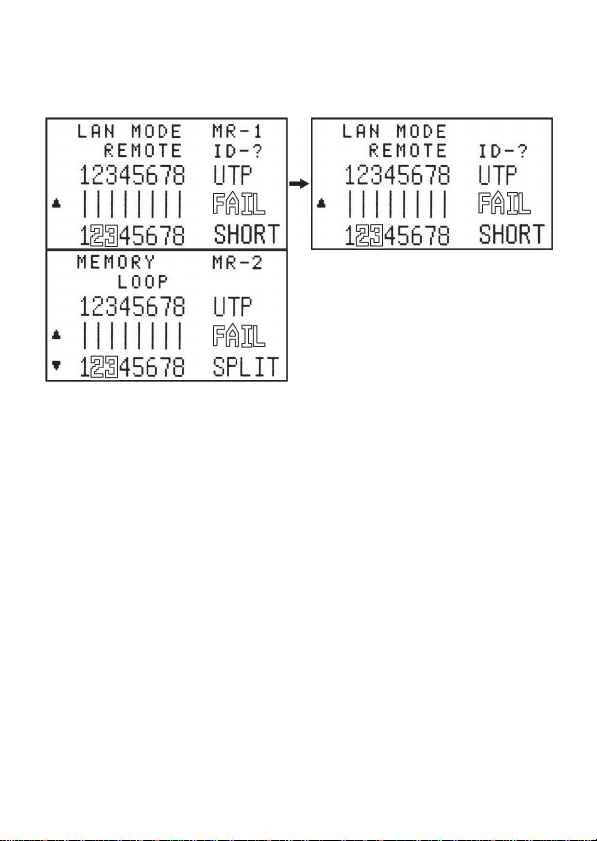
* If there is a SHORT, display shows FAIL as below:
●Display shows the OPEN LAN cable pair’s distance from MAIN
connector to broken point and the open pair’s numbers will blink,
Display ID-? .
●The short pair’s numbers will blink.

6
* If LAN cable is CROSS display shows FAIL as below:
●The CROSS cable’s numbers will blink
showing incorrect cable arrangement.
(3). Memory function in the LAN Cable Test Mode
It is possible to memorize up to 8 results of a LAN cable test.
(a). Press the MEMORY KEY to memorize the result of the LAN cable test.The
LCD screen will briefly display MR-1 to indicate the results have been saved
and then will return to the result of the current test. A total of8 sets of test
results can be stored in LAN cable test mode.
(b). When the MEMORY KEY is pressed again, it will memorize the next result
and the LCD screen will display MR-2 briefly indicating the next memory setting
has been used before returning to the result of the current test.

7
(c). Once MR-8 is reached, all memories are full and no further test results
may be saved.
Reviewing the Memories.
(a). To enter memory mode press and hold the MEMORY KEY for 3 seconds
until the memory menu is displayed on the LCD screen.
(b). Press the ▲▼ Key to select the required memory.

8
Erasing Memories.
(a). Enter memory mode by pressing the MEMORY KEY for 3 seconds.
(b). Press the TEST KEY to enter the erase function.
Clearing ALL memories:
Press ◄ Key to clear ALL memories. The LCD screen will display MR-0
indicating no memories are saved.
Return to main menu:
Push ► Key to go back and NOT erase ALL memories. Press a cable mode
button to continue testing.
(4). When the battery voltage drops below 6.0V the low battery indicator will blink.
Please replace battery.
The battery icon will blink when the
battery needs replacing.

9
TEL Mode :
TEL MODE has 2 modes –
MAIN to LOOPBACK & MAIN to REMOTE TERMINATOR.
1. Testing from MAIN connector to LOOPBACK connector:
Connect TEL cable from MAIN to LOOPBACK.
Test Functions:
(a). PASS, OPEN, SHORT, CROSS, SPLIT etc.
(b). If display shows OPEN/SHORT FAIL it will
display the failed pin(s).
●To select the type of TEL cable press ▲▼ key in TEL MODE,
●Then press the TEL key or TEST key to start the test.
When the test is complete the results will be displayed on the screen as below:
In the case of a PASS:
TEL (6C` 4C` 2C) results are displayed as below:

10
In the case of an OPEN FAIL:
If the display shows OPEN FAIL then there is an open circuit and the message
will display as below and the indicated pin number will blink.
In the case of a SHORT FAIL.
If the display shows SHORT FAIL then there is a short circuit and the message
will display as below and the indicated pin number will blink.
In the case of a CROSS FAIL.
If the display shows CROSS FAIL then there is a cross wire and the message will
display as below and the indicated pin number will blink.

11
2. Testing from MAIN to REMOTE TERMINATOR:
Connect TEL Cable between MAIN & TERMINATOR.
●To select the type of TEL cable by Press ▲▼ key in TEL MODE. Then press the
TEL Key or TEST key to begin the test.
When the test is complete, the results will be displayed on the LCD screen.
In the case of a PASS; the result will be as below:
In the case of an OPEN FAIL; the result will be as below and any failed pins will blink.
PAS
S
PAS
S

12
In the case of a SHORT FAIL.
If the display shows SHORT FAIL then there is a short circuit and the message
will display as below and the indicated pin number will blink.
In the case of a CROSS FAIL.
If the display shows CROSS FAIL then there is a cross wire and the message will
display as below and the indicated pin number will blink.
(5). Memory function in the TEL Cable Test Mode
It is possible to memorize up to 8 results of a TEL cable test.
(d). Press the MEMORY KEY to memorize the result of the TEL cable test. The
LCD screen will briefly display MR-1 to indicate the results have been saved
and then will return to the result of the current test. A total of8 sets of test
results can be stored in TEL cable test mode.
(e). When the MEMORY KEY is pressed again, it will memorize the next result
and the LCD screen will display MR-2 briefly indicating the next memory setting
has been used before returning to the result of the current test.

13
Reviewing the Memories.
(c). To enter memory mode press and hold the MEMORY KEY for 3 seconds
until the memory menu is displayed on the LCD screen.
(d). Press the ▲▼ Key to select the required memory.
Erasing Memories.
(c). Enter memory mode by pressing the MEMORY KEY for 3 seconds.
(d). Press the TEST KEY to enter the erase function.
Clearing ALL memories:
Press ◄ Key to clear ALL memories. The LCD screen will display MR-0
indicating no memories are saved.
Return to main menu:
Push ► Key to go back and NOT erase ALL memories. Press a cable mode
button to continue testing.

14
COAX Mode :
COAX cables can only be tested from MAIN connector to REMOTE
terminator connector.
Test Functions :
(a). PASS、OPEN、SHORT etc. Display FAIL .
(b). When display shows OPEN FAIL, the distance fromMAIN
connector to broken point will be shown.
* COAX MODE shows initial display as below:
* Press COAX KEY or TEST KEY to start test.

15
Test Result :
* If COAX cable is correctly connected, the display shows PASS as below:
* If COAX cable is OPEN, the display will show FAIL as below:
* If COAX cable is SHORT, the display will show FAIL as below:
(6). Memory function in the COAX Cable Test Mode
It is possible to memorize up to 4 results of a COAX cable test.
(f). Press the MEMORY KEY to memorize the result of the COAX cable test.
The LCD screen will briefly display MR-1 to indicate the results have been
saved and then will return to the result of the current test. A total of 4 sets of test
results can be stored in COAX cable test mode.
(g). When the MEMORY KEY is pressed again, it will memorize the next result
and the LCD screen will display MR-2 briefly indicating the next memory setting
has been used before returning to the result of the current test.

16
. Reviewing the Memories.
(e). To enter memory mode press and hold the MEMORY KEY for 3 seconds
until the memory menu is displayed on the LCD screen.
(f). Press the ▲▼ Key to select the required memory.
Erasing Memories.
(e). Enter memory mode by pressing the MEMORY KEY for 3 seconds.
(f). Press the TEST KEY to enter the erase function.
Clearing ALL memories:
Press ◄ Key to clear ALL memories. The LCD screen will display MR-0
indicating no memories are saved.
Return to main menu:
Push ► Key to go back and NOT erase ALL memories. Press a cable mode
button to continue testing.

17
Tone Mode:
In order to detect a cable’s broken point,
the cable tester can transmit an audio
frequency and then a probe may be
used to determine the exact location.
Press TONE KEY and the display shows
as below:
●Press ◄ ► KEY to select which pair the TONE output signal will transmit from.
1 indicates TONE signal output transmits on pair 1. Press ►KEY to select the
next pair and repeat for all required pairs.
●Press ▲▼ KEY to select a different TONE audio frequency.
Note that there is no memory function for TONE MODE.
Length Mode:
Length Mode is used by connecting a cable from MAIN connector to open (DO
NOT use the remote terminator).
Test Functions:
(a). LENGTH mode can measure the Length of LAN cable or COAX cable.
(b). Memories may be used to record the data of a test result.
(c). SETUP mode allows the user to calibrate the tester if there is an error in
the test result.

18
Calibration can be carried out in either LAN or COAX mode.
(refer to SETUP MODE for this operation).
1. Testing LAN cable length: connect a LAN
cable connected from MAIN connector to
open.
Press LENGTH KEY and display will show as below:
●Push LENGTH KEY or TEST KEY to startthetest.
* Testresults will display as below:
●Press ▲ KEY to return to the previous screen.
●Press ◄ ► KEY to select the test result of the other pair’s lengths.
●Press ▼ KEY to select the length measurement of a COAX cable.
* If the LAN cable is connected from MAIN connector to REMOTE terminator.
* the display will show “Keep OPEN” as below:
Table of contents