PDi CT340 User manual
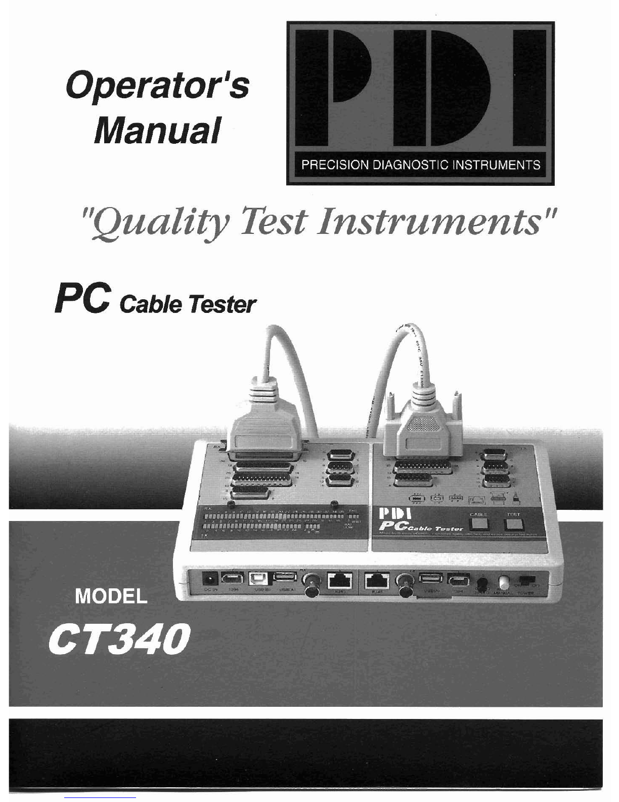
Operator
Manual
"QualityTestInstruments"
PC
Cable
Tester

ModelCT340 PC Cable Tester isa stand-alone test device; itis designed test the
mostcommon PCdata cables currently used. The CT340 tests wire connection
status for opens, shorts, cross wires, miss-wires and continuity. It is an invaluable
toolfor mostcable dealers, cable assembly house or system integrators to quickly
check the pin configuration or trouble shooting inany work environment.
Can test the most used PC data cables, network cables such as printer cable,
monitor cable, modem cable, mouse extensioncable, game cable, (USBand
1394cables arefor optional advancedmodel), BNC coax cable, RJ45cable etc.
for open, shorted miswire, continuity and pin configuration.
Enhanced
LED
glow for shorted printer cable test
Auto and manual scans can be selected
DCbattery compartment and AC power adapter jack provided
Handy held, easy access, simple installationand operation
I.RX SIDE CENTRONIC36PIN(F)
2 RX SIDE DB 25PIN (F)
3 RX SIDE DB 25PIN (M)
4
RX SIDEDB 15PIN (F)
5. RX SIDE
DB 9PIN (F)
6
RX SIDE DB 9PIN (M)
7.
RX SlDE DB 15PIN (F)
8.RXSIDE PIN-OUT INDICATOR
9. TX SIDE DB 25PIN
(F)
I0
TX
SlDE DB 25PIN(M)
11 TXSlDE DB 15PIN (M)
12 TX SIDE DB 9 PIN (F)
13 TX SIDE DB 9PIN (M)
14 TX SIDEHOB 15PIN (M)
15. TXSIDE PIN-OUT INDICATOR
16.CABLE TYPE FOR4 PIN
(1
-4 PIN)
17 CABLE TYPE FOR 1-9 PIN
18 CABLE TYPE FOR 1-15 PIN
19. CABLE TYPE FOR 1-25-36 PIN
20 BATTERY LOWINDICATOR
21
TX
SIDE GNDINDICATOR
22. RX SIDE GNDINDICATOR
23. CABLE TYPESELECTORKEY
24 TESTKEY
25. POWER ON/OFFSWITCH
26.AUTO/MANUAL SELECTOR
27. LEDINDICATORSPEED SWITCH
28.
TX
SIDE 1394CONNECTOR
29 TXSIDEUS6 (A) TYPE CONNECTOR
30. TX SlDE BNC CONNECTOR
31
TX
SIDE 8P8CRJ45JECK
32 RX SIDE 8P8CRJ45JECK
33 RX SIDEBNC CONNECTOR
34 RX SIDE US6 (A) TYPE CONNECTOR
35 RX SlDEUS6 (6) TYPE CONNECTOR
36 RX SlDE 1394CONNECTOR
37. 9VDC 150mA 2.5OPOWERJACK
(
Fig.
1
)
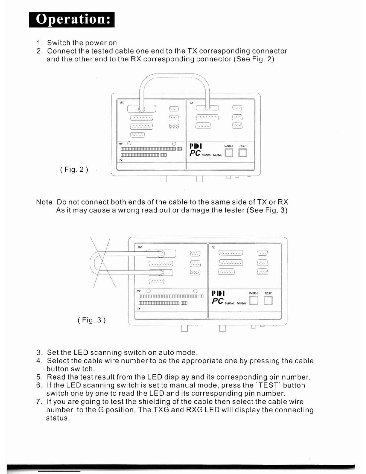
1. Switch the power on
2.
Connect the tested cable one end to the TX corresponding connector
and the other endto the RX corresponding connector (See Fig.
2)
(
Fig.
2
)
!_li
2
Note: Donot connect both ends of the cableto the same side of TX or RX
As itmaycause awrong read out or damagethe tester (See Fig. 3)
(Fig.3)
I
I
-
Ji
U
U
L:-
-
3.
Set the LED scanning switch on auto mode.
4.
Select the cable wire number to bethe appropriate one by pressing the cable
buttonswitch.
5.
Readthe test result from the LED display and its corresponding pin number.
6.
Ifthe LED scanning switch is set to manual mode, pressthe 'TEST' button
switch one byone to read the LED and its corresponding pin number.
7.
Ifyou are going to test the shielding of the cable then select the cable wire
number to the
G
position.The TXG and RXG LED will display the connecting
status.
Explanationfor LEDsdisplay:
(See
Fig. 4)
RXb
oi
u
i
I
TX~b~bob
135
~x,uiofioi
135
Txoaoilii
135
wlre no
3
opened wlre no.2
stralght connected wire no.586shorted
(
Fig.
4
)
1.
The tester will always send asignal from the TX side, in order, and the LEDsin
the TX side hasto beglowed byeach pin. Ifany LED on the TX side isnot
glowed thenthe LEDisdamaged.
2.
The tester can not tell you which endthe problem is coming from.
3.
Ifthe gender of the tested connector can notmatch together, a mini gender
changer is recommended to be used.
4. To save battery power don'tforget to turn the powerswitch off ifyou are not
going to operate it for awhile.
Table of contents
Popular Cable Tester manuals by other brands

IDEAL
IDEAL LT 8000 series Quick reference card

PCE Instruments
PCE Instruments CableTool user guide

JDS Uniphase
JDS Uniphase Testifier user guide

Black Box
Black Box TS940A-R2 Specifications

Hoyt Electrical Instrument Works
Hoyt Electrical Instrument Works 185 LST quick start guide

Black Box
Black Box TS510A-R2 Specifications


