Antrax SeriBox User manual

antrax Datentechnik GmbH
SeriBox
SeriBox
- Interface box with serial or USB interface
- PC connection / Read IN and OUT signal information
- x INput (TTL level / floating contact)
- x OUTput (relay contact)
Manual
Firmware V2.1 - 22.08.2008

antrax Datentechnik GmbH
[email protected] - www.antrax.de
Contents
General .................................................................................................
Using the SeriBox ................................................................................
Scope of delivery .................................................................................... 4
Hardware ........................................................................................... 4
Technical Features .................................................................................. 4
General ............................................................................................. 4
Power Supply ...................................................................................... 4
Input circuit ....................................................................................... 4
Output circuit ..................................................................................... 5
Interface ............................................................................................ 5
CE-Marking ........................................................................................ 5
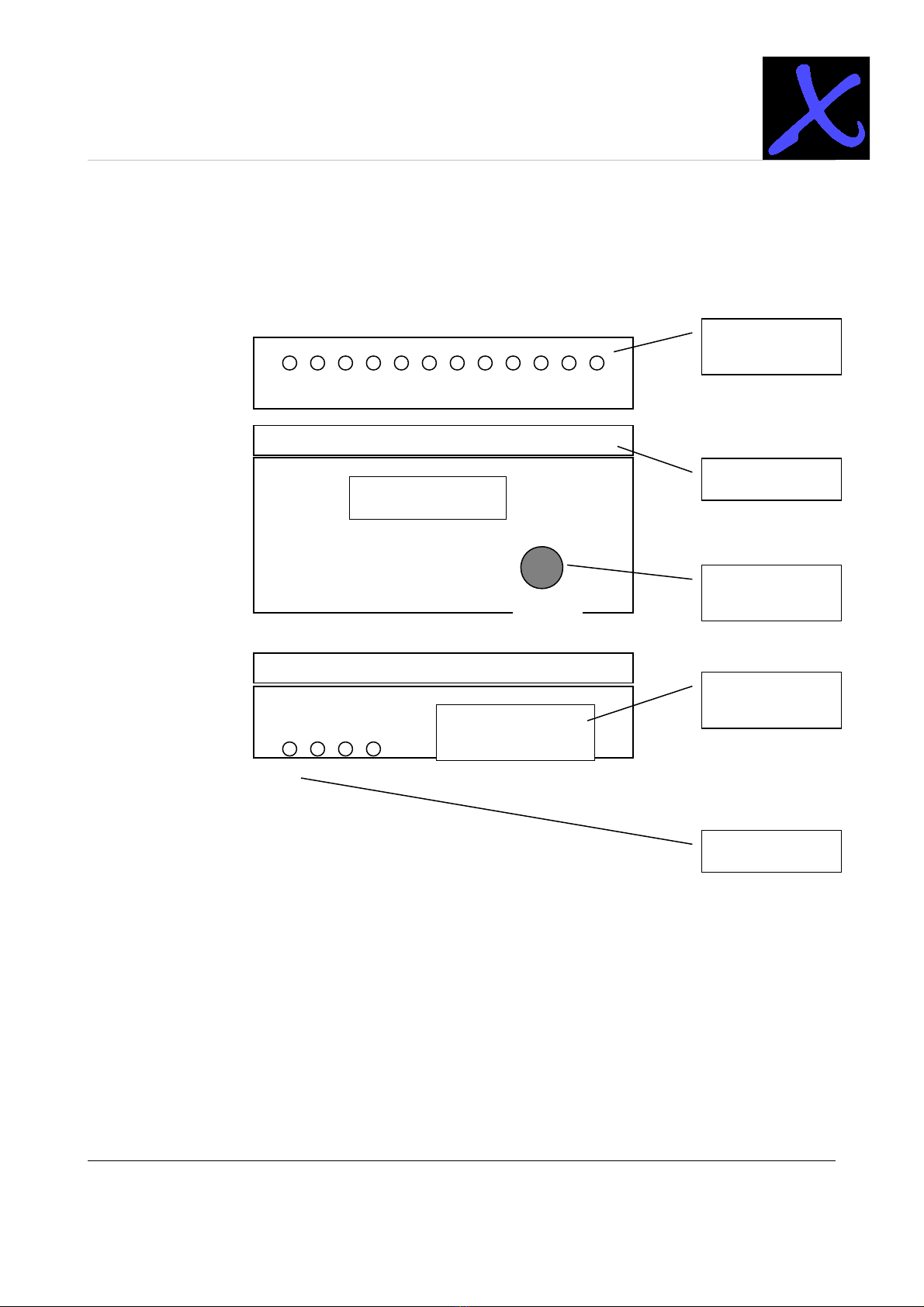
Screw clamp connections ......................................................................... 6
Srew clamp connections .......................................................................... 8
INputs ............................................................................................... 8
OUTputs ............................................................................................ 8
Supply voltage .................................................................................... 9
Serial interface ................................................................................... 9
Operation .............................................................................................. 9
General ............................................................................................. 9
Installation ....................................................................................... 10
Initial operation ................................................................................. 10
Installation .......................................................................................... 11
Control by PC software ....................................................................... 11
Parameter ........................................................................................ 12
General command processing ................................................................. 14
Commands ....................................................................................... 14
- 2 -
Hasenbrink 4, 2052 Herford, Germany Tel. +49 (0) 5221 929660 Fax +49 (0) 5221 9296628

antrax Datentechnik GmbH
[email protected] - www.antrax.de
General
The SeriBox is connected to a serial interface (RS-2 2) and allows switching ON and OFF of
three low-power relays or reading of three digital signals (TTL level or any floating contact) on
this interface.
Before first use of the SeriBox, please read this instruction manual carefully. It contains
information for the correct use and contains important tips for the installation of the SeriBox.
The manufacturer does not accept any liability due to improper use of the unit. In this case all
guarantee claims are invalid.
Using the SeriBox
The SeriBox is designed for
•for switching of resistive loads up to a maximum current of 1000mA at a maximum
voltage of 24V per output
•detection of switching states with TTL level or floating switches
in dry, closed residential and office workplaces, or control cabinets. Rules and regulations
governing the connection and use of electronic devices and their security regulations must be
followed.
Safety Instructions
Only use the SeriBox indoors and do not subject the unit to moisture or humidity.
Only clean the exterior of the SeriBox with a dry cloth.
Only load the output circuits of the SeriBox to their mentioned capacity limits.
An overload can lead to the SeriBox being destroyed.
Do not use the SeriBox in areas used by children.
Do not use the SeriBox if one or several parts (case, cable, plug) are damaged
or damage may be caused by its location (e.g. falling down).
The SeriBox may only be repaired by authorized service personnel.
Only connect electrical appliances that have no limit to their switched-on time (i.e. all
connected electrical appliances must be able to take continuous current without
sustaining damage in the case of a default to the permanently "ON" position.).
- -
Hasenbrink 4, 2052 Herford, Germany Tel. +49 (0) 5221 929660 Fax +49 (0) 5221 9296628

antrax Datentechnik GmbH
[email protected] - www.antrax.de
Scope of delivery
ardware
Everything there? Delivery of a SeriBox unit contains:
•the SeriBox
•optional: power supply
•optional: connector plug
•this manual
Technical Features
General
•Protective Class: IP20, only in dry rooms
•the current switching state of the IN- and OUTputs are signalled by green or yellow
LEDs
•optional: integrated signal button
•top-hat rail housing, width 4M (= 71mm), colour grey
•all connections via screw clamp connections or SUB-D
•Ambient temperature 0 ... +40°C
•Storage temperature -10 ... +70°C
•UL-listed:
•housing (NORYL UL 94 V-0)
•Relay (Meder, UL listed)
•PCB (FR4, 94 V-0)
•Standard components
Power Supply
•Power supply: 7...24 VDC, connection via screw clamps 21+22 (see below)
•Output voltage: 5 VDC, connection via screw clamps 2 +24 (optional, see below)
Input circuit
•Connection via screw clamps 1+2, +4 and 5+6
•Option 1. : Control by remote TTL level (1 = signal-plus, 2 = GND)
•Option 2. : Via floating contact (1 = signal, 2 = GND), Signal input is used for remote
switching on GND potential
•Switching state is signalled via green LED for each channel
- 4 -
Hasenbrink 4, 2052 Herford, Germany Tel. +49 (0) 5221 929660 Fax +49 (0) 5221 9296628

antrax Datentechnik GmbH
[email protected] - www.antrax.de
Output circuit
• individual OUTput circuits (connections via screw clamps 7+8, 9+10 and 11+12)
•Maximum switching capacity: 10W
•Maximum switching voltage: 200VDC
•Maximum switching current: 1000mA
•Switching state is signalled via yellow LED for each channel
Interface
•Serial interface (RxD, TxD, GND), 9600,8,N,1 - no handshake
•9pol.-SUB-D - connector (male, standard configuration)
•Connection to PC via standard extension or connection lead
CE-Marking
In accordance with the Low Current and EMV Guidelines.
- 5 -
Hasenbrink 4, 2052 Herford, Germany Tel. +49 (0) 5221 929660 Fax +49 (0) 5221 9296628

antrax Datentechnik GmbH
[email protected] - www.antrax.de
Screw clamp connections
- 6 -
Hasenbrink 4, 2052 Herford, Germany Tel. +49 (0) 5221 929660 Fax +49 (0) 5221 9296628
1 2 3 4 5 6 7 8 9 10 11 12
21 22 23 24
9pol. SUB-D
IN- and OUTputs
Si nal button
(only optional)
Serial interface
Power supply
Si nal lamps
TEST
SeriBox

antrax Datentechnik GmbH
[email protected] - www.antrax.de
Upper row of contacts, numbering from left to right:
Contact Description
1 Input 1: Signal
2 Input 1: GND
Input 2: Signal
4 Input 2: GND
5 Input : Signal
6 Input : GND
7 Output circuit 1 (potential free): 1A
8 Output circuit 1 (potential free): 1B
9 Output circuit 2 (potential free): 2A
10 Output circuit 2 (potential free): 2A
11 Output circuit (potential free): A
12 Output circuit (potential free): A
- 7 -
Hasenbrink 4, 2052 Herford, Germany Tel. +49 (0) 5221 929660 Fax +49 (0) 5221 9296628

antrax Datentechnik GmbH
[email protected] - www.antrax.de
Screw clamp connections
INputs
The Inputs 1 – on the contacts 1+2, +4 and 5+6 can be operated in two different modes:
-Control via remote TTL level (control as for example for a 5V electroluminescent
diode)
-via a floating contact (e.g. the signal input is remotely drawn to GND potential)
The relevant distinction is done automatically, no additional settings have to be executed.
OUTputs
The outputs consist of a floating relay contact. Please note that power shall never exceed a
value of 1000mA.
Caution: Also switching of 'harmless' signal circuits, may cause large current pikes, when for
example capacitors are loaded/unloaded. There is a risk of melting of the relay contacts, that
then can not open any more!
Lower row of contacts, Numbering from left to right:
Contact Description
21 Supply voltage: +7...24V (Input)
22 Supply voltage: 0V
2 Output voltage: +5V (optional)
24 Output voltage: 0V (optional)
Connector Description
SUB-D,
9pol.,
male
Serial interface
- 8 -
Hasenbrink 4, 2052 Herford, Germany Tel. +49 (0) 5221 929660 Fax +49 (0) 5221 9296628

antrax Datentechnik GmbH
[email protected] - www.antrax.de
Supply voltage
The supply voltage may vary in the range of 7...24V (DC), whereas smaller values should be
favoured. A supply voltage of 9V or 12V is recommended.
Serial interface
For connecting the SeriBox to a PC a standard extension or connection lead shall be used.
Operation
General
The SeriBox is connected to a serial interface (RS-2 2) and allows switching ON and OFF of
three low-power relays or reading of three digital signals (TTL level or any floating contact) on
this interface.
Control through PC is done with clear text command (interface parameter: 9600,8,N,1) so
any standard terminal program can be used for operating the SeriBox. For easy control you
also may want to use the AntraxServiceSoftware (ASS.EXE), that you can easily download
from our website (www.antrax.de/de/ass.html).
Changes to the inputs or pushing of the signal button are reported to the PC.
Behaviour of the SeriBox may be largely determined by means of parameters. These
settings are stored in the internal, non volatile configuration memory.
- 9 -
Hasenbrink 4, 2052 Herford, Germany Tel. +49 (0) 5221 929660 Fax +49 (0) 5221 9296628

antrax Datentechnik GmbH
[email protected] - www.antrax.de
Installation
Initial operation
Action Reaction
Install all cabling (supply
voltage, input signals, output
signals)
Switch ON supply voltage Starting sequence:
-the LED will flash in sequence from left
to right
-after that all LEDs flash one time
-optionally (parameter 2) all outputs
remain switched OFF or are set back to
the last switching state before power-
OFF
-optionally(parameter ) the start intro is
sent via the serial interface
Commands and parameters can
be set
Changes to the inputs Optionally (parameter 1) all changes to the
inputs via the serial interface are reported with:
INP1=0
INP1=1
INP2=0
INP2=1
INP =0
INP =1
When confirming with the integrated button the
SeriBox reports with:
BUTTON=0
BUTTON=1
- 10 -
Hasenbrink 4, 2052 Herford, Germany Tel. +49 (0) 5221 929660 Fax +49 (0) 5221 9296628

antrax Datentechnik GmbH
[email protected] - www.antrax.de
Installation
Control by PC software
For controlling the SeriBox any terminal program or own software may be used, as long as it
can output clear text to the used serial interface.
Following we describe control of the SeriBox with the supplied Windows "HyperTerminal":
•start "HyperTerminal" ("Accessories" "Communication" "HyperTerminal")→ →
•type in you requested name for the following set-up (e. g. "SeriBox") and choose
symbol
•for ''connect via'' type in the used interface (e. g. COM1)
•for ''connection settings'' please type in as follows:
Bits per second: 9600
Data bits: 8
Parity: none
Stoppbits: 1
Flow control: none
•then choose ''Settings'' "ASCII-Configuration" and confirm "Upon receiving set→
linefeed at the end of line" (otherwise all reports of the SeriBox are displayed in the
same line)
•press OK to go back
•with the first typed in letter (e. g. a "?") connection to the SeriBox is set up
•Please note: If the above settings shall be changed, please make sure to switch to
'offline' first (via the disconnect button)
- 11 -
Hasenbrink 4, 2052 Herford, Germany Tel. +49 (0) 5221 929660 Fax +49 (0) 5221 9296628

antrax Datentechnik GmbH
[email protected] - www.antrax.de
Parameter
Behaviours of the SeriBox can be set with the following parameters:
Parameter Function
SET1 = 0/1 ON/OFF switching of automatic change messages
If 1:
With changes to the inputs INP1 ... INP the SeriBox reports
the corresponding changes with:
INP1=0
INP1=1
INP2=0
INP2=1
INP =0
INP =1
With pressing of the integrated button the SeriBox reports
with:
BUTTON=0
BUTTON=1
SET2 = 0/1 Output-Restore after PowerON
If 1:
The SeriBox switches back to the last switching state after a
Power-ON
SET = 0/1 Output of the intros after PowerON
If 1:
The SeriBox reports for duty after Power-ON with the following
intro:
SeriBox (V2.0)
--------------
INP1=0
INP2=0
INP =0
OUT1=0
OUT2=0
OUT =0
BUTTON=0
- 12 -
Hasenbrink 4, 2052 Herford, Germany Tel. +49 (0) 5221 929660 Fax +49 (0) 5221 9296628

antrax Datentechnik GmbH
[email protected] - www.antrax.de
Automatic change report - SET1=0
Output-Restore after PowerON - SET2=1
Intro after PowerON - SET =1
with echo - SET4=0
Reset-downtime - SET5=5
OK
whereas the current values and parameter are shown.
SET4 = 0/1 with echo
If 1:
Echo function ON for signals via the serial interface.
SET5 = n Reset-downtime in seconds
See command OUT, valid range:
1 ... 60 seconds
- 1 -
Hasenbrink 4, 2052 Herford, Germany Tel. +49 (0) 5221 929660 Fax +49 (0) 5221 9296628

antrax Datentechnik GmbH
[email protected] - www.antrax.de
General command processing
Commands
The SeriBox can be controlled via the following commands:
Command
(affecting
outputs)
Function
OUTn =
0/1/R/P
OUT 1 = 0
OUT 2 = 1
OUT = R
OUT 1 = P
OUT x = 0
OUT x = 1
Switches the specified output (1 ... or all at same time)
●one
●OFF
●reset
●pulse
Examples:
switches OFF output 1
switches ON output 2
triggers a reset impulse at output (always specifies one single
output, you cannot specify ''x''!)
This command switches the specified output for the ''reset
downtime'' (= parameter 5) specified period in the respectively
other switching state and backwards.
Triggers a impulse at output 1 (always specifies one single output,
you cannot specify ''x''!)
This command switches on the specified output for 0,5 seconds
(= impulse length 500 ms) and back OFF. The impulse length
cannot be changed.
switches OFF all outputs
switches ON all outputs
- 14 -
Hasenbrink 4, 2052 Herford, Germany Tel. +49 (0) 5221 929660 Fax +49 (0) 5221 9296628

antrax Datentechnik GmbH
[email protected] - www.antrax.de
Command
(affecting
outputs)
Function
? Query of current switching state of all inputs and outputs with
following report (depending on the switching state):
INP1=0
INP2=0
INP =0
OUT1=0
OUT2=0
OUT =0
BUTTON=0
OK
{+}GET Complete query of all switching states and and query of all
parameters:
SeriBox (V2.0)
--------------
INP1=0
INP2=0
INP =0
OUT1=0
OUT2=0
OUT =0
BUTTON=0
Automatic change report - SET1=0
Output-Restore after PowerON - SET2=1
Intro after PowerON - SET =1
with Echo - SET4=0
Reset-downtime - SET5=5
OK
- 15 -
Hasenbrink 4, 2052 Herford, Germany Tel. +49 (0) 5221 929660 Fax +49 (0) 5221 9296628

antrax Datentechnik GmbH
[email protected] - www.antrax.de
Following applies at command handover tot he SeriBox, please note:
•Spaces are ignored
•Upper and lower case are not distinguished
•Each command must at least end with CR (character 1 )
•All parameters remain unchanged unless their are explicitly set anew
•All parameters are stored in a non-volatile configuration memory and also ''survive'' a
power failure
•recognised commands are confirmed with CRLF + 'OK' + CRLF
•not recognised commands are confirmed with CRLF + '?' + CRLF
•before sending a command the previous command must have been recognise and
confirmed by the SeriBox (confirmation or wait-time)
- 16 -
Hasenbrink 4, 2052 Herford, Germany Tel. +49 (0) 5221 929660 Fax +49 (0) 5221 9296628
Table of contents
Other Antrax Recording Equipment manuals
Popular Recording Equipment manuals by other brands

Fostex
Fostex D-160 Supplement owner's manual

Behringer
Behringer GUITAR LINK UCG102 user manual

Yamaha
Yamaha TX-216 Performance notes

Delta Electronics
Delta Electronics USB/RS485 Communication Interface VFD-USB01 instruction sheet

Rheem
Rheem Raypak Raymote Installation and operation manual

Peavey
Peavey MSDI instructions

AbleNet
AbleNet Hook quick start guide

Formula Sound
Formula Sound GUARDIAN CX10 user manual

timecode systems
timecode systems mini basestation user guide

Dytran
Dytran ENIDINE ENI-VIBE 33VC4400B quick start guide

Sound Devices
Sound Devices 774T User guide and technical information

eks
eks Inroi d-light DL-485-4W Description and manual