Antunes WSS-0948-R User manual

P/N 1011598 Rev. A 11/20
Residential
Water Softener System
Owner’s manual
Models
WSS-0948-R WSS-1252-R
Manufacturing Numbers:
9720010 & 9720011
Tested and Certied by the
WQA to NSF/ANSI
44 & 372 for softener
performance & lead free
compliance and CSA B483.1
www.antuneswater.com
Original Instructions

P/N 1011598 Rev. A 11/20
2
RESIDENTIAL WATER SOFTENER
General
This manual provides important safety,
installation, and operating procedures.
All information contained in this manual
should be read prior to installing and
operating the system.
This system is manufactured from
the nest materials available and is
assembled to strict quality standards.
This system has been tested at the
factory to ensure dependable trouble-free
operation.
Warranty
Information
Please read the full text of the Limited
Warranty in this manual.
If the system arrives damaged, contact
the carrier immediately and le a damage
claim with them. Save all packing
materials when ling a claim. Freight
damage claims are the responsibility of
the purchaser and are not covered under
warranty.
The warranty does NOT extend to:
yDamages caused in shipment or
damage as result of improper use.
yInstallation of electrical service.
yNormal maintenance as
outlined in this manual.
yMalfunction resulting from
improper maintenance.
yDamage from moisture leaking into
electrical
components.
yDamage from tampering with,
removal of, or changing any
preset control or safety device.
IMPORTANT
Antunes reserves the right
to change specications and product
design without notice. Such revisions do
not entitle the buyer to corresponding
changes, improvements, additions or
replacements for previously purchased
equipment.
IMPORTANT
Keep these instructions for future
reference.
If the unit changes ownership, be sure
this manual accompanies the equipment.
IMPORTANT
This equipment is to be installed to
comply with the basic plumbing code
of the Building Ocials and Code
Administrators, Inc. (BOCA) and the
Food Service Sanitation Manual of the
Food and Drug Administration (FDA).
IMPORTANT
Water Flow Regulator Assemblies are
NOT interchangeable. Operating the
system with the wrong Water Flow
Regulator or without a regulator can
damage the system, cause personal
injury, and voids the warranty!
CAUTION
When installed on metallic plumbing,
a properly sized electrical bonding
jumper must be installed across the
inlet and outlet pipes serving this unit.
Service/Technical
Assistance
In Case of Damage
If any parts are missing or damaged,
problems with the installation or operation
of this product contact Antunes Customer
Service immediately toll free at
+1-877-392-7856.
If there are problems with the installa-
tion or operations of this product, contact
Antunes Technical Service toll free at
+1-877-392-7854.
Fill in the information in the next section
and have it ready when calling for assis-
tance. The serial number is on the speci-
cation sticker located on the system.
Equipment Information to Save
Purchased from:
Date of purchase:
Model number:
Serial number:
Manufacturing number:
Contents
General 2
Warranty Information 2
Service/Technical Assistance 2
In Case of Damage 2
Equipment Information to Save 2
Important Safety Information 3
Specications 4
Water Softener Performance Data 5
Installation 7
Unpacking 7
Equipment Setup 7
General 7
Electrical 7
Plumbing 7
Drain Connection 8
Setting the Clock 8
Placing the System into Service 8
Operation Check 8
Maintenance 9
Checking Salt Levels 9
Check Clock Time 9
Check Hardness Reduction 9
Cleaning the Salt Brine Tank 9
Replacing Softener Resin Tank 9
After a Power Failure 9
Master Programming 10
Master Programming Instructions 10
Enter Master Programming Mode 10
Resets 10
Soft Reset 10
Master Reset 10
Exit Master Programming Mode 10
Troubleshooting 12
Replacement Parts List 13
Exploded View 14
NOTES 15
Limited Warranty 16

P/N 1011598 Rev. A 11/20 3
RESIDENTIAL WATER SOFTENER
Important Safety
Information
In addition to the warnings and cautions
in this manual, use the following
guidelines to safely operate the system:
yRead all instructions before
using equipment.
yInstall or locate the equipment
only for its intended use as
described in this manual.
yDo NOT use corrosive
chemicals in this equipment.
yDo NOT operate this equipment
if it has a damaged cord or plug;
if it is not working properly, or if it
has been damaged or dropped.
yThis equipment should be
serviced by qualied personnel
only. Contact Antunes
Technical Service for repair.
yDo NOT immerse cord
or plug in water.
yKeep cord away from
heated surfaces.
yThis equipment should be
supplied with only cold water.
yFor installations in Massachusetts,
the Commonwealth of
Massachusetts Plumbing Code 248
CMR shall be adhered to. The use
of saddle valves are not permitted.
Please consult your local plumber.
The following warnings and cautions
appear throughout this manual and
should be carefully observed.
yThis equipment is to be
installed to comply with the
local plumbing code and any
other applicable code.
yWater pressure must not
exceed 100 psig (690 kPa). To
reduce water pressure, install
a water pressure regulator and
set to suit the application.
yWhen installed on metallic
plumbing, a properly sized
electrical bonding jumper must
be installed across the inlet and
outlet pipes serving this unit.
NOTE: If the inlet water pressure is
less than 40 psig (276 kPa),
it is recommended that a
suitably-sized booster system
be installed (outlet pressure 60
psig - 100 psig max/414-kPa -
690 kPa max).
Protect from freezing
If the unit freezes during operation or
storage, irreversible damage and brittle
cracking of the housing may result.
Protect from direct sunlight or other
UV sources
Avoid long-term exposure to direct
sunlight or other UV sources. The unit
should be stored in a dark location.
Protect from high temperatures or
abrupt variation in temperature
The maximum operating temperature is
100°F (38°C). Avoid abrupt variations in
temperature. Any temperature variation
should be made slowly.
Protect from rough handling or
dropping
Mechanical damage, external breakage,
and/or internal breakage of the lter
can result if the system is dropped or
bumped. Handle with care at all times
during transportation and installation.
Protect from organic solvents and
concentrated acids
Prevent any and all contact of the system
with strong solvents, solvents containing
chlorine, or concentrated acids. Do NOT
use strong solvents or concentrated
acids on any plastic parts of the lter
system. Examples of some solvents
to avoid: acetone, methyl acetate (nail
polish remover); hexane (spot removers);
turpentine, toluene (paint thinners); dry
cleaning solutions, insecticides.
Protect from abrasive material
The system must be protected from
abrasive materials like shavings left in
a pipe. Abrasive materials in contact
with the system can cause irreversible
damage. All pipes must be ushed clean
before installing the lter. All plastic parts
of the lter system must be protected
from sharp objects like knives, sand
paper, or other tools. Cutting or nicking
a plastic part can weaken it and cause a
leak. Do NOT use abrasive cleansers on
any plastic parts.
Protect from water hammer
The system must be protected from
shock, pressure surges, or pulsation
that may occur inside water pipes.
Water hammer occurs in pipes when a
valve or faucet shuts quickly. Install a
water hammer arrestor (pressure vessel
containing compressed air separated
from the water by a diaphragm) to reduce
pressure shock.

P/N 1011598 Rev. A 11/20
4
RESIDENTIAL WATER SOFTENER
Specications
CAUTION
When installed on metallic plumbing,
a properly sized electrical bonding
jumper must be installed across the
inlet and outlet pipes serving this unit.
C
D
BA
13
Model &
Mfg. No.
Width
(A)
Depth
(B)
Height
(C)
Height
(D)
Operating
Weight
WSS-0948-R
9720010
Resin Pressure Tank
9”
(23 cm)
57”
(145 cm)
125 lbs.
(57 kg)
WSS-0948-R
9720010
Brine Tank
18”
(45.7 cm)
36”
(91.4 cm)
200 lbs.
(91 kg)
WSS-1252-R
9720011
Resin Pressure Tank
12”
(30.5 cm)
63”
(160 cm)
220 lbs.
(100 kg)
WSS-1252-R
9720011
Brine Tank
18”
(45.7 cm)
36”
(91.4 cm)
200 lbs.
(91 kg)
Replacement Components
Model Kit, Softener Control
Valve Replacement
Kit, Brine System
Replacement
WSS-0948-R
9720010 7010016 7010015
WSS-1252-R
9720011 7010017 7010015
Model Maximum Rated Service
Flow
Water Consumption
During Regeneration
WSS-0948-R
9720010 10 gpm 62 gallons
WSS-1252-R
9720011 11.5 gpm 94 gallons
Model Drain must accommo-
date ow up to:
WSS-0948-R 2 gpm
WSS-1252-R 3.5 gpm
Electrical Cord and Plug
US
NEMA 1-15 (2 pin)
Or NEMA 5-16 (3 pin)
Electrical Ratings
Volts Hertz Watts Amps
120 50/60 40 VA 0.33

P/N 1011598 Rev. A 11/20 5
RESIDENTIAL WATER SOFTENER
Water Softener Performance Data Sheet
Model WSS-0948-R WSS-1252-R
Maximum Rated Service Flow (gpm)
(W/upper collector)
10 11.5
Pressure Drop at Rated Service Flow Rate
(gpm)
15 15
Rated Capacity
(Grains @ lbs of salt)
18,000 @ 4.0
27,800 @ 9.0
31,500 @ 15.0
35,900 @ 8.0
55,700 @ 18.0
63,000 @ 30.0
Rated Eciency
(grains/lb. Salt @ lbs. Of salt)
4490 @ 4.0 4490 @ 8.0
Maximum Flow Rate During Regeneration
(gpm)
2 3.5
Resin Volume - ft³
Resin Type - Purolite C100-E
1 2
Tank Size 9” x 48” 12” x 52”
Valve Cycle Time|
Settings (Minutes)
Backwash 8 8
Brine Draw & Slow Rinse
@ lb of Salt
56 @ 4.0
72 @ 9.0
90 @ 18.75
64 @ 8.0
80 @ 18.0
998 @ 30.0
Rapid Rinse 8 8
Fill @ lb of Salt 12 @ 4.0
24 @ 9.0
40 @ 15.0
12 @ 8.0
24 @ 18.0
40 @ 30.0
Operating Pressure: 20-125 psi or 1.4-8.8kg/Centimeter², Operating Temperature: 34-110⁰ F or 1.1-43.3⁰C Acceptable Salt Type:
Sodium Chloride
All Systems above tested at 35psi+/-5 psi, pH of 7.5 +/-0.5, Capacity Testing Flow Rate = 50% of the rated service ow rate for
the various size systems.
These water softener systems have been tested by the WQA and conform to NSF/ANSI 44 for specic performance claims as
veried and substantiated by test data. The rated salt eciencies above were also determined in accordance with NSF/ANSI
44 and are only valid at the salt dosage referenced above. An eciency rated water softener is a demand initiated regeneration
(DIR) softener which also complies with specic performance specications intended to minimize the amount of regenerant brine
and water used in its operation. Eciency rated water softeners shall have a rated salt eciency of not less that 3350 grains in
total hardness exchanged per pound of salt (based on NaCl equivalency) (477 grams of total hardness exchanged per kilogram
of salt), and shall not deliver more salt that its listed rating. The rated eciency of the water softener, the salt dosage at that ef-
ciency, the capacity at the salt dosage and that of the eciency is only valid at the stated salt dosage. Eciency is measured by
a laboratory test described in NSF/ANSI 44. The test represents the maximum possible eciency the system can achieve. Op-
erational eciency is the actual eciency achieved after the system has been installed. It is typically less that the eciency due
to individual application factors including water hardness, water usage, and other contaminates that reduce the water softener’s
capacity. These systems are not intended to be used for treating water that is microbiologically unsafe or of unknown quality
without adequate disinfection before or after the system. Refer to the system Installation and Service Manuals for set-up and
programming instructions.
Contact your local dealer for parts and service. See your Owner’s Manual for warranty information.
Tested and Certied by the
WQA to NSF/ANSI
44 & 372 for softener
performance & lead free
compliance and CSA B483.1

P/N 1011598 Rev. A 11/20
6
RESIDENTIAL WATER SOFTENER
THIS PAGE LEFT INTENTIONALLY
BLANK

P/N 1011598 Rev. A 11/20 7
RESIDENTIAL WATER SOFTENER
Figure 1. System Components (need better image of component names)
CAUTION
When placing the unit into service, pay
attention to the following guidelines:
yWater Pressure: A minimum of 40 psi
(2.8 bar) of water pressure is required
for the system to operate eectively.
yElectrical Facilities: An uninterrupted
alternating current (120 VAC)
supply is required. The control
uses a transformer to supply 12
VDC. Please make sure your
voltage supply is compatible with
your unit before installation.
yExisting Plumbing: Condition of
existing plumbing should be free
from lime and iron buildup. Piping
that is built up heavily with lime and/
or iron should be replaced. If piping
is clogged with iron, a separate
iron lter unit should be installed
ahead of the water softener.
Installation
Suggested Tools and Supplies for
Installation
The following tools and supplies are
suggested to help with the installation:
yLevel
yTube Cutter
yScrew Driver
yNut Driver
yAdjustable Wrenches
yThread seal pipe tape
yThread seal pipe dope
ySoftener Salt
yFemale adaptors, 1” NPT to
connect to existing plumbing
yPipe or tubing to connect
to existing plumbing
NOTE: If any parts are damaged,
contact Antunes Technical
Service IMMEDIATELY at:
+1-877-392-7854 (toll free).
Unpacking
1. Remove the softener from packaging
and place on a sturdy work surface.
2. Remove any packing material from the
inside of the system.
3. Remove component parts from inside
the brine tank and cartons.
4. Inspect system for any broken
components or ttings.
Equipment Setup
General
When placing the system into service, pay
attention to the following guidelines:
yDO NOT immerse cord or
power plug in water.
yKeep cord away from
heated systems.
Electrical
The line voltage must match the voltage
on the specication label. The plug on the
power cord must match the appropriate
outlet. DO NOT connect the system to a
switched electrical outlet.
Plumbing
NOTE: The system must be connected
to the COLD water line. DO NOT
connect the system to the hot
water line.
The softener system uses the following
connections:
1. Locate the softener resin tank and
brine tank on a clean, level, rm
surface. Remember that the tank,
when lled with water, will weigh
over 200 lbs.
NOTE: If the surface is not level, make
sure to level it with a non-cor-
rosive material. Wood shims
are not recommended as they
could deteriorate over time.
2. If you prefer to keep your outside
taps unsoftened, you will need to
install bypass lines for unsoftened
hard water to the outside taps.
3. Install the top distributor basket to
the control head.
4. Lubricate the tank o-ring and
distributor o-ring using silicone
lubricant.
5. Attach the control head to the
resin tank by screwing it onto the
top of the tank. Do NOT use any
thread or pipe sealant on the tank
threads. The control head seals
when the o-ring is fully engaged.
System Inlet 1” NPT Male
System Outlet
(Softened Water) 1” NPT Male
Drain 1/2” ID Hose
Bypass Valve
Distributor Baskert
Power Supply
Yoke
Drain Elbow Brine Tubing
Brine Tubing
Brine Tank
Lid
Pressure Tank
Control Valve
Brine Tank
Brine Tank
Valve

P/N 1011598 Rev. A 11/20
8
RESIDENTIAL WATER SOFTENER
Drain Connection
The drain is for regenerating the softener
resin and for ushing particle buildup out
of the system during operation.
1. Apply pipe thread tape to threads
of the drain tting and attach the
drain tting to the control head at
the drain port. Do NOT overtighten
the tting into the control head.
2. Attach the 1/2” ID drain hose to
the barb of the drain tting, and
secure with a hose clamp.
3. Measure a sucient length of
hose from the drain outlet tting to
the drain.
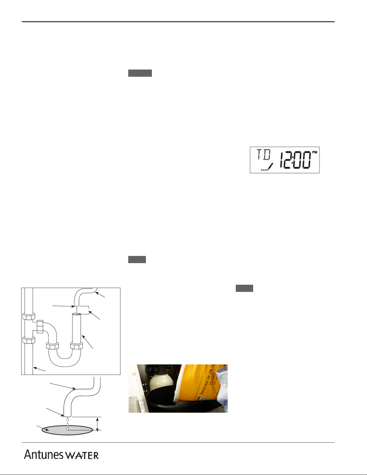
When connecting the drain hose, pay
attention to the following guidelines:
yThe drain line plumbing must
be able support the ow rate
when the system regenerates.
yThe drain line leading out of
the system must be as short as
possible and slope downwards
without any kinks or loops.
yThe drain line plumbing must
be positioned and secured at
least 2 inches above the drain
(Figure 3). This air gap protects
the system from contamination in
the event of a backed-up drain.
yThe drain used must not be
blocked or restricted.
yThe drain used must be as large or
larger than the drain line plumbing.
yThe drain line from the
system should be secured at
the drain using appropriate
mounting hardware.
4. Attach 3/8” OD brine tank tubing
to the control head using the brass
nut and sleeve provided. Do NOT
overtighten the brass nut.
5. Attach the other end of the brine
tank tubing to the brine tank oat
valve using the supplied nut and
sleeves.
OPTION: If desired, connect the brine
tank overow hose from the
overow tting to the oor
drain.
6. Attach Hi-Flo bypass valve to the
control head.
7. Attach the plastic yoke to the
bypass valve.
8. Turn o main water supply.
9. Remove a section of existing pipe
where the softener is going to
be installed. The pipe removed
should be large enough to allow
the ttings needed to connect to
the softener system.
10. Make sure to verify the inlet and
outlet water ow directions on the
softener and the existing plumbing
before making connections.
11. Connect the incoming untreated
water to the valve inlet. Connect
the outlet water connection to the
rest of the home plumbing.
12. Attach inlet and outlet ttings to
the plastic yoke. The yoke has 1”
NPT male threads. Use pipe tape
and/or pipe dope on the threads.
Use a backup wrench when mak-
ing pipe connections. Do NOT
overtighten ttings onto the plastic
yoke.
NOTE: Make sure that local plumbing
codes are followed when mak-
ing connections.
13. Before proceeding, make sure the
bypass valve is in bypass position.
Bypass position is when the valve
handles are across (perpendicular
to) the valve bodies.
14. Turn on the main water supply and
check all new ttings for leaks.
15. Secure the power transformer on
the power cord to the wall or other
location to remove the weight of
the transformer from the cord.
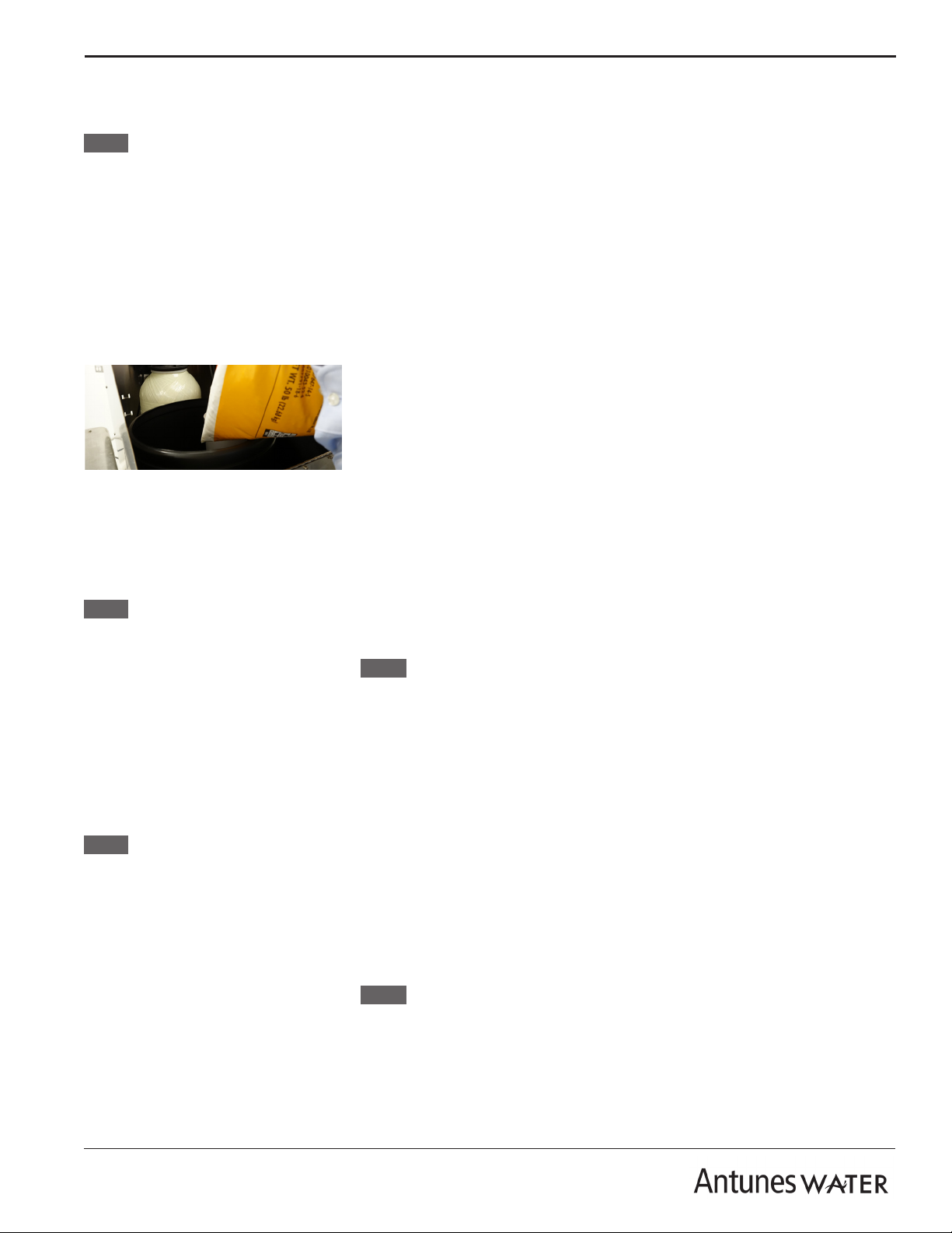
16. Remove the lid of the brine tank
and ll the brine tank with softener
salt (at least 50 lbs.) Replace the
lid when nished.
17. Plug the power cord from the
control head into a grounded GFCI
outlet. Make sure the control panel
is illuminated.
2” (5.1 cm)
minimum
Floor Drain
Secure End
Drain Line
from System
2” (5.1 cm)
minimum
Drain Line
from System
Secure
End
Drain
Standpipe
Figure 2. Drain Line Plumbing
Setting the Clock
Program the controller to set the time of
day.
1. Press and hold either the Up or
Down arrow button on the control-
ler until the programming icon
replaces the service icon and the
parameter display reads TD (Time
of Day).
2. Adjust the displayed time with the
Up and Down buttons.
3. When the correct time is set, press
the Extra Cycle button to lock in
the time and resume normal op-
eration. The unit will also return to
normal operation after 5 seconds if
no buttons are pressed.
Placing the System into
Service
1. After the time of day is set, open
the bypass valve. The open posi-
tion is when the valve handles are
in line with (parallel to) the valve
bodies.
2. Check for leaks at all connections
on the softener control head.
3. Activate a manual regeneration
by pressing and holding the extra
cycle button for 5 seconds. Air and
water will come out of the softener
drain line and water will ll the salt
brine tank.
NOTE: The regeneration will take
approximately an hour to
complete.
4. After the regeneration is complete,
the system is operational.
Operation Check
1. Make sure the water supply to the
softener is on.
2. Proper hardness reduction can be
checked by measuring a sample
of the outlet water for hardness.
3. Collect a water sample from any
tap leading from the softener
system. Run the water for several
minutes to make sure soft water is
at the tap.
4. Measure the hardness using any
test that measures total hardness.

P/N 1011598 Rev. A 11/20 9
RESIDENTIAL WATER SOFTENER
Maintenance
Every Week
Checking Salt Levels
NOTE: Abrasive ‘hard’ water contains
high levels of calcium and
magnesium, causing lime scale
buildup and interfering with
the steamer’s ability to operate
correctly.
1. Remove the lid of the brine tank.
2. Check the level of the salt in the
brine tank. It is recommended that
the brine tank should be lled at
least half-full with salt. The salt
should measure at least 3 inches
above the water level.
3. Break up any salt bridges. Salt
can form a solid layer or “bridge” in
the brine tank. Break up any solid
layers that have formed until the
salt moves freely. This will ensure
that the salt mixes properly with the
water in the brine tank.
NOTE: For stubborn salt layers, warm
water may be added to help
break up solid pieces of salt.
4. Replace the brine tank lid when
nished.
5. Once the salt brine tank has been
lled, a manual regeneration can
be activated if necessary. Press
and hold the extra cycle button
for 5 seconds to start a manual
regeneration.
6. After the regeneration is complete,
the system is operational.
NOTE: The regeneration will take
approximately an hour to
complete.
Every Month
Check Clock Time
The clock should be checked monthly to
make sure the local time is set properly.
1. Look at softener display and check
that displayed time is the same as
local time.
2. If time is incorrect, adjust the time by
following the programming steps in
the Installation section.
Every Six Months
Check Hardness Reduction
The hardness reduction should be
checked every 6 months. Use any test
strips or tester that measures Total
Hardness.
If Total Hardness coming from the
softener system is not less than 1 grain
per gallon (gpg), contact the factory for
more information.
Every Three Years
Cleaning the Salt Brine Tank
1. Unplug the power supply for the
softener.
2. Remove the lid of the brine tank.
3. Disconnect all plumbing connections
to the brine tank and empty the brine
tank. Siphon or dump all water out of
the tank, then dump out the salt and
throw it away.
NOTE: Dissolve blocks or bridges of
salt with hot water if needed.
4. Scrub with soapy water. Mix a
generous amount of dish soap into
one or two gallons (4-8 liters) of
water. Pour it into the tank and scrub
the entire interior with a brush.
5. Rinse the tank. Dump out the soapy
water and rinse with plain water.
6. Replace the brine tank in the
enclosure and reconnect all
plumbing connections to the brine
tank.
7. Fill the brine tank with salt.
8. Once the brine tank has been
lled with salt, activate a manual
regeneration by pressing and holding
the extra cycle button for 5 seconds.
NOTE: The regeneration will take
approximately an hour to
complete.
Every Five Years
Replacing the Softener Resin
Tank
Consult the factory for replacement of the
resin tank.
After a Power Failure
Power Loss
The clock should be checked after a
power loss to the softener system.
1. Look at softener display and check
that displayed time is the same as
local time.
2. If time is incorrect, adjust the time by
following the programming steps in
the Installation section.

P/N 1011598 Rev. A 11/20
10
RESIDENTIAL WATER SOFTENER
Master Programming
Master Programming
Instructions
When the Master Programming Mode is
entered, all available option setting
displays may be viewed and set as
needed.
WARNING: These parameters are
factory set and should not be
changed without consulting
the factory.
Enter Master Programming
Mode
1. Set the Time of Day display to
12:01 PM.
2. Press the Extra Cycle button (to
exit Setting Time of Day mode).
3. Then press and hold the Up and
Down Arrow Buttons together until
the programming icon replaces
the service icon and the Display
Format screen appears.
4. Use the up and down arrows to
change parameter values.
5. Press the Extra Cycle button to
scroll to the next parameter.
6. Press the Extra Cycle button at the
last parameter to save all settings
and return to normal operation.
Figure 3. Softener Controller
Resets
Soft Reset
1. Press and hold the Extra Cycle
and Down buttons for 25 seconds
while in normal Service mode.
2. This resets all parameters to the
system default values [except
the volume remaining in meter
immediate or meter delayed mode
and days since regeneration in the
time clock mode].
Master Reset
1. Hold the Extra Cycle button while
powering up the system. This re-
sets all the parameters in the unit.
2. Check and verify the choices
selected in Master Programming
mode.
NOTE:The control will automatically
disregard any programming
changes and return to normal
operation if it is left in Master
Programming mode for 5 min-
utes without any keypad input.

P/N 1011598 Rev. A 11/20 11
RESIDENTIAL WATER SOFTENER
Abbreviation Parameter
Factory Default
WSS-0948-R WSS-1252-R
Description
DF Display Format GAL GAL Gallons
VT Valve Type DF1b DF1b Standard Down-Flow
Single Backwash
CT Control Type Fd Fd Meter (Flow) Delayed
NT Number of Tanks 1 1 Single Tank System
CUnit Capacity, KGrains 27.8 55.7 Unit Capacity
HWater Hardness, Grains 20 20
(Test water and adjust if
incoming hardness is
higher than 20 grains)
RS Reserve Selection SF SF Percentage Safety Factor
SF Safety Factor % 15 15
Percentage of the system
capacity to be used as a
reserve
DO Day Override 14 14 Not Used
RT Re-Gen Time 2:00 AM 2:00 AM Time of day for
regeneration
BW Backwash (BW) 8 8 Minutes
BD Brine Draw (BD) 72 85 Minutes
RR Rapid Rinse (RR) 8 8 Minutes
BF Brine Rell (BR) 12 24 Minutes
FM Flow Meter Type t0.7 t0.7 3/4” Turbine Meter
Injector # 0 1
Brine Line Flow
Control Rate GPM 0.125 0.25
Drain Line Flow
Control Rate GPM 2 3
NOTE: THE FOLLOWING PARAMETERS ARE FACTORY DEFAULTS AND SHOULD ONLY BE CHANGED BY A QUALIFIED
SERVICE PROFESSIONAL.

P/N 1011598 Rev. A 11/20
12
RESIDENTIAL WATER SOFTENER
Problem Possible Cause Corrective Action
No water comes out of the
lter system.
Inlet/Outlet valves closed. Open the Inlet/Outlet valves.
Regeneration timer is not set. Set regeneration timer.
Water pressure is too low. Check incoming water pressure to ensure that it meets
specications. If not, boost the inlet water pressure.
Controller valve is stuck. Clean controller valve (consult factory).
Low water ow comes out of
the lter system.
See Above. See Above.
The inlet water pressure is too low. Boost the inlet water pressure.
Water isn’t soft.
System regenerating, temporarily bypassed. Wait for regeneration to complete.
No salt in brine tank. Add salt to brine tank.
Salt is bridging in brine tank (not in contact with water). Break up salt bridging.
Salt level is below water level. Add salt to brine tank so salt level is above water level.
Water conditions changed. Set the timer to regenerate more often or consider
installing additional ltration.
Water splashes at drain dur-
ing ush.
Drain line not positioned properly. Reposition the end of the drain line.
Drain not capable of handling ow rate. Clean drain; nd alternate drain.
Water leaks from system t-
ting or connection Fitting broken or loose. Tighten or replace the tting.
Troubleshooting

P/N 1011598 Rev. A 11/20 13
RESIDENTIAL WATER SOFTENER
Item # Part # Description Qty.
17010053 Control Valve, Plastic WSS-0948-R 1
7010054 Control Valve, Plastic WSS-1252-R 1
2 7010046 High Flow Bypass Valve, Plastic 1
3 7010047 Yoke, 1” NPT, Plastic 1
47010042 Drain Line Flow Control WSS-0948-R 1
7010043 Drain Line Flow Control WSS-1252-R 1
5 7010044 Drain Line Retainer 1
6 7010056 Drain Line Elbow Fitting 1
7 7010045 Brine Line Fitting 1
8 7010049 Brine Tank (with valve and lid) 1
9 7010048 Brine Tank Lid 1
10 7010050 Brine Valve 1
11 7010040 Brine Tubing, 3/8” OD 5ft
12
7010051 Pressure Resin Tank w/ Media,
WSS-0948-R 1
7010052 Pressure Resin Tank w/ Media,
WSS-1252-R 1
13 7010041 Drain Line Tubing, 1/2” ID 20ft
Replacement Parts List
(See Exploded Views for more information)
NOTE
Use only genuine Antunes replacement parts in this
unit. Use of parts other than those supplied by the
manufacturer will void the warranty.

P/N 1011598 Rev. A 11/20
14
RESIDENTIAL WATER SOFTENER
Replacement Parts
Exploded View #1
6
1
2
3
4
5
7
9
11
12 8
10

P/N 1011598 Rev. A 11/20 15
RESIDENTIAL WATER SOFTENER
NOTES

Limited Warranty
Equipment manufactured by Antunes has been constructed of the finest materials available and manufactured
to high quality standards. These units are warranted to be free from defects in materials and workmanship for a
period of one year from date of purchase under normal use and service, and when installed in accordance with
manufacturer’s recommendations*.
*To ensure continued proper operation of the units, follow the maintenance procedure outlined in the Owner’s
Manual.
1. This warranty does not cover failures due to improper system installation, defects caused by improper storage or
handling prior to placing of the equipment into service.
2. Antunes reserves the right to make changes in design or add any improvements on any product. The right
is always reserved to modify equipment because of factors beyond our control and government regulations.
Changes to update equipment DO NOT constitute a warranty charge.
3. THIS WARRANTY IS EXCLUSIVE AND IS IN LIEU OF ALL OTHER WARRANTIES, EXPRESSED
OR IMPLIED, INCLUDING ANY IMPLIED WARRANTY OR MERCHANTABILITY OR FITNESS FOR A
PARTICULAR PURPOSE, EACH OF WHICH IS HEREBY EXPRESSLY DISCLAIMED. THE REMEDIES
DESCRIBED ABOVE ARE EXCLUSIVE AND IN NO EVENT SHALL ANTUNES BE LIABLE FOR SPECIAL
CONSEQUENTIAL OR INCIDENTAL DAMAGES FOR THE BREACH OR DELAY IN PERFORMANCE OF
THIS WARRANTY.
4. Prices and specications are subject to change without notice.
www.antuneswater.com
This manual suits for next models
1
Table of contents
Other Antunes Water Dispenser manuals
Popular Water Dispenser manuals by other brands

Fleck
Fleck 5600 Econominder Service manual

Elkay
Elkay LZTL Series Installation, care & use manual

Tapworks
Tapworks NSC9PRO User and installer handbook

Hydrotech Water
Hydrotech Water 565 HIMTLC-100 owner's manual

Judo
Judo JUDOMAT JM 4 WZ-P Installation and operating instructions

Follett
Follett C/E25CR400A/W Installation, operation & service manual

Avalon
Avalon A10-TL Use and care guide

Breville
Breville HotCup VKJ367 manual

Watts
Watts PWSYS-WH-SOFT-PRO-SE - 30K Installation, operation and maintenance manual

Aqua To Go
Aqua To Go Argento Cleaning instructions

Murdock
Murdock A171.8 Series installation instructions

Curtis
Curtis Thermopro Airpot TLXA22 instructions