DiaLog Elite PLC Interface Manual
©
Antx, inc. 2001 Version 1.2 v
Convention Description
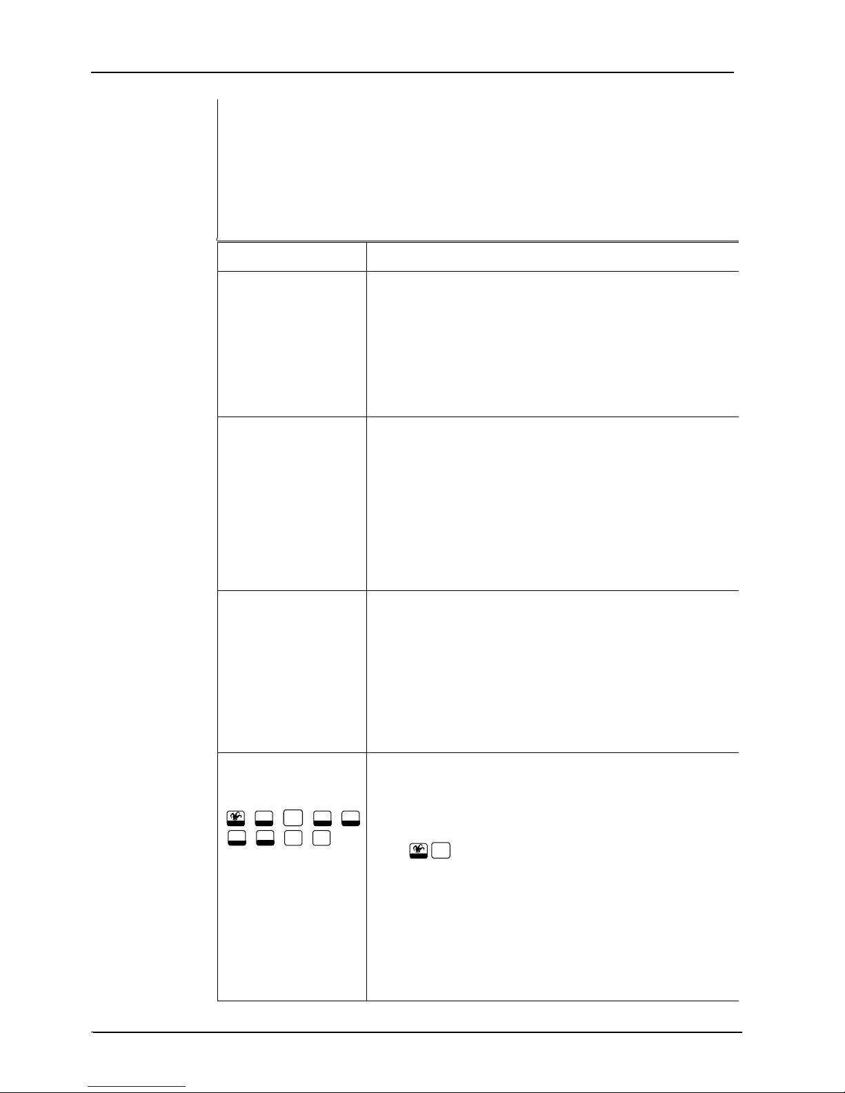
Small rectangular
representation of key
0.1 2 3.4.5.
.6 7.8.9.0.*.
.#.F1.F2.F3.F4.
Indicates keys to press when entering parameter values at the
keypad or when communicating with the DiaLog via a touch-
tone telephone.
EXAMPLE 1:
The person answering the call acknowledges it by pressing the
.* , 8 or 9 key on a Touch-Tone telephone.
EXAMPLE 2:
In Chapter 7, Programming the DiaLog Elite, 0 - 2 in the
What you Enter column means to enter a value between 0 and
2.
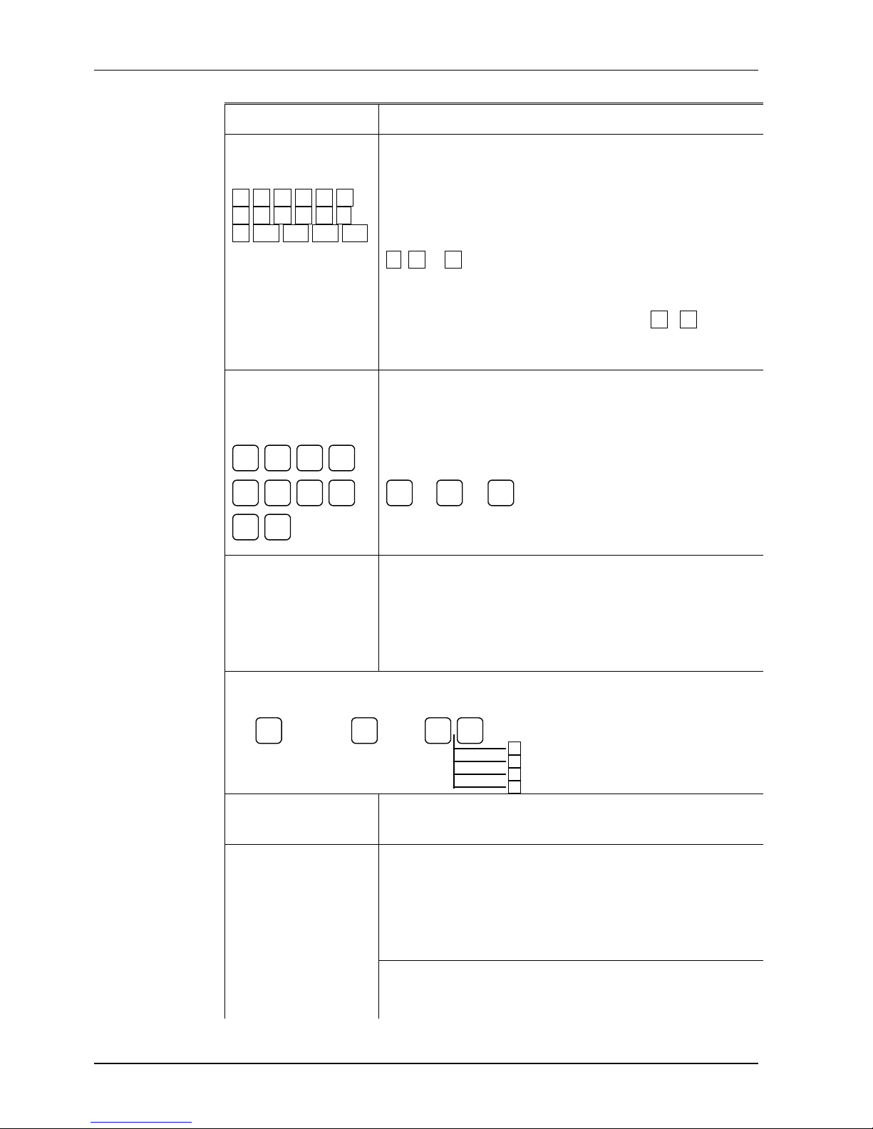
Small rounded
rectangular
representation of a key
These keys are used in Chapter 7, Programming the DiaLog
Elite, to indicate menu selections. These are used in both the
Road Map and the Menu Sequence headings.
0123 EXAMPLE:
4567 9Æ0Æ3
8 9 Means to press the keys 9, 0 and 3 to reach the command.
Road Map ÞThis heading and icon is used at the beginning of a function
description to indicate the complete key sequence that the user
takes to reach the function being described. The Road Map also
includes other parameters within that function.
EXAMPLE:
Channel
Configuration
Relay
Output
Channels
Channel
Number
9Æ3
Æn n
0 Pulse Duration [0-65535]
1 De-energize Relay on Ack.[0-1]
2 Channel Mode [0-1]
3 Channel Alpha ID [A-Z, 0-9]
Description This heading and icon is used to present an overview of the
function being discussed.
Field Summary This heading and icon is used to list all parameters that must be
entered for the function. The heading includes the name of the
Field, Range of values that can be entered, and Factory
Setting.
EXAMPLE:
Field Range Factory Setting
Alarm Delay 0-65535 seconds 3