Antx Messenger 600 User manual

Messenger 600
User’s Guide
Version 1.0.0
May 13, 2020

2

3
Table of Contents
1Description.............................................................................................................................6
1.1 Capabilities.....................................................................................................6
1.2 Monitoring .....................................................................................................6
1.3 Host Server Communications.........................................................................6
2Installation and Setup.............................................................................................................9
2.1 Installation Steps ............................................................................................9
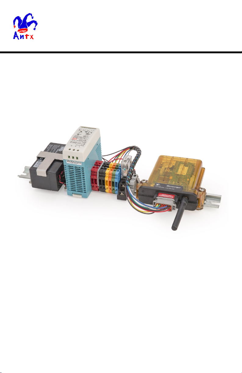
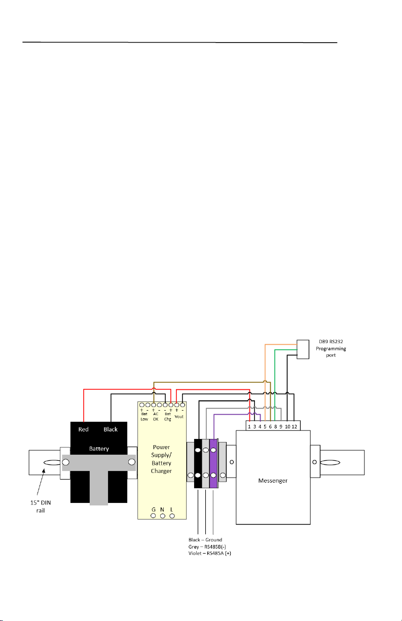
2.2 Mounting the Equipment................................................................................9
2.3 Mounting the Antenna..................................................................................10
3LED States ...........................................................................................................................11
4Channels...............................................................................................................................14
4.1 Defined Channels......................................................................................... 14
4.2 Channel Data................................................................................................ 15
5Modbus ................................................................................................................................15
5.1 RTU Slave....................................................................................................15
5.2 RTU Master.................................................................................................. 15
6Debug Menu.........................................................................................................................16
6.1 Default Configuration and Sample Session.................................................. 17
7Configuration .......................................................................................................................18
7.1 Debug Configuration Commands.................................................................19
7.2 Site Configuration – Type 1.........................................................................22
7.3 Options Configuration – Type 2...................................................................23
7.4 CELL Configuration – Type 3 ..................................................................... 24
7.5 FTP Configuration – Type 4 ........................................................................26
7.6 Serial Port Configuration – Type 6 .............................................................. 27
7.7 Channel Configuration – Type 9..................................................................29
7.8 Report Flag Configuration – Type 12 ..........................................................34
7.9 Date/Time Configuration – Type 16 ............................................................36

4
Table of Figures
Figure 1 - Messenger 600 DINrail Mount .......................................................................9
Copyright and Trademark Information
All Pages Copyright © 2020 Antx RemoteIQ LLC All Rights Reserved.
U.S. Government Users Restricted Rights. Use, duplication, or disclosure by the Government is
subject to restrictions as set forth in applicable laws and regulations. Use of the materials by the
Government constitutes acknowledgment of Antx' proprietary rights in them. This manual may
contain other proprietary notices and copyright information that should be observed.
Information in this document is subject to change without notice. The software described in this
document is furnished under a license agreement or nondisclosure agreement. The software may
be used or copied only in accordance with the terms of those agreements. No part of this
publication may be reproduced, stored in a retrieval system, or transmitted in any form or any
means electronic or mechanical, including photocopying and recording for any purpose other
than the purchaser’s personal use without the written permission of Antx RemoteIQ, LLC.

5
Introduction
This User’s Manual describes installation and setup of the Antx Messenger 600
product.
The Messenger 600 is a cellular, cloud-based monitoring, alarm notification, and
telemetry platform. It supports monitoring and reporting of up to 600 data values from
the industry standard Modbus RTU serial protocol, and support of custom serial
communications to external devices.
Features
The hardware feature set of this platform includes:
•Messenger with LTE modem running on ATT or Verizon networks.
•12VDC battery backup
•120VAC to 12VDC power supply battery charger with main power fail signal
•RS485 port for Modbus RTU communication
•RS232 port for programming using the internal menu system
•Terminal blocks for field connections

6
1Description
1.1 Capabilities
The Messenger is a highly configurable platform for remote monitoring and control
applications. Some of the capabilities are listed below.
•virtual real-time transfer of monitored conditions
•local computations from monitored conditions
•time stamping of monitored data and events
•battery backed historical data/event buffers
•automatic monitoring of max/min for analog values
•event and data logging
•telemetry of monitored conditions to host server based applications via cellular
•OTA programming and diagnostics
1.2 Monitoring
All monitored values can be transmitted via cellular to the RemoteIQ cloud-based
server. Monitored values are transmitted based on time or events. Notification events
are based on rules set by the user and each event can generate an immediate report.
Telemetry includes cellular connectivity and GPS for asset location.
The Messenger 600 reads values using the Modbus RTU protocol over an RS485 serial
connection. The user programs each of the 600 values that are to be read into
Messenger channels, which are numbered from 301 to 900.
1.3 Host Server Communications
The Messenger utilizes a proprietary protocol to send notifications and to receive OTA
commands from the RemoteIQ server. Each notification sent typically consists of
location, date/time, an event code, and associated data. An event code provides a
unique identifier to indicate the reason that notification is being sent – e.g. normal
scheduled update or an engine diagnostic message received. A description of the
protocol, format of messages, and definition of event codes is available on request
(reference protocol document “M09-PRTCLxxx”).
Some of the conditions on which notifications can be sent to the host server are listed
below:
•Any monitored value exceeding a pre-defined or user-defined limit
•Any diagnostic message received from the engine bus
•A digital input changing state (on/off)
•A digital output changing state

7
•An analog input exceeding a user-defined delta for a user-defined period of
time
•A scheduled update
•System faults
•Power on or reset
1.3.1 Alarm Notification
The RemoteIQ backend provides notification to designated personnel via:
•Text message
•Email
•Voice
Each method allows the user to acknowledge the message received.
1.3.2 Event Codes
Every message sent by the Messenger 600 to a host-based server application is
triggered by an event. The event generates a message and the message contains an
Event Code. The Event Code uniquely identifies to the server the reason the message is
being sent. Some of the messages generated contain data, others serve as just
notification that a particular event has occurred. Protocol document “M09-PRTCLxxx”
contains a list of all event codes.
1.3.3 Positive Acknowledgement
The Messenger 600 is configured to require a message acknowledgement from the host
server providing complete end-to-end verified communication. Message
acknowledgement provides a verifiable mechanism that a message was delivered, even
during poor network conditions.
1.3.4 Store and Forward Data Queue
There are several scenarios where a message may not be deliverable – network down,
host server down, poor connectivity to name a few. In the event that a message cannot
be delivered, it is stored in memory and is continually re-sent until properly
acknowledged. This store and forward memory is non-volatile and remains intact
during power off.
1.3.5 Real-Time Clock (RTC)
The RTC is used to time stamp data records and events. All messages sent to the host
server contain a time stamp to provide a chronology of data/events to the end user. The
RTC is battery backed to provide time keeping during power off. If the RTC is
configured to be automatically set, the Messenger will set time after every power on

8
and perform a time check every midnight. If the RTC time differs from actual time by
more than 30 seconds, the RTC is adjusted.
The RTC can be set in one of the following ways:
Method
Description
Automatic
via Cell
This is the default setting. The
Messenger will set the RTC from an
internet NIST time server.
Automatic
via GPS
The Messenger will set the RTC
from the date/time read from the GPS
module.
Manually
Set the time via the Debug port
through the Maintenance menu.
OTA/SMS
The RTC is set from an OTA config
command or an SMS config
command.
Configuration parameters in OPTIONS and CELL are used to define how the RTC is
set.
1.3.6 Packaging
The Messenger 600 comes mounted on a DINrail for easy mounting in panels or is
available in a NEMA 4X enclosure.

9
2Installation and Setup
This section provides information on installing the Messenger and confirming its initial
operation.
It is recommended to read this entire chapter before starting installation.
2.1 Installation Steps
Installation consists of the following steps:
1. Unpack the Equipment.
2. Mount the Equipment.
The Messenger should be mounted in a vertical position to try and minimize
the chance of water entering through the antenna connections. The antenna
wires should have a service loop just below the antenna connectors.
3. Connect Main Power.
2.2 Mounting the Equipment
The Messenger 600 is shipped mounted to a DINrail as shown below.
Figure 1 - Messenger 600 DINrail Mount

10
2.3 Mounting the Antenna
In general, the antenna should be mounted with an unobstructed view of the sky. The
GPS side works best when it can see the horizon. If the antenna is mounted outside and
may be subject to lightning, a surge arrestor can be inserted between the Messenger and
the antenna. If the antenna is mounted inside, it should be located near a window.
NOTE: Service loops should be provided for the antenna cabling, near the antenna
connections to minimize water ingress through the RF coax connections.

11
3LED States
There are 8 LEDs visible to the user to indicate various system conditions (LED
locations). Specific information is conveyed to the user via LED blink patterns.
Blinking of LEDs can be disabled via a configuration setting (OPTIONS
Configuration). On power-up, an LED test is performed by blinking all LEDs every
second for 3 seconds. Following the LED test, the LEDs blink based on the following
conditions:
•LED 1 (GRN) - System
State
Rate
Definition
Blink
1 blink every 5 seconds
Sleep Mode
Blink
1 blink every second
CPU Run - Normal
Blink 5 blinks every second Boot Loader Mode
(all other LEDs off)
On or Off
Solid
System Failure
•LED 2 (RED) - Cell Registration
State
Rate
Definition
Blink
Rapid blink, then off
Ok - Rx/Tx Activity w/CELL Modem
Blink 1 blink every second Not Registered
Check APN
Verify valid cellular account
Off
Solid
Ok - Registered
•LED 3 (RED) - Cell Status
State
Rate
Definition
Blink
10 every second
No SIM card or communications
failure with modem
On
Solid
Not Ready/Fault
Blink
1 blink every second
Error
Off
Solid
Ok

12
•LED 4 (RED) - CAN
State
Rate
Definition
On
Solid
Fault, no engine bus activity
detected
Blink
2 blinks every second
OBD traffic detected, but no
response to data queries
Blink
1 blink every second
Engine bus not selected, check DIP
Switch 2
Off
Solid
No Faults, engine bus activity
detected
•LED 5 (RED) - GPS
State
Rate
Definition
Blink
1 blink every second
No Fix
Off
Solid
Fix
•LED 6 (RED) - Modbus
State
Rate
Definition
Blink
Rapid (burst)
Ok - Rx/Tx Activity on Port 2 or 3
On
Solid
Fault (comm. timeout error)
Off
Solid
Ok - No Faults
•LED 7 (RED) - USR1
State
Rate
Definition
Blink
1 blink every second
Lithium Coin Cell battery is low or
RTC has stopped
On
Solid
If DIN1, DIN2, DIN3, or DIN4 are
configured as pulse counter inputs,
this LED will light when any input is
activated, off when all inputs idle
Off
Solid
No Faults

13
•LED 8 (RED) – CELL Signal Strength
(Enabled from OPTIONS Setup – default is Enabled)
Rate
Definition
OFF
Not registered or not detectable
1 blink, 1.2 sec pause
signal strength <6, weak
2 blinks, 1.2 sec pause
signal strength <=12
3 blinks, 1.2 sec pause
signal strength <=18
4 blinks, 1.2 sec pause
signal strength <=24
5 blinks, 1.2 sec pause
signal strength >24, strong

14
4Channels
The Messenger maps all monitored conditions into channels. Each channel has data
storage and configuration parameters. Data storage holds current value, max/min
values, and other run time data values. Configuration consists of user settable
parameters that define rules on how the data values are to be processed (Channel
Configuration).
Every channel in the Messenger is referenced by a fixed channel number, e.g. RPM is
always channel 52. There is a set of pre-defined channels (numbers 1-300) and a set of
Modbus channels (numbers 301-900). The Modbus channels are user configurable for
reading/writing digital or analog values from a Modbus RTU slave device.
4.1 Defined Channels
The following channels are pre-defined in the Messenger:
Table 1: Pre-Defined Channels
Channel
Number
Channel
Name
Type
Description
Start Digital Channels (data values are ‘0’ or ‘1’)
1
Cell
Digital
(System)
Status of cellular modem operation
•1=fault
•0=normal
2
Comm
Digital
(System)
Status of any serial port used for
communications with external device
(MODBUS Master, Slave, or proprietary)
•1=fault
•0=normal
4
User DIN1
Digital
•0 – On AC power
•1 – On Battery power
Start MODBUS Channels
301-900
Modbus
User
Defined
Analog or Digital channels read from
Modbus RTU Slaves

15
4.2 Channel Data
All values read from a Modbus slave device are continually updated and tested as
defined by the configuration parameters. For each channel, based on its type (analog or
digital), there is a basic set of data collected. For purposes of discussion, the term “not
normal” is used to indicate an analog value that has violated a limit threshold or a
digital value that does not match its configured ‘normal’ state.
NOTE: The RemoteIQ configuration should be made to match the configuration in the
Messenger hardware. Alarm notification is only configured in the RemoteIQ system.
5Modbus
The Messenger can be configured as a Modbus Master, Modbus Slave or both. This is
done by setting the Mode of one of the available serial ports, 2 or 3. Port 2 supports
RS232 and RS485, Port 3 only supports RS232.
5.1 RTU Slave
Being configured as a Modbus RTU Slave device allows SCADA/HMI software to read
channel values from the Messenger. Setting up a serial port is the only configuration
necessary to enable Modbus Slave operation.
The Modbus register map for all channel data values is available on request. Reference
document number “Messenger MODBUS Slave xxxxx”.
5.2 RTU Master
When configured as a Modbus RTU Master device, the Messenger reads register values
from Modbus Slave devices.
In addition to setting up a Modbus Master serial port, channels in the Messenger must
be configured to receive the register values read from the slave device. In Channel
Configuration, define the Modbus Slave address, the register data type to read, the
register number, how to interpret or scale the data being read, and any alarm limits.

16
6Debug Menu
The debug menu is a text based menu system accessible via terminal emulation
software running on a PC (i.e. TeraTerm or Hyperterminal) or via a PC based utility
that connects to the Messenger OTA via TCP. Debug menus allow the user to view or
change configuration parameters, view data values and history logs, see
communications between CPU and attached peripherals, and to clear accumulated data
values or logs.
The Debug Menu can be accessed via a direct serial RS232 connection. The default
port settings are: 9600 baud, 8 databits, 1 stop bit, no parity
NOTE: Once connected, press the ‘Enter’ key to see the Main Menu (example below).
________MessengerAB________
Site Name: Site Name
Model : CP750/ANTX LVW3 MBUS J1939
Version : AB v8.1.8D 02/26/20
Date/Time: 05/13/20 14:34:09
Asset ID : 357766090587705
GPRS Reg : Home
Server : Primary
MSISDN : 15772170946
Local IP : 10.208.242.239
Network : LTE
CELL RSSI: 16 (18,15)
GPS : No Fix
DataQue : 9
PushQue : 0
Output 1 : Off
Output 2 : Off
Output 5 : Off
1) View Config
2) Timers
3) Data
4) Events
5) Reports
6) Setup
7) Maint
8) J1939 Diags
Cmd =>
Most menu navigation commands are single alpha-numeric entries, no carriage return
(Enter) required. However, when modifying configuration parameters, the
configuration string entered must be followed by a carriage return (Enter).

17
6.1 Default Configuration and Sample Session
The Default configuration for the Messenger 600 is supplied as a separate file named:
MessengerAB-600 Default Config.txt
A sample annotated programming session is supplied as a separate file named:
MessengerAB-600 Sample Debug Session.doc

18
7Configuration
The Messenger is a highly configurable platform with several methods in place to allow
a user to read and/or modify the whole configuration or any part of. All configuration
parameters are stored in non-volatile memory.
Configuration parameters can be changed using the following methods:
•User modify via debug menu, using direct RS232 serial connection
•Transfer configuration file, using “X-modem 1k” over direct RS232
•Transfer configuration file via FTP, initiated via debug menu
All configuration parameters are read/written using text strings with commas to
separate values in the string. This basic format is the same for all methods listed above.
Some of the methods put a “wrapper” around the configuration line to aid in transport
and decoding on the receive end.
The basic configuration line format (referenced as CL) is described below:
CL= x,<i,>y,zzzz,y,zzzz,y,zzzz,…,y,zzzz
Where:
•the commas are required as the delimiter between value fields
•
x
is a unique number identifying the configuration line type (e.g. Site=1,
Serial=6, Channel=9, etc)
•
<i,>
is an optional index used with specific configuration line types that have
more than 1 element (e.g. there is more than 1 Serial Port and more than 1
Channel)
•
y
is a parameter code identifying the configuration parameter that follows
•
zzzz
is the configuration parameter (this parameter could be an integer, a
floating point number, or a text string as defined by the parameter code
y
)

19
This table identifies the available configuration line types and their type code.
Table 2: Configuration Line Types
Configuration Line Types
Type
Code
Reference
Description
Optional Index
1
Site
Messenger global settings
None
2
Options
System Options settings
None
3
Cellular
Cellular communication settings
None
4
FTP
FTP settings
None
6
Ports
Serial port parameters
Serial Port Number
Range 1-4
9
Channels
Set scaling and alarm parameters
for channels
Channel Number
Range 301-900
12
Report Flags
Defines data types to include in
reports to the host server
Channel Number
Range 301-900
16
Date/Time
Set the Date/Time externally
None
7.1 Debug Configuration Commands
Users can manage the current configuration via the built in Debug Menu system. From
the main menu, select Site Setup (6). From Site Setup, select User Input (1). From the
User Input prompt, the following read/modify commands are applicable.
7.1.1 Read Command
This is the read configuration command format:
255,x<,i><CR>
Where:
•
255
is the read command
•
x
is the configuration line type code
•
<,i>
is an optional index that is a function of the line type code
•
<CR>
is a line terminating carriage return
Some examples using the READ command:
Examples:
255,1<CR>
Prints Site config
255,6,2<CR>
Prints Serial Port 2 config
255,6,255<CR>
Prints all Serial Port configs
255,255<CR>
Prints a Full System config
By issuing the “255,255” command, the user can capture a complete system
configuration to a file. This file can then be used as the master configuration file. This

20
master config file can then be modified and loaded back into the system or any segment
that needs to be reconfigured.
7.1.2 Reset Command
To reset a configuration to factory defaults, use the following command format:
256,x<,i><CR>
Where:
•
256
is the reset command
•
x
is the configuration line type code
•
<,i>
is an optional index that is a function of the line type code
•
<CR>
is a line terminating carriage return
Some examples using the RESET command:
Examples:
256,1<CR>
Reset Site config
256,6,2<CR>
Reset Serial Port 2 config
256,256<CR>
Reset System config
CAUTION USING THIS COMMAND:
This may reset the serial port in use.
Communications with the unit could be
lost.
7.1.3 Global Command
The global command can be used to set the same parameter to the same value, within
the same configuration type, for multiple indexes. The global command only works
with Geo-Fence, Channel, Schedule, Report Flags, and J1939 configuration types.
The global command format is:
257,x,i-j,y,zzzz<CR>
Where:
•
257
is the global command
•
x
is the configuration line type code
•
i
is a required starting index
•
j
is a required ending index, greater than
i
(NOTE: the range of indexes from
i
to
j
is inclusive and by definition are sequential)
•
y
is a parameter code identifying the configuration parameter that follows
•
zzzz
is the configuration parameter (this parameter could be an integer, a
floating point number, or a text string as defined by the parameter code
y
)
Table of contents
Other Antx Industrial Equipment manuals