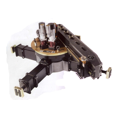
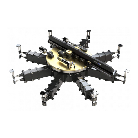
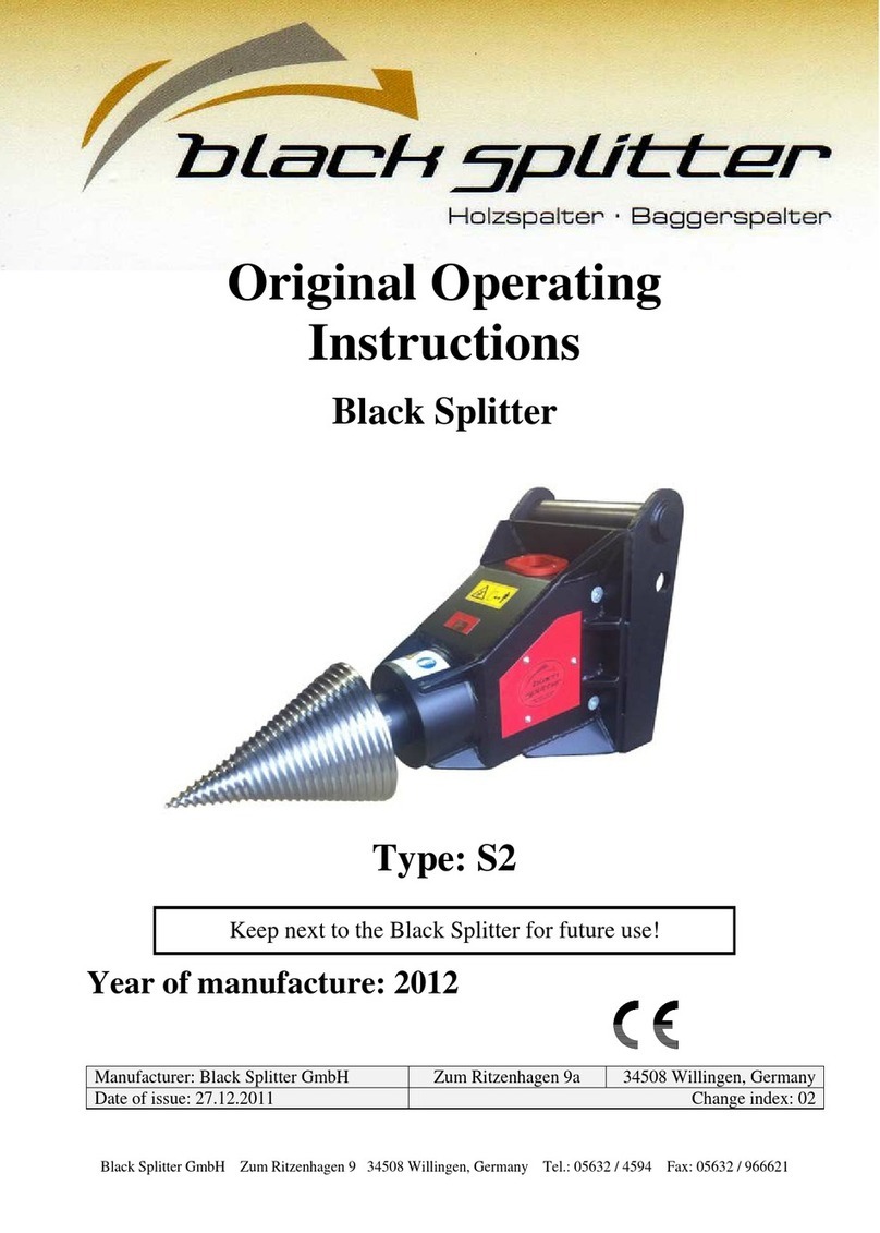
Team SILK SX012 User manual

INSTRUCTION MANUAL
SX012 & AXL012 FLANGE FACING
AND GROOVING MACHINE
Revision E
TEAM®
Shap Road
Kendal
Cumbria
LA9 6RU
United Kingdom
Tel: +44 (0) 1539 729009
Fax: +44 (0) 1539 729359
TEAM® is an ISO9001 registered company
© Copyright 2022 TEAM®

SX012/AXL012 Flange Facing and Grooving Machine
1
THIS INSTRUCTION MANUAL
This Instruction Manual describes how to safely install, operate and maintain the
SX012/AXL012 Flange Facing and Grooving Machine. It is an essential part of the
equipment and it is important that you take the time to read it thoroughly.
Additional copies are available for purchase from TEAM® or from an authorised agent.
HEALTH AND SAFETY AT WORK
This document should be read carefully and fully understood before proceeding to install,
use, maintain or service the equipment.
DO NOT USE THE EQUIPMENT UNTIL YOU ARE SURE YOU KNOW HOW IT WORKS
AND WHAT ITS INTENDED FUNCTION IS.
The equipment described in this document is intended to be used by professional personnel
in an industrial environment.
Installation, operation, maintenance and servicing should only be carried out by suitably
qualified and experienced personnel.
The following symbols are used to highlight important areas of this document which relate to
potential hazards and residual risks:
Important statements regarding the use, handling or operation
of the equipment.
Warnings to prevent injury to operator and or local personnel.
Cautions to prevent misuse and damage to the equipment.
IMPORTANT NOTICE
TEAM® has made every effort to ensure that the information given in this document is as
accurate and as up-to-date as possible at the time of publication.
TEAM® will not be held responsible for any accident or equipment failure that may occur due
to misuse, unauthorised modification, inadequate maintenance, use of non genuine parts or
use by unsuitable personnel.
TEAM® reserves the right to update, correct or otherwise change any information relating to
this equipment, at any time and without obligation.
TEAM® also reserves the right not to provide updated, corrected or amended versions of this
publication.

SX012/AXL012 Flange Facing and Grooving Machine
2
The specification and design of the SX012/AXL012 Flange Facing and Grooving Machine
(including the copyright, design right or other intellectual property in them) shall, at all times,
remain the property of TEAM®. Where any designs or specifications have been supplied by
the client for manufacture by TEAM® or to the order of the client then the client warrants that
the use of those designs or specifications for the manufacture, processing, assembly or
supply of the SX012/AXL012 Flange Facing and Grooving Machine shall not infringe the
rights of any third party.
WARRANTY, SPARES AND AFTER SALES SERVICE
Subject to the provisions of any bespoke terms and conditions of sale, this SX012/AXL012
Flange Facing and Grooving Machine is guaranteed for twelve (12) months from the date of
purchase against faulty materials and/or workmanship. During this period it will be repaired
or have parts replaced free of charge provided that:
1 it is returned immediately to TEAM® with evidence of the purchase date;
2 it has been purchased by the user and has not been used for hire purposes;
3 it has not been misused or handled carelessly and has been stored and maintained in
accordance with any instructions provided by TEAM®;
4 repairs have not been attempted other than by a member of TEAM® service team or by a
service provider duly authorised by TEAM® to carry out such repairs; and
5 the cost of such repair or replacement does not exceed the original purchase value.
A full spare parts service is available from TEAM® or from an authorised agent. Additionally,
TEAM® can supply a recommended spare parts kit suitable for a specified period of normal
service life.
Also offered is a Factory Service, in which the equipment can be returned to TEAM® for
inspection. A quotation may then be given for the overhaul, repair or replacement of the
equipment.
TEAM® warrants that the SX012/AXL012 Flange Facing and Grooving Machine supplied will
at the time of delivery correspond to the description given by TEAM®. All other warranties,
conditions or terms relating to fitness for purpose, quality or condition of the SX012/AXL012
Flange Facing and Grooving Machine, whether express or implied by statute or common law
or otherwise are excluded to the fullest extent permitted by law.

SX012/AXL012 Flange Facing and Grooving Machine
3
CONTENTS
SECTION 1 TECHNICAL DESCRIPTION .......................................................................... 7
1.1 Introduction ...................................................................................................... 7
1.2 Equipment description ..................................................................................... 7
1.2.1 Drive ring and bearing assembly........................................................... 7
1.2.2 Saddle ................................................................................................... 8
1.2.3 Gearbox ................................................................................................. 9
1.2.4 Motor unit .............................................................................................. 9
1.2.5 Optional accessories ............................................................................. 9
SECTION 2 SPECIFICATIONS ........................................................................................10
SECTION 3 SAFETY INFORMATION ..............................................................................13
3.1 Warnings and cautions ..................................................................................13
SECTION 4 CONTROLS AND BASIC OPERATION .......................................................16
4.1 Location and function of the controls.............................................................16
4.1.1 Machine controls .................................................................................16
4.1.2 Filter/lubricator pack controls ..............................................................18
4.2 Basic operation of the equipment ..................................................................19
4.3 Lifting and slinging arrangements .................................................................19
SECTION 5 SITE OPERATION ........................................................................................20
5.1 Warnings and cautions ..................................................................................20
5.2Setting up the equipment ..............................................................................21
5.2.1 Unpacking the machine .......................................................................21
5.2.2 Drive Ring and Bearing Assembly Installation ....................................22
5.2.3 Saddle Assembly Installation ..............................................................25
5.2.4 Setting up the tool - facing and grooving ............................................26
5.2.5 Selecting the traverse .........................................................................27
5.3 Using the equipment......................................................................................28
5.3.1 Connection to Air Supply .....................................................................28
5.3.2 Starting the machine - Facing and Grooving ......................................29
5.4 Removing the equipment ..............................................................................30
5.5 Storing the equipment ...................................................................................30
SECTION 6 FAULT DIAGNOSIS......................................................................................31
6.1 Introduction ....................................................................................................31
6.2 Fault diagnosis chart .....................................................................................31
SECTION 7 MAINTENANCE INSTRUCTIONS ................................................................33
7.1 Introduction ....................................................................................................33
7.2 Periodic maintenance ....................................................................................33
7.3 Recommended lubricants ..............................................................................34
7.4 Removal and refit procedures .......................................................................35
7.4.1 Drive motor ..........................................................................................35
7.4.2 Gearbox ...............................................................................................36
7.4.3 Shear pin replacement ........................................................................36
SECTION 8 PARTS LISTS ...............................................................................................37
8.1 Main assembly ...............................................................................................39
8.1.1 AXL012 Machine .................................................................................39

SX012/AXL012 Flange Facing and Grooving Machine
4
8.1.2 SX012 Machine ...................................................................................39
8.2 Base clamping assembly ...............................................................................41
8.3 AXL012 Drive ring and bearing assembly .....................................................43
8.4 SX012 Drive ring and bearing assembly .......................................................46
8.5 Saddle ...........................................................................................................49
8.6 Toolpost - standard........................................................................................52
APPENDIX A Cutting tools as applied to portable machines ........................................53
APPENDIX B Surface metrology .......................................................................................56
APPENDIX C V-Groove measurement ..............................................................................59
APPENDIX D Air motor manufacturers information .......................................................61
APPENDIX E DECLARATION OF CONFORMITY .............................................................67

SX012/AXL012 Flange Facing and Grooving Machine
5
Fig. 1 AXL012 Flange Facing and Grooving Machine (above)
SX012 Flange Facing and Grooving Machine (below)

SX012/AXL012 Flange Facing and Grooving Machine
6
`
Fig. 2 AXL012 Flange Facing and Grooving Machine – exploded view
SX012 not shown as only additional feature is a second motor unit/gearbox

SX012/AXL012 Flange Facing and Grooving Machine
7
SECTION 1 TECHNICAL DESCRIPTION
1.1 INTRODUCTION
The TEAM® SX012/AXL012 Flange Facing and Grooving Machine is constructed from the
highest quality materials and great care has been taken in its design and manufacture. Its
design will give every satisfaction provided that it is properly installed, operated and
maintained in accordance with the information contained within this manual.
Take care of this manual; it is an essential source of information.
1.2 EQUIPMENT DESCRIPTION
The purpose of the TEAM® SX012/AXL012 flange facing and grooving machine is designed
to machine full faced, raised face and grooved flanges up to 300 mm (11.750") in diameter,
at any location having a minimum pneumatic air supply 1.6 m3/m, 6 bar (60 cfm,87 psi).
The machine can achieve a variety of surface finishes from 6.3 µm Ra to 1.6 µm Ra when
turning and 1.6 µm Ra to 0.8 µm Ra when polishing. The machine can also produce a
'gramophone' finish, 'O' ring grooves and 'V' grooves, and alternatively lens ring facings.
The machine consists of four main assemblies (see Fig.1):
a. Drive ring and bearing assembly
b. Saddle
c. Gearbox
d. Motor unit
The machine is available as either a single motor AXL012 or a twin motor SX012 version.
The function and operation of these variants are identical.
1.2.1 Drive ring and bearing assembly
The drive and bearing assembly forms the main body of the machine which
comprises two main sub-assemblies: the drive assembly and the spur ring gear.
The drive assembly
The drive assembly, which is the fixed part of the machine, has four base clamp
blocks bolted to the base plate on the underside, and two flanges for mounting the
drive gearboxes.
The drive assembly houses an idler gear, which transfers the drive from the
gearbox to the spur ring gear. A cross-roller bearing assembly is clamped between
the drive assembly and the base plate, and the inner (rotating) race is clamped to
the spur ring.

SX012/AXL012 Flange Facing and Grooving Machine
8
A fixed gear ring is attached to the drive cover and is used in conjunction with the
saddle pick-up gear, which revolves as the saddle rotates, to give the saddle its
feed source.
Spur ring gear
The spur ring gear assembly, which is the rotating part of the machine, is clamped
to the cross-roller bearing assembly by a clamp plate and the ring gear provides
the clamping location for the saddle assembly. An idler gear in the drive assembly
drives the spur ring gear.
1.2.2 Saddle
The saddle is mounted on the drive ring located within the drive ring assembly and
provides a rigid structure to which the toolpost is fixed.
Drive input to the toolpost feed gearbox is derived from the drive ring pick-up gear
that rotates around the fixed internal gear located in the drive ring assembly in a
planetary motion.
Toolpost traverse in and out is provided by a leadscrew which is driven by the
saddle gear train. Traverse is selected by the traverse selector.
The saddle can achieve cuts to a maximum depth of 1 mm (0.040 in) without
flanged holes and 0.5 mm (0.020 in) with flanged holes.
Alternative toolposts can be fitted to the saddle depending on the machine
application. For cutting tools and surface finish refer to Appendices A and B at the
end of this manual.
Fig. 3 Saddle

SX012/AXL012 Flange Facing and Grooving Machine
9
TRAVERSE
SELECTOR LEVER
POSITION
FEED (mm per
revolution)
FEED (in per revolution)
COARSE (IN)
0.81 mm
0.032 in.
FINE (OUT)
0.20 mm
0.008 in.
Table 1 Feed rates
1.2.3 Gearbox
The gearbox is mounted on the drive assembly cover and transmits the drive from
the air motor through two bevel gears and an intermediate idler gear to the bearing
drive gear (spur ring gear).
1.2.4 Motor unit
The machine is driven by a 0.8 kW (1.07 hp) pneumatic motor with a free running
output speed of 382 rpm and incorporating an exhaust manifold and muffler.
The motor is attached to a motor flange with a bevel gear and bearing keyed and
secured to the motor spindle. The motor and flange assembly is attached to the
gearbox.
The AXL012 machine version is fitted with one motor and the SX012 version is
fitted with two motors.
1.2.5 Optional accessories
The following optional accessories are available upon request:
'V' groove machining kit
'V' groove measuring kit
Lens ring machining and polishing kit

SX012/AXL012 Flange Facing and Grooving Machine
10
SECTION 2 SPECIFICATIONS
Fig. 4a AXL012 Single drive principle dimensions
Fig. 4b SX012 Twin drive principle dimensions
PRINCIPAL DIMENSIONS:

SX012/AXL012 Flange Facing and Grooving Machine
11
+Overall machine height (including 12.7mm, ½”
spacers)
245 mm
9.65"
Maximum base width (with motor filter and claw
attached)
Single drive – AXL012
609.6 mm
24”
Twin drive – SX012
762 mm
30”
TRANSPORTATION DIMENSIONS:
Single Drive – AXL012
Net weight (machine only)
42 kg
92 lbs
Gross weight (including accessories)
82 kg
180 lbs
Length
810 mm
31.9"
Height
460 mm
18.1"
Width
750 mm
29.5"
Twin Drive – SX012
Net weight (machine only)
60 kg
132 lbs
Gross weight (including accessories)
100 kg
244 lbs
Length
810 mm
31.9"
Height
460 mm
18.1"
Width
750 mm
29.5"
OPERATIONAL DIMENSIONS:
Facing range:
Minimum diameter
zero
zero
Maximum diameter with standard tooling
292 mm
11.5"
Maximum diameter with cranked tooling
300 mm
11.75"
Toolpost travel:
Maximum toolpost vertical travel
70 mm
2.75"
Base gripping range:
Minimum recommended outside diameter
112 mm
4.0"
Maximum recommended outside diameter
330 mm
13.0"
Gearbox feed rate and machine speed:
Position 1 Coarse 'in'
0.81 mm/rev
0.032"/rev

SX012/AXL012 Flange Facing and Grooving Machine
12
Position 2 Fine 'out'
0.20 mm/rev
0.008"/rev
Saddle free running speed
37 rpm +/- 10%
Saddle speed at max motor torque
24 rpm
NOISE EMISSION:
Single Drive – AXL012
Emission sound pressure level
92 dB(A)
Instantaneous sound pressure value. Indicate either
less than 63 Pa (130 dB) or actual value if above.
<130dB
Emission sound power level. Indicate either less than 80
dB (A) or actual value if above.
101 dB(A)
Single Drive – AXL012
Type: MODEC
Maximum power output at 177 rpm
MT10RT0177DCL4F
0.8 kW 1.07 hp
Twin Drive – SX012
Maximum power output at 177 rpm
1.6 kW
2.14 hp
Maximum speed free running
382 rpm
Minimum recommended air supply
1.6m3/min
60 cfm
6 bar
87 psi
Air inlet thread
3/4" BSP

SX012/AXL012 Flange Facing and Grooving Machine
13
SECTION 3 SAFETY INFORMATION
3.1 WARNINGS AND CAUTIONS
GENERAL:
ALL SAFETY PROCEDURES MUST BE OBSERVED AND STRICTLY
ADHERED TO WHEN INSTALLING, USING, MAINTAINING AND
SERVICING THIS EQUIPMENT.
ONLY TRAINED AND COMPETENT PERSONNEL SHOULD INSTALL,
USE, MAINTAIN AND SERVICE THIS EQUIPMENT.
ENSURE AN EMERGENCY STOP IS ALWAYS WITHIN REACH OF THE
OPERATOR.
INTENDED USE OF THIS EQUIPMENT:
THIS EQUIPMENT IS FOR USE BY PROFESSIONAL, TRAINED
PERSONNEL WORKING IN AN INDUSTRIAL ENVIRONMENT.
THIS EQUIPMENT IS INTENDED FOR USE ON METALS AND
ANALOGOUS SUBSTANCES.
THIS EQUIPMENT IS NOT INTENDED FOR USE ON WOOD, PLASTIC OR
SIMILAR ANALOGOUS SUBSTANCES.
USE OUTDOORS:
THIS EQUIPMENT SHOULD NOT BE USED DURING SEVERE WEATHER
CONDITIONS.
PERSONNEL SHOULD NOT OPERATE THIS EQUIPMENT IN WEATHER
CONDITIONS WHICH MAY GIVE RISE TO THE FOLLOWING:
- INADEQUATE VISIBILITY
- THE BUILD-UP OF ICE, SNOW, WATER, SAND OR DUST ON
PLATFORMS, LADDERS, CONTROLS, VISUAL INDICATORS,
MOVING PARTS, ETC.
- RISK OF INJURY DUE TO STRONG OR GUSTING WINDS
THIS EQUIPMENT SHOULD BE SUITABLY PROTECTED FROM ALL
SEVERE WEATHER CONDITIONS.

SX012/AXL012 Flange Facing and Grooving Machine
14
PERSONAL PROTECTIVE EQUIPMENT:
THE USE OF PERSONAL PROTECTIVE EQUIPMENT IS
RECOMMENDED WHEN WORKING WITH THIS EQUIPMENT.
SUGGESTIONS INCLUDE SAFETY HAT, GAUNTLET GLOVES, SAFETY
GOGGLES, SAFETY SHOES, AND FLAME RETARDANT COVERALLS.
BREATHING APPARATUS MAY BE NECESSARY WHEN A TOXIC
ATMOSPHERE EXISTS.
OTHER PROTECTIVE EQUIPMENT MAY BE REQUIRED AS PER THE
PLANT OPERATOR’S REQUIREMENTS.
PERSONNEL WORKING ABOVE GROUND LEVEL MUST ALSO WEAR A
SAFETY HARNESS CONNECTED TO A SUITABLE ANCHOR POINT OR
FALL ARRESTOR.
LIFTING:
ENSURE LIFTING IS CARRIED OUT IN A SAFE AND PROPER MANNER,
IN ACCORDANCE WITH APPLICABLE HEALTH AND SAFETY
REGULATIONS.
ALWAYS KNOW THE WEIGHT OF THE EQUIPMENT AND THE
COMPONENT PARTS. REFER TO THE SPECIFICATION PAGE IN THIS
MANUAL OR THE MARKING PLATE ON THE EQUIPMENT.
THE USE OF MECHANICAL LIFTING DEVICES MAY BE A MANDATORY
REQUIREMENT FOR LIFTING THIS EQUIPMENT.
INSTALLATION AND REMOVAL:
THIS EQUIPMENT IS INTENDED TO BE PORTABLE AND MAY BE USED
IN A VARIETY OF LOCATIONS AND ORIENTATIONS. ALWAYS ENSURE
THAT THIS EQUIPMENT IS PROPERLY SUPPORTED AND RESTRAINED
DURING THE INSTALLATION AND REMOVAL PROCESS.

SX012/AXL012 Flange Facing and Grooving Machine
15
PNEUMATICS:
ENSURE THE CORRECT HOSES, VALVES AND FITTINGS ARE USED.
DO NOT PRESSURISE THIS EQUIPMENT IF ANY OF THE HOSES,
VALVES OR FITTINGS ARE LEAKING OR DAMAGED.
DO NOT PRESSURISE THIS EQUIPMENT UNTIL YOU ARE SURE THE
EQUIPMENT HAS BEEN CORRECTLY INSTALLED AND THE CONTROL
VALVES ARE CLOSED.
DO NOT USE AIR MOTORS WITH DEFECTIVE SILENCERS. THIS MAY
CAUSE UNNECESSARY NOISE AND IMPAIR THE PERFORMANCE OF
THE EQUIPMENT.
NEVER PLACE ANY BODY PARTS ADJACENT TO AN AIR EXHAUST.
COMPRESSED AIR FORCED INTO THE SKIN IS DANGEROUS AND MAY
RESULT IN A SERIOUS SKIN DISORDER.
ENSURE THE PNEUMATIC SYSTEM IS ISOLATED AND DE-
PRESSURISED BEFORE MAKING ANY ADJUSTMENTS TO THIS
EQUIPMENT.
ENSURE THE PNEUMATIC SYSTEM IS ISOLATED AND DE-
PRESSURISED BEFORE DISCONNECTING ANY HOSES.
DO NOT ALLOW THE LUBRICATOR TO SUPPLY EXCESSIVE AMOUNTS
OF OIL TO THE PNEUMATIC SYSTEM. DEPENDING ON MOTOR SIZE 5
TO 8 DROPS PER MINUTE AT FULL MOTOR SPEED IS
RECOMMENDED.
NEVER LEAVE THE PNEUMATIC SYSTEM PRESSURISED WHILE
UNATTENDED.

SX012/AXL012 Flange Facing and Grooving Machine
16
SECTION 4 CONTROLS AND BASIC OPERATION
4.1 LOCATION AND FUNCTION OF THE CONTROLS
The following controls are incorporated into the machine:
4.1.1 Machine controls
Fig. 5 Machine controls
Traverse selector lever
Selects the rate at which the toolpost traverses the work piece per machine
revolution. The central position ‘N’ disengages the traverse feed.
TRAVERSE
SELECTOR LEVER
POSTION
FEED (mm per
revolution)
FEED (in per
revolution)
COARSE (IN)
0.81 mm
0.032 in.
FINE (OUT)
0.20 mm
0.008 in.

SX012/AXL012 Flange Facing and Grooving Machine
17
Auto feed selector
The auto feed selector determines whether the machine rotation is engaged or not.
AUTO FEED
SELECTOR POSTION
MACHINE ROTATION
PULLED OUT
Engaged
PUSHED IN
Disengaged
Toolpost movement hand wheel
The toolpost movement hand wheel determines the vertical position of the tool and
the corresponding depth of cut. Turn the hand wheel anti-clockwise to move the
tool towards the work piece.
TOOLPOST
HANDWHEEL
TOOL DIRECTION
TURN CLOCKWISE
Away from work piece
TURN ANTICLOCKWISE
Towards work piece

SX012/AXL012 Flange Facing and Grooving Machine
18
4.1.2 Filter/lubricator pack controls
A gate valve on the pack is used to set the machine speed at the desired RPM
when the control valve is fully open. To set the speed proceed follow the
instructions in section 5.3.1.
For the air motor type fitted to the machine, the filter/lubricator oil regulator control
is adjusted to provide a recommended lubrication rate of 5 drops per minute at full
motor speed.
Fig. 6 Filter/lubricator pack controls

SX012/AXL012 Flange Facing and Grooving Machine
19
4.2 BASIC OPERATION OF THE EQUIPMENT
The basic operation of the machine follows the routine:
1. Lifting the machine from its packing case.
2. Checking the machine for completeness and condition.
3. Removal of the saddle and toolpost assembles from the drive ring assembly
4. Lifting and positioning the drive ring on the flange to be machined.
5. Securing the machine with the fast mounting plates.
6. Centralising the machine and check whether parallel with the flange.
7. Fitting the saddle and toolpost assembly to the drive ring.
8. Setting the tool for facing and grooving.
9. Performing the machining operation.
10. Removal of the machine on completion and preservation and packing.
4.3 LIFTING AND SLINGING ARRANGEMENTS
The AXL012 machine when complete and in its packing box weighs 82 kg.
The SX012 machine when complete and in its packing box weighs 100 kg.
DO NOT ATTEMPT TO MANUALLY MOVE THE MACHINE IN ITS PACKING BOX.
ALWAYS USE A MECHANICAL LIFTING DEVICE.
Four lifting eyebolts are provided on the drive ring to enable lifting the assembled machine
out of its packing box.
The AXL012 assembled machine weighs 42 kg.
The SX012 assembled machine weighs 60 kg
DO NOT ATTEMPT TO MANUALLY LIFT THE MACHINE OUT OF THE PACKING CASE.
ALWAYS USE A MECHANICAL LIFTING DEVICE.
THIS DRIVE UNIT SHOULD BE LIFTED USING SUITABLE MECHANICAL EQUIPMENT.
WHEN SETTING UP THE MACHINE ON A VERTICAL FLANGE THE LIFTING CHAIN
SHOULD BE LEFT IN PLACE UNTIL THE MACHINE IS FULLY SECURED.
This manual suits for next models
1
Table of contents
Other Team Industrial Equipment manuals
Popular Industrial Equipment manuals by other brands
ABB
ABB XAC26064 Operation manual

Comco
Comco MicroBlaster MB1005 Operation and service instructions
Mayr
Mayr EAS 437 Series Installation and operation instructions
TriangleTube
TriangleTube PRESTIGE Excellence Series manual

HEIDENHAIN
HEIDENHAIN M12 Mounting instructions
ITW Dynatec
ITW Dynatec DYNAMINI 4-HOSE Technical documentation
