Belanger CUBE Installation manual

Cube® Installation & Startup Manual
1MANUAL963 Rev03
Cube®Installation and Startup


Belanger® Equipment Owner’s Manual
Cube® Installation & Startup Manual
Copyright 2022
Belanger, Inc®
This manual and the accompanying equipment are protected by United States trademark, copyright, and patent laws. You
may make one copy of this manual. Do not make additional copies of this manual or electronically transmit it in any form
whatsoever, in whole or in part, without the prior written permission of Belanger, Inc.®
The registered trademarks used in this document are the property of their respective owners. The use of such trademarks is
for reference purposes only and does not imply sponsorship or approval of Belanger, Inc.®by these companies or any
companies affiliated with their respective owners.


Current Revision Log
1MANUL963 Belanger, Inc. * PO BOX 5470. * Northville, MI 48167-5470 * Ph (248) 349-7010 * Fax (248) 380-9681
Rev
Release
Date
Page
Description
02
09/22/21
5-1
Added an Important Note about the installation of the radiant heating system (per Project
#10151)
03
04/26/22
7-4
Added to Step 10: and the four (4) bearing bolts (per Project #10151)
7-5
Inserted step between Step 13 & 14: Tighten the four (4) bearing bolts on the side wheel
hub assembly. (per Project #10151)


Cube®Installation & Startup
1MANUL963 Belanger, Inc. * PO BOX 5470. * Northville, MI 48167-5470 * Ph (248) 349-7010 * Fax (248) 380-9681 iii
Table of Contents
Chapter 1 Introduction.................................................................................................1-1
Belanger Incorporated Limited Warranty .....................................................................................1-1
Operational Warning ....................................................................................................................1-2
Important Safety Information........................................................................................................1-3
Safety Symbols and Signal Words...............................................................................................1-3
IMPORTANT Safety Information –MUST READ ........................................................................1-4
UL Information..............................................................................................................................1-6
Scope of This Manual ..................................................................................................................1-7
Torque Values..............................................................................................................................1-8
Component Identification .............................................................................................................1-9
Chapter 2 Recommended Installation Sequence Checklist.......................................2-1
Main Checklist..............................................................................................................................2-1
Chapter 3 Trades..........................................................................................................3-1
Required Man Hours....................................................................................................................3-1
Scope of Work..............................................................................................................................3-1
Electrical Coordination Meeting ...................................................................................................3-1
Plumbing Coordination Meeting...................................................................................................3-2
Penetrating the Wall for Cube® Utilities.......................................................................................3-2
Chapter 4 Electrical Overview and Panels..................................................................4-1
General.........................................................................................................................................4-1
Electrical Standards Overview.....................................................................................................4-1
Best Practice Methods .................................................................................................................4-3
Cube® Carriage Electrical Cables ...............................................................................................4-5
Cube® Carriage Panel.................................................................................................................4-6
Cube® Building Panel..................................................................................................................4-7
Cube® HMI Panel........................................................................................................................4-8
Cube® Local Network ..................................................................................................................4-9
Cube Static IP Address: ........................................................................................................................4-9
Chapter 5 Getting Started ............................................................................................5-1
Installation Overview....................................................................................................................5-1
Skilled Trades...............................................................................................................................5-9
Equipment Locations....................................................................................................................5-9
Establishing an Origin in the Bay.................................................................................................5-9
Fastening Needs and Other Required Materials........................................................................5-10
Cube® Utility Supplies Recommendations................................................................................5-11
Chapter 6 Frame and Carriage Assembly...................................................................6-1
Frame Overview...........................................................................................................................6-1
Frame Assembly: Rails and Head Beams ...................................................................................6-1
Frame Assembly: Attaching Leg Assemblies.............................................................................6-13
Frame Assembly: Position Frame in Bay...................................................................................6-16
Establish Lines in Bay to Position the Frame Assembly......................................................................6-16
Place & Secure the Frame Assembly in Position.................................................................................6-19
Carriage Prep.............................................................................................................................6-21
Location of Equipment Room ..............................................................................................................6-21
Attach the CAT Track Support Assembly to the Frame.......................................................................6-21
Disengage the Roller Drive..................................................................................................................6-24
Carriage Placement on Frame Assembly: Overview.................................................................6-26
Carriage Placement on Frame Assembly: Preferred Method....................................................6-27
Carriage Placement on Frame Assembly: Alternate Method.....................................................6-32
Attach Safety Stops and Proximity Target to Entrance Rails.....................................................6-38
Attach the Utility Manifold to the Frame.....................................................................................6-39
Connect the Carriage Utility Lines to the Utility Manifold...........................................................6-40

Cube®Installation & Startup
ii Belanger, Inc. * PO BOX 5470. * Northville, MI 48167-5470 * Ph (248) 349-7010 * Fax (248) 380-9681 1MANUL963
Table of Contents
Chapter 6 Frame and Carriage Assembly (cont.) .....................................................6-47
Carriage Movement....................................................................................................................6-47
Re-Engage the Roller Drive ................................................................................................................6-47
Chapter 7 Side Wheel Hub Assemblies.......................................................................7-1
Attach Side Wheel Hub Assemblies to Carriage..........................................................................7-1
Chapter 8 Smart Spray Assemblies.............................................................................8-1
Mount the Smart Spray Assemblies onto the Carriage................................................................8-1
Connect Feed Manifolds to Smart Spray Manifolds.....................................................................8-4
Connect Airlines to Smart Spray Cylinders................................................................................8-10
Connect LED Cable to Smart Spray LED ..................................................................................8-11
Chapter 9 Photo-Eyes...................................................................................................9-1
Photo-Eye: Standard....................................................................................................................9-1
Photo-Eye: Available Add-on Options..........................................................................................9-1
Photo-Eye: Layout and Description Overview..............................................................................9-1
Photo-Eye: General Setup ...........................................................................................................9-3
Photo-Eye: Wiring ........................................................................................................................9-4
Photo-Eye: Undercarriage Wash & Short Bay Considerations....................................................9-5
Load Position Photo-Eyes............................................................................................................9-6
Chapter 10 Undercarriage Option..............................................................................10-1
Undercarriage Overview.............................................................................................................10-1
Undercarriage In-Ground Placement .........................................................................................10-2
Undercarriage In-Ground Connections ......................................................................................10-4
Chapter 11 Air Panels.................................................................................................11-1
Air Panels: Overview..................................................................................................................11-1
Main System Regulator Panel....................................................................................................11-2
Triple Foam Air Panel.................................................................................................................11-3
Single Foam Air Panel................................................................................................................11-4
Chapter 12 Injection Chemical System (ICS)............................................................12-1
ICS Assembly: Overview............................................................................................................12-1
ICS Assembly Installation...........................................................................................................12-1
Connect Chemical Lines from Utility Manifold to ICS ................................................................12-3
Select Metering Tips & Connect Suction Tubing to ICS Injectors..............................................12-5
ICS Assembly: Electrical Connections.......................................................................................12-8
Chapter 13 High-Pressure Pump Assembly..............................................................13-1
Overview.....................................................................................................................................13-1
Installation of High-Pressure Pump Assembly...........................................................................13-2
High-Pressure Pump Assembly Hose Connections...................................................................13-5
High-Pressure Pump Assembly Electrical Connections ............................................................13-8
Chapter 14 MixStir® for Chemical Tire Application..................................................14-1
Overview.....................................................................................................................................14-1
Mounting the MixStir® Assembly ...............................................................................................14-2
MixStir® Assembly Utility Connections ......................................................................................14-4
Chapter 15 Water Softener Option.............................................................................15-1
Water Softener ...........................................................................................................................15-1
Getting Started ...........................................................................................................................15-2
Water Softener Installation CP 213............................................................................................15-3
Model 213S OD / WA and WB Connections..............................................................................15-6
Component Functionality (Scanned)........................................................................................15-10
Water Softener Conversion Charts ..........................................................................................15-12

Cube®Installation & Startup
1MANUL963 Belanger, Inc. * PO BOX 5470. * Northville, MI 48167-5470 * Ph (248) 349-7010 * Fax (248) 380-9681 iii
Table of Contents
Chapter 16 Spot Free Rinse (RO) Option..................................................................16-1
Specifications.............................................................................................................................16-1
Safety Warnings.........................................................................................................................16-5
Utility Requirements and Dimensions........................................................................................16-6
Installation..................................................................................................................................16-7
Storage Tank Connections.........................................................................................................16-8
Plumbing and Electrical Connections ........................................................................................16-9
Install Pur-Clean Auto Back Wash Head .................................................................................16-11
Pump Water Hose Connection to Utility Manifold....................................................................16-12
RO Installation Final Check List...............................................................................................16-12
Chapter 17 Signage Options......................................................................................17-1
Wait/Go Sign..............................................................................................................................17-1
Navigational Sign .......................................................................................................................17-1
Combination Sign.......................................................................................................................17-2
Floor Mount................................................................................................................................17-2
Signage for Position Loading Photo-Eyes .................................................................................17-3
Chapter 18 Pneumatic Connections..........................................................................18-1
Main Air to Pneumatic Manifold Assembly.................................................................................18-1
Side Wheel Head Cylinder Circuit Overview..............................................................................18-1
Side Wheel Rail Assembly Cylinder Circuit Overview ...............................................................18-2
Smart Spray Pivot Cylinder Circuit Overview.............................................................................18-3
Smart Spray CTA Foam Generator Circuit Overview................................................................18-3
OverGlow™Pneumatic & Chemical Solution Overview............................................................18-5
Foam Rain Pneumatic & Chemical Solution Overview..............................................................18-6
Triple Foam Pneumatic Circuit Overview...................................................................................18-7
Triple Foam Chemical Solution Overview..................................................................................18-8
Single Foam Pneumatic & Chemical Solution Overview ...........................................................18-9
Chapter 19 Initial Startup Procedure of Cube®........................................................19-1
1) Initial Inspection and Power Up .............................................................................................19-1
2) Inspect and Adjust Axis Drives ..............................................................................................19-1
3) Load ShineMitt® Cleaning Material onto Hubs......................................................................19-3
4) Inspect and Adjust Pneumatics ...........................................................................................19-13
5) Inspect and Adjust the Carriage Assembly..........................................................................19-16
6) Inspect and Adjust Chemical and Water Delivery Systems.................................................19-27
7) Review All Bay and Equipment Room I/O ...........................................................................19-49
8) Configure Applications & Wash Packages to Match Menu Sign and Business Plan ..........19-49
9) Run Test Vehicles................................................................................................................19-49


Chapter 1 - Introduction
Chapter 1
Introduction


Cube®Installation & Startup
1MANUL963 Belanger, Inc. * PO BOX 5470. * Northville, MI 48167-5470 * Ph (248) 349-7010 * Fax (248) 380-9681 1-1
Chapter 1 Introduction
Belanger Incorporated Limited Warranty
LIMITED WARRANTY:
Equipment:
Subject to the limitations stated below, Seller warrants that the Equipment sold hereunder, which is fabricated by Seller,
shall be free from defects in workmanship and material under normal use and service for a period of 1 year plus 30
days from the date of invoice - CATPumps will be warranted for 2 years from the date of invoice.
Parts:
Subject to the limitations stated below, Seller warrants that the Parts sold hereunder, shall be free from defects in
workmanship and material under normal use and service for a period of 90 days from the date of invoice.
Limitations on All Warranties:
The warranties contained in this Section 13 are subject to the following limitations: (1) they are void if the factory
specifications for operation and maintenance, found in original equipment manuals, and component manuals, are not
followed, or if other than factory authorized erection, alterations or modifications are made to any Parts or Equipment;
(2) defective Parts are warranted to the Purchaser only for repair or replacement through an authorized Purchaser or
Distributor of Seller, or direct with Seller for a period of 13 months from the date of invoice; however, this warranty
excludes all claims for failure resulting from normal wear and tear, improper installation, omission of factory specified
preventative maintenance, misuse, abuse, negligence, third party damages, or acts of God and Purchaser agrees to
submit to and assist Seller or its authorized Purchaser or Distributor in conducting in-warranty inspections of the Goods
including inspection of any Equipment or Parts claimed to be defective by the Purchaser; (3) the cost of providing labor
or repair to replace Equipment and Parts warranted to Purchaser will be included within the warranty only if such claim
is made within 120 days from the date of invoice and then only during normal business hours through an authorized
Purchaser or Distributor of Seller, or direct with Seller, and labor and service provided beyond the labor warranty
period shall be subject to labor charges at the rates established by the local authorized Purchaser or Distributor or
direct with Seller; (4) the warranties shall be void for all Equipment failures and premature Part wear caused by the
use of corrosive chemicals in the wash process, and the following list includes some, but not all, of the particularly
corrosive chemicals that if used in conjunction with Equipment or Parts will void the warranty: Hydrofluoric Acid,
Ammonium Bi-fluoride, Bromic Acid, Muriatic Acid, Sulfonic Acid, Phosphoric Acid, Hydrogen Cyanide, Hydrochloric
Acid, Sodium Hydroxide and Chlorinated Solvents; (5) Seller makes no warranty, express or implied, with respect to
the design or operation of any entire system, in which Seller’s Equipment or Parts sold hereunder are mere
components;(6) in no event shall Seller be liable for any incidental, special, consequential, punitive or exemplary
damages resulting from the furnishing, performance or use of any Goods or services sold pursuant hereto, whether
due to a breach of contract, breach of warranty, negligence or any other claim at law or equity. Seller shall not be
liable for any damages of any kind, including, but not limited to, loss of business; inconvenience, or property damage
of any kind; nor for any damages of whatever nature resulting in any way from the Purchaser’s selection and use of
any chemicals not manufactured exclusively by Seller but used with the purchased Equipment or Parts; or for any
service not expressly provided herein related to or arising from the Equipment or Parts sold. Seller shall not be liable
for damages resulting from Purchaser’s use of any engineering recommendations, sales representations, technical
assistance, advice or data other than that information contained in Belanger manuals; (7) all warranties, express,
implied, or statutory, pertaining to the Equipment and Parts apply to the Purchaser only; are not transferable; are fully
set forth herein; and no addition to or modification thereto shall be binding upon the Seller, unless made in writing and
signed by a duly authorized employee of Seller.
No Other Warranties:
THIS LIMITED WARRANTY FOR EQUIPMENT AND PARTS IS EXPRESSLY IN LIEU OF ALL OTHER
WARRANTIES, EXPRESS OR IMPLIED, WHETHER STATUTORY OR OTHERWISE, INCLUDING ANY
IMPLIED WARRANTY OF MERCHANTABILITY OR WARRANTY OF FITNESS FOR A PARTICULAR
PURPOSE. THE IMPLIED WARRANTIES OF MERCHANTABILITY AND FITNESS FOR PARTICULAR
PURPOSE CONTAINED IN THE UNIFORM COMMERCIAL CODE –SALES ARE EXPRESSLY
DISCLAIMED.
Copyright ©2020 by Belanger, Inc. All rights reserved. No part of this work may be reproduced or transmitted in any
form or by any means, electronic or mechanical, including photocopying and recording, or by any information storage
or retrieval system, except as may be expressly permitted by the 1976 Copyright Act. Belanger reserves the right to
change or modify the Belanger Inc. Limited warranty without notice.

Cube®Installation & Startup
1-2 Belanger, Inc. * PO BOX 5470. * Northville, MI 48167-5470 * Ph (248) 349-7010 * Fax (248) 380-9681 1MANUL963
Chapter 1 Introduction
Operational Warning
Formulations containing the chemicals listed below are particularly dangerous and should not
be used even at low concentrations:
•Hydrofluoric Acid
•Ammonium Bi-fluoride
•Bromic Acid
•Muriatic Acid
•Sulfonic Acid
•Phosphoric Acid
•Hydrogen Cyanide
•Hydrochloric Acid
•Chlorinated Solvents
Belanger, Inc., does not endorse or condone the use of chemicals that are potentially dangerous
to human health, the environment or property. Belanger recognizes that it is the right and sole
decision of the end user operators of our equipment as to the type and dilution ratio of the
chemicals used in their facilities. We strongly recommend that the end user does not select
products containing any of the chemicals listed above as an ingredient in the wash solutions.
The chemicals listed above are potentially dangerous to human health, and have a detrimental,
deteriorating effect on the equipment and the facility. Be advised that a portion of, or all of your
warranty will be voided if you determine to use any of the chemicals listed above as an ingredient
in the wash solutions in conjunction with your Belanger automatic car wash equipment:
Limitation (4), of Paragraph (8), Limited Warranty, of the Belanger Terms and Conditions of
Sales describes the potential limitation of warranty due to your chemical selection:
(4) This warranty shall be void for all equipment failures and premature component wear
caused by the use of corrosive chemicals in the wash process. The following list includes
some, but not all, of the particularly corrosive chemicals that if used in conjunction with
Belanger equipment will void the warranty: Hydrofluoric Acid, Ammonium Bi-fluoride, Bromic
Acid, Muriatic Acid, Sulfonic Acid, Phosphoric Acid, Hydrogen Cyanide, Hydrochloric Acid,
and Chlorinated Solvents. The Purchaser also agrees to accept the responsibility and liability
for the selection and use of any chemicals listed above.
However, should the end user decide to use formulations containing any of the above
ingredients, the end user should institute a comprehensive training program and implement
detailed operational parameters within their organization for the proper handling and treatment
of such products to minimize the potential dangers involved. Consult your chemical supplier for
assistance in establishing operational guidelines in the use of their products. MSDS (Material
Safety Data Sheet) should be obtained from the chemical supplier before using any chemical
formulation.
CAUTION
During the installation process the installer is responsible for re-tightening
ALL lugs, set screws and terminals located in the electrical panels.
Components may vibrate loose during shipping.
Cube®Installation & Startup
1MANUL963 Belanger, Inc. * PO BOX 5470. * Northville, MI 48167-5470 * Ph (248) 349-7010 * Fax (248) 380-9681 1-3
Chapter 1 Introduction
Important Safety Information
This section introduces the hazard and safety precautions associated with installing, maintaining, or
servicing this product. Before performing any task on this product, read this safety information and
the applicable sections in this manual, where additional hazards and safety precautions for your task
may be found. Electrical shock could occur and cause death or serious injury if these safe service
procedures are not followed.
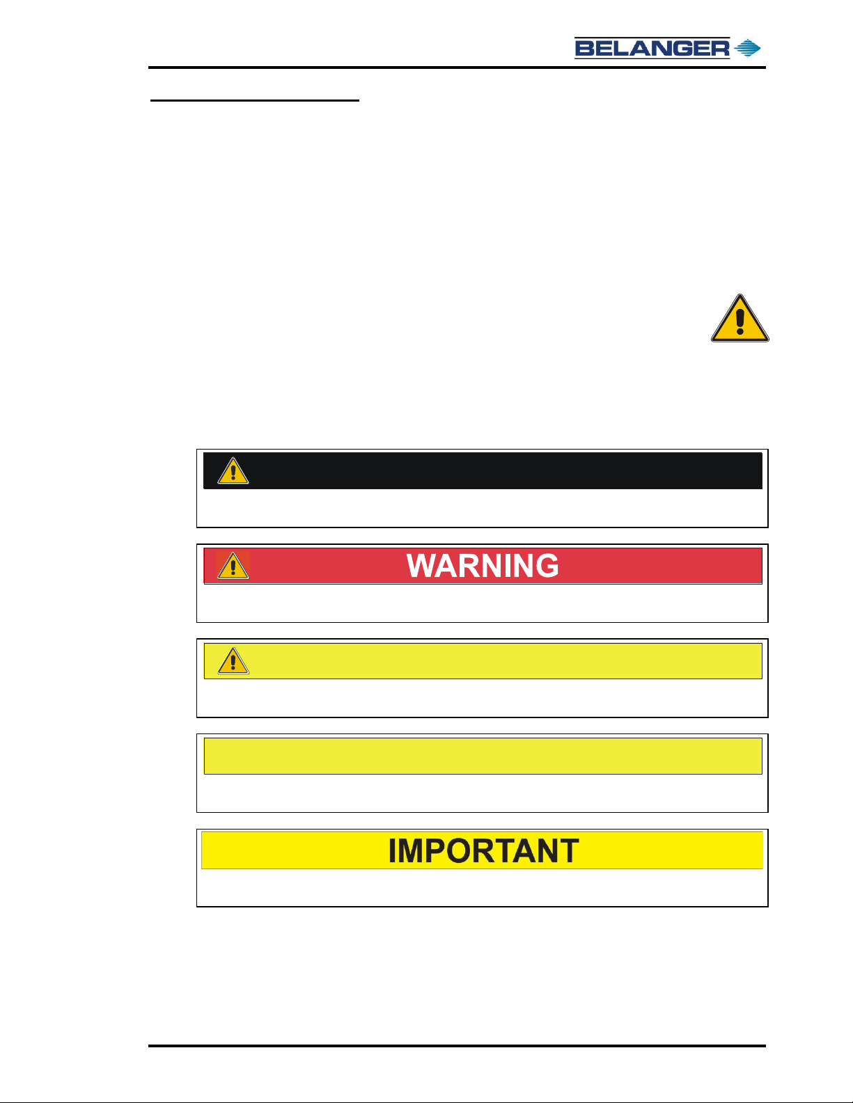
Safety Symbols and Signal Words
Alert Symbol
This safety alert symbol is used in this manual and on warning labels to alert you to
precautions, which must be followed to prevent potential personal safety hazards.
Obey safety directives that follow this symbol to avoid possible injury or death.
Signal Words
The signal words used in this manual and on warning labels tell you the seriousness of particular
safety hazards. The precautions that follow must be followed to prevent death, injury, or damage
to the equipment.
DANGER
This signal word is used to alert you to a hazard or unsafe practice which WILL RESULT IN
DEATH OR SERIOUS INJURY
This alerts you to a hazard or unsafe practice which COULD RESULT IN DEATH OR
SERIOUS INJURY
CAUTION
This signal word designates a hazard or unsafe practice which MAY RESULT IN MINOR
INJURY
CAUTION
When used by itself, CAUTION designates a hazard or unsafe practice, which MAY RESULT
IN PROPERTY OR EQUIPMENT DAMAGE
When used by itself, IMPORTANT designates information that should be followed exactly as
written.
Read the Manual
Read, understand, and follow this manual and any other labels or related materials supplied with
this equipment. If you do not understand the procedure, call a Belanger, Inc®. representative at
248-349-7010. It is imperative to your safety and the safety of others to understand the
procedures before beginning work.
Cube®Installation & Startup
1-4 Belanger, Inc. * PO BOX 5470. * Northville, MI 48167-5470 * Ph (248) 349-7010 * Fax (248) 380-9681 1MANUL963
Chapter 1 Introduction
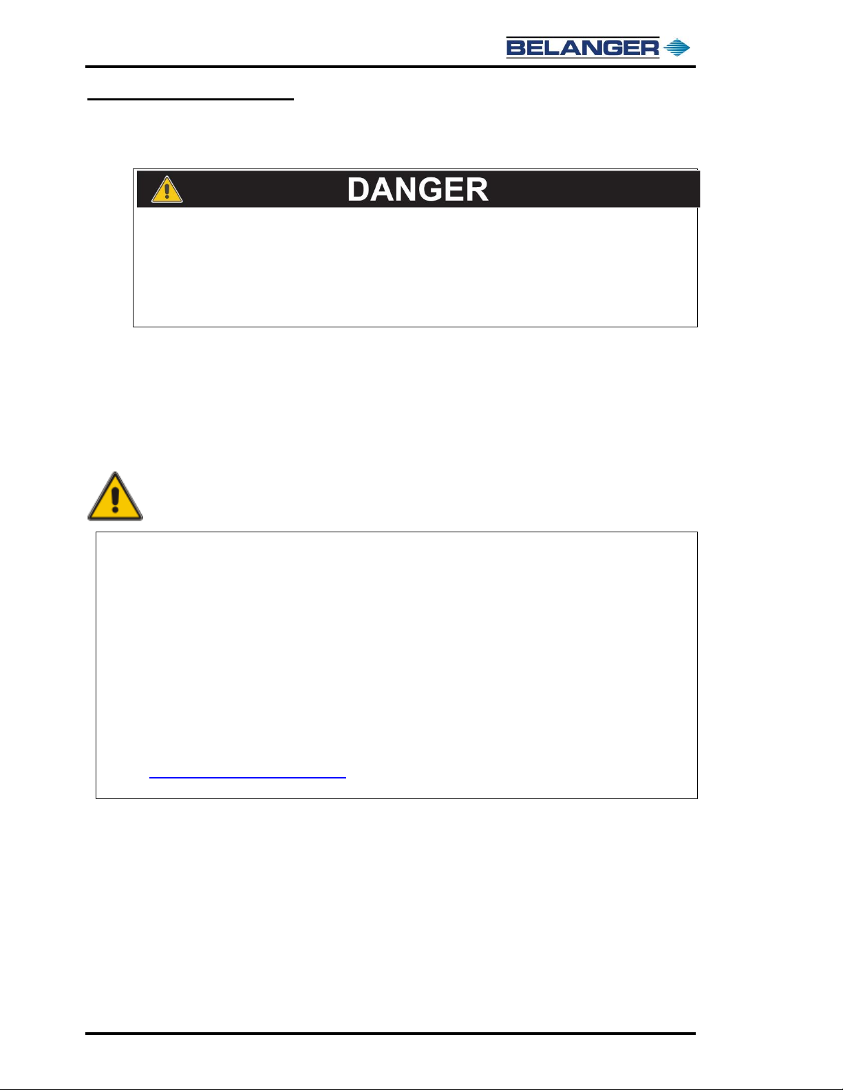
IMPORTANT Safety Information –MUST READ
Safety Warnings
DISCONNECT THE MAIN POWER SUPPLY AND
DISSIPATE ALL POTENTIALLY HAZARDOUS
ENERGY SOURCES PRIOR TO SERVICING OR
MAINTAINING EQUIPMENT
Belanger® recommends that all workers observe the OSHA (U.S. Department of
Labor Occupational Safety & Health Administration) Lockout / Tagout procedure
to dissipate all potentially hazardous energy sources (i.e. - electrical, mechanical,
hydraulic, pneumatic, chemical, thermal, etc.) prior to performing service or
maintenance on machinery and equipment.
Note: Reference the OSHA standard for the Control of Hazardous Energy (Lockout/Tagout), Title 29
Code of Federal Regulations (CFR) Part 1910.147 and the example provided in 1910.147
Appendix A for practices and procedures necessary to disable machinery or equipment, thereby
preventing the release of hazardous energy while employees perform servicing and maintenance
activities. The standard outlines measures for controlling hazardous energies –electrical,
mechanical, hydraulic, pneumatic, chemical, thermal, and other energy sources.
Note: Reference the OSHA standard 29 CFR 1910.331 to 29 CFR 1910.335 for safe work practices to
protect employees working on electrical circuits and equipment. This section requires workers to
use safe work practices, including lockout and tagging procedures. These provisions apply when
employees are exposed to electrical hazards while working on, near, or with conductors or systems
that use electrical energy.
Note: Both referenced OSHA standards can be found at the following website:
http://www.osha.gov/law-regs.html. Browse to the General Industry tab under the Find an OSHA
Standard heading, scroll down to the link of interest and click on it.
Doing so will prevent unexpected energization, startup, or release of hazardous
energy while maintenance and servicing activities are being performed.
Cube®Installation & Startup
1MANUL963 Belanger, Inc. * PO BOX 5470. * Northville, MI 48167-5470 * Ph (248) 349-7010 * Fax (248) 380-9681 1-5
Chapter 1 Introduction
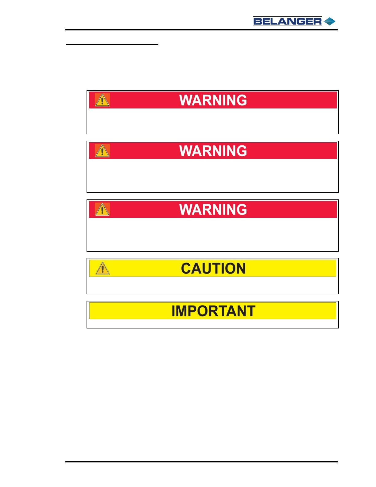
IMPORTANT Safety Information –MUST READ
Safety Warnings
BE SURE TO OBSERVE OPERATING ENVELOPE. EQUIPMENT MAY
START UNEXPECTEDLY. OVERHEAD, ROTATING AND/OR MOVING
COMPONENTS COULD RESULT IN SERIOUS INJURY OR DEATH.
BE AWARE OF FOREIGN OBJECTS IN THE AREA SURROUNDING A
ROTATING PIECE OF EQUIPMENT. OBJECTS MAY BECOME TANGLED
WITH EQUIPMENT AND COULD RESULT IN SERIOUS INJURY OR
DEATH.
CONSULT A TRAINED ELECTRICIAN. ONLY TRAINED OR AUTHORIZED
INDIVIDUALS KNOWLEDGEABLE IN THE RELATED PROCEDURES
SHOULD INSTALL, INSPECT, MAINTAIN OR SERVICE THIS
EQUIPMENT.
BE AWARE OF HAZARDS ASSOCIATED WITH EQUIPMENT INSTALLED
ON THE FLOOR THAT MAY BE A TRIP HAZARD.
BE SURE TO SAVE THESE INSTRUCTIONS.
It is imperative to your safety and the safety of others to always follow
safe work procedures.

Cube®Installation & Startup
1-6 Belanger, Inc. * PO BOX 5470. * Northville, MI 48167-5470 * Ph (248) 349-7010 * Fax (248) 380-9681 1MANUL963
Chapter 1 Introduction
UL Information
This applies when an optional door controller is installed
To reduce the risk of severe injury or death to persons all material and
instructions intended for Belanger® system and door operator shall be
read and comprehended. If materials/instructions are not present, they
must be obtained prior to beginning installation/modification.
The Door Control System shall not be installed at locations that don’t
provide a Service entrance. The service opening shall be labeled as an
exit and placards installed on vertical door indicating no pedestrians.
The Belanger® system is not intended for use as source of preventing
injury to persons, nor is it intended for entrapment or obstruction
protection as described in UL 325. This equipment is intended to
enhance the system by signaling the doors desired position but be
overridden by operator’s safety features. The operator that is in direct
control of the door must independently provide entrapment protection
in accordance with UL325. Installation of the Belanger® system shall
not interfere with primary or secondary entrapment protection, nor
interfere with any provided safety features of the door operator.
The installer shall evaluate the existing/new operator requirements for
maintaining UL325 compliance, Examples include loss of being in
accordance when parallel connections are made to up/down buttons,
or loss of being in accordance when upward motion brings door
within 2 feet of a solid object, etc.

Cube®Installation & Startup
1MANUL963 Belanger, Inc. * PO BOX 5470. * Northville, MI 48167-5470 * Ph (248) 349-7010 * Fax (248) 380-9681 1-7
Chapter 1 Introduction
Scope of This Manual
This Introduction Section is intended to:
•Address the installation portion only.
•Help you to understand how the installation manual is organized.
•Encourage planning and organization.
•Address safety issues.
Installation Manual
This is the manual that covers the installation and initial startup of a Cube®system. In this
manual there is very little content as to the operation, maintenance, troubleshooting and
replacement parts of the Cube® system. For those items please refer to the Cube®
Maintenance manual and any other supplied support documents.
How the Manual is Organized
The installation manual starts off with a "punch list" of activities that must be performed during
the installation phase. The list is fairly comprehensive and provides a general order in which
the tasks should be completed to minimize installation time.
This list also acts as a directory for the remainder of the manual. Now is a good time to review
the Recommended Installation Sequence checklist in chapter 2.
The last section of the installation manual is concerned with initial startup. A checklist format
is provided as a walk- through of starting up and fine tuning the Cube®system.
Planning and Organization
The installation manual assumes that your Belanger® Representative has already visited the
site, taken measurements, and quite possibly sent drawings showing equipment locations.
The installation manual also assumes that all these items have been thoroughly reviewed by
the site General Contractor and Owner. If that is not the case, now is the time to do so. For
your convenience, the "Getting Started" section reiterates some of the critical points of a
Cube®installation. Primarily, the “Getting Started” section addresses equipment placement
and electrical considerations to ensure the Cube®system is installed successfully. If there
is a planning question not covered in this manual, please contact your Belanger®
Representative immediately.
Ensure a Safe Work Environment
The job site can be a hectic place. Often deadlines control the pace. Please keep, Job Site
Safety, in mind at all times. Proper use of all safety gear (safety glasses, hard-hats, footwear,
shields, guards, etc.) is imperative. Be aware of electrical concerns (exposed conductors,
extension cords, proximity to water, power tool maintenance, etc.). Be sure to obey OSHA
Lockout/Tagout procedures (Refer to 29 CFR 1910.147 and the example in 29 CFR
1910.147 Appendix A) and that everyone on site understands this process. Rigging (forklift
operation) is another concern. Minimize slip, trip, and fall potentials consistently. In short, be
aware of OSHA considerations, in addition to rules and regulations put in place by your local
authorities.
It is imperative to your safety and the safety of others to always follow safe
work procedures.
Cube®Installation & Startup
1-8 Belanger, Inc. * PO BOX 5470. * Northville, MI 48167-5470 * Ph (248) 349-7010 * Fax (248) 380-9681 1MANUL963
Chapter 1 Introduction
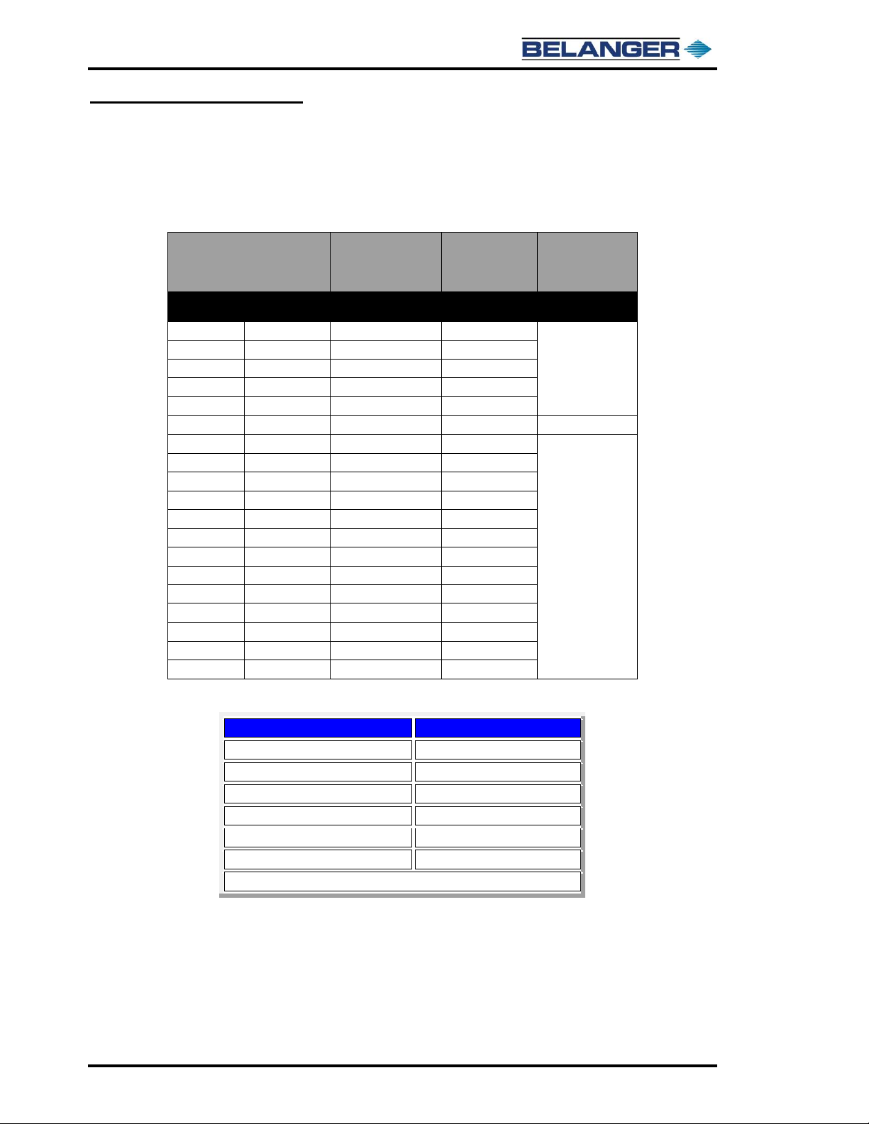
Torque Values
The following chart represents torque values for Grade-5, Stainless Steel Grade 18-8, and Grade-8
fasteners, which are the common fasteners used on Belanger® equipment.
Information provided by Engineers Edge
Torque Values = FT - lbs.
SAE Grade 5
120,000 PSI
Medium Carbon
Heat Treated Steel
Stainless Steel
Grade 18-8
SAE Grade 8
150,000 PSI
Medium Carbon
Alloy Steel
Bolt Size
Inches
Coarse
Threads/Inch
Torque Values
(FT*LBS)
Torque Values
(FT*LBS)
Torque Values
(FT*LBS)
#10
24
NA
2
1/4
20
10
6
5/16
18
19
11
3/8
16
33
20
7/16
14
54
31
1/2
13
78
43
120
9/16
12
114
57
5/8
11
154
93
3/4
10
257
128
7/8
9
382
194
1
8
587
287
1 1/8
7
794
NA
1 1/4
7
1105
NA
1 3/8
6
1500
NA
1-1/2
6
1775
NA
1 5/8
5.5
2425
NA
1 3/4
5
3150
NA
1 7/8
5
4200
NA
2
4.5
4550
NA
Bolt Torque Factors
LUBRICANT OR PLATING
TORQUE CHANGES
Oil / Anti-seize
Reduce torque 15% to 25%
Dry Film (Teflon™ or moly based)
Reduce torque 50%
Dry Wax (Cetyl alcohol)
Reduce torque 50%
Chrome plating
No change
Cadmium plating
Reduce torque 25%
Zinc plating
Reduce torque 15%
Information provided by raskcycle.com
Torque values should be reduced if using lubricants such as anti-seize.
Other manuals for CUBE
1
Table of contents
Other Belanger Industrial Equipment manuals


