Anywave ACT-5X User manual

ANYWAVE
ACT-5X
ATSC Exciter/Translator
User Manual
Version 3.0
ACT-5XU-A -C
May 7, 2015

ACT-5X Exciter User Manual
Version 3.0 05/07/2015 Page 2 of 26
Copyright Notice
Copyright © Anywave Communication Technologies, Inc. 2013, All rights reserved.
No part of this publication may be reproduced, translated, transcribed, stored in a retrieval system, or
transmitted into any form or by any means, without the express written permission of Anywave
Communication Technologies, Inc.
Disclaimer
Information provided by Anywave Communication Technologies is believed to be accurate
and complete; however, no liability can be assumed for its use. The information contained in
this publication is subject to change without notice.
Anywave Communication Technologies Inc.
300 Knightsbridge Parkway, Suite 150, Lincolnshire, IL 60069
Tel: +1 (847) 415-2258
Fax: +1 (847) 415-2112
http://www.anywavecom.com/en/

ACT-5X Exciter User Manual
Version 3.0 05/07/2015 Page 3 of 26
Contents
1 Product Appearance ..........................................................................................4
1.1 Front Panel.....................................................................................................4
1.2 Back Panel .....................................................................................................5
2 Operation Specifications...................................................................................6
3 Menu.................................................................................................................8
3.1 Initialization...................................................................................................8
3.2 Query Mode ...................................................................................................8
3.3 User Menu....................................................................................................10
3.4 Advanced Menu ...........................................................................................15
3.4 Web Interface...............................................................................................19
4 Connection......................................................................................................21
4.1 Connect the Transmitter...............................................................................21
4.2 Start ADPC function ....................................................................................21
5 Troubleshooting ..............................................................................................23
5.1 TS Input (Exciter Mode)..............................................................................23
5.2 Tuner Input (Translator Mode) ....................................................................23
5.3 GPS..............................................................................................................24
5.4 ADPC...........................................................................................................24
5.5 Other Problems ............................................................................................25

ACT-5X Exciter User Manual
Version 3.0 05/07/2015 Page 4 of 26
1 Product Appearance
1.1 Front Panel
LCD:
40×2 LCD with power saving backlight
6 Buttons:
Left, Right, Up, Down, OK, ESC
6 LEDs:
When in Exciter mode:
LED_TS1: Green light on indicates TS1 is selected and the input TS signal is OK
LED_TS2: Green light on indicates TS2 is selected and the input TS signal is OK
LED_TSErr: Red light on indicates the selected input signal has error (Refer to Chapter 5)
When in Translator mode:
LED_ TS1: Green light on indicates the synchronization of input RF signal is OK
LED_TS2: Green light on indicates the equalization of input RF signal is OK
LED_TSErr: Red light on indicates there is synchronization error or equalization error
In both Exciter and Translator mode:
LED_ GPS: Green light on indicates GPS connected and locked
LED_ RFON: Green light on indicates system ready and RF on
LED_ SysErr: A flashing red LED indicates the presence of a system error (Refer to Chapter 5)
A solid red LED indicates the unit is in "Local (LCL)" control mode, and when this
LED is off, this indicates that the unit is in "Remote (RMT)" control mode
1 BNC connector:
RFMON: Reserved

ACT-5X Exciter User Manual
Version 3.0 05/07/2015 Page 5 of 26
1.2 Back Panel
RF_IN_A: Feedback signal, sampled after the band-pass filter (-5 to -15dBm)
RF_IN_B: Feedback signal, sampled before the band-pass filter (-5 to -15dBm)
AGC_IN: Feedback DC voltage forAGC control (0-5VDC)
RF_MON: Loop out of [RF_OUT] for monitoring (-25 dB below RF_OUT)
RF_OUT: Main RF signal output N-type female (nominal 0 dBm output)
DRYLOOP (RS232): Dry loop for remote control
REMOTE (RS232): Serial port for remote control
REMOTE (RJ45-B): 10M/100M Ethernet for remote control
TSoIP (RJ45-A): Reserved
10M_IN: 10 MHz input from external GPS receiver
1PPS: 1 PPS input from external GPS receiver
TS_IN_1: The first port of TS inputs, DVB-ASI only
TS_OUT_1: Loop out of [TS_IN_1] for monitoring
TS_IN_2: The second port of TS inputs, DVB-ASI only
TS_OUT_2: Loop out of [TS_IN_2] for monitoring
TUNER_IN: Received RF signal input, N-type female

ACT-5X Exciter User Manual
Version 3.0 05/07/2015 Page 6 of 26
2 Operation Specifications
Environment
Operating Temperature: -10 ~ 50 oC
Operating Humidity: ≤95%
Atmospheric Pressure: 86 kPa ~ 106 kPa
Power Supply
Voltage: 88 ~ 264 VAC
Frequency: 50 / 60 Hz
Inputs/Outputs
RF_IN_A /RF_IN_B
Connector: BNC female
Impedance: 50 Ω
Level: -30 dBm ~ 0 dBm
Recommended range: -15 dBm ~ -5 dBm
Location: Back Panel
AGC_IN
Connector: BNC female
Impedance: 50 Ω
DC Voltage: 0 V ~ 5 V
Location: Back Panel
RF_OUT
Connector: N-type female
Impedance: 50 Ω
Level: -25 dBm ~ +5 dBm
VSWR: > 15 dB
Location: Back Panel
RF_MON (loop out of [RF_OUT])
Connector: BNC female
Impedance: 50 Ω
Level: 25 dB below [RF_OUT]'s output level
Location: Back Panel
10M_IN
Connector: BNC female
Impedance: 50 Ω
Level: AC-coupled, VP-P ≥300 mV
Location: Back Panel

ACT-5X Exciter User Manual
Version 3.0 05/07/2015 Page 7 of 26
1PPS (input)
Connector: BNC female
Impedance: 50 Ω
Level: 3.3 V-TTL
Input trigger: Positive Transition
Location: Back Panel
TS_IN_1/ TS_IN_2
Connector: BNC female
Impedance: 75 Ω
Level: See Table 1
Location: Back Panel
TS_OUT_1/ TS_OUT_2
Connector: BNC female
Impedance: 75 Ω
Location: Back Panel
TUNER_IN
Input level range: -80 dBm ~ - 15 dBm
Input connector: N-Type female, 50 Ω
Table 1 ASI Input Specifications
No
Content
Unit
Value
1
Input Level
mv
200
2
Positive Transition (20%~80%)
ps
1200
3
Negative Transition (20%~80%)
ps
1200
4
Deterministic Jitter
%
10
5
Random Jitter
%
8
Note
1) The electrical interface characteristics are measured under normal conditions. Values may vary.
2) Operating in abnormal conditions may result in damage to the equipment. Long operating hours in
severe environments may reduce the reliability of the entire system, which may cause permanent
damage to equipment. Make sure all electrical interface characteristics and environmental parameters
are within the defined range listed above before operating this equipment.

ACT-5X Exciter User Manual
Version 3.0 05/07/2015 Page 8 of 26
3 Menu
3.1 Initialization
Connect the power supply of the ACT-5X and then turn on the exciter/translator via the power switch
located on the rear of the unit. The initialization process takes about 5 seconds to finish while the RF
output level gradually increases to the pre-set value.
The ACT-5X platform can operate in both Translator and Exciter modes. In Translator Mode, the unit
receives an RF signal (via the TUNER_IN rear panel connection) and feeds this to an internal tuner that
performs a demodulation at the specified receive frequency, followed by a modulation at the specified
transmit frequency. In Exciter Mode, the unit operates upon a TS signal (received via one of the ASI rear
panel BNC inputs, TS_IN_1 or TS_IN_2) and performs a modulation at the specified transmit frequency.
The first step after turning on the unit is to confirm the desired operating mode (Exciter or Translator)
according to your application. The “INPUT” setting located under the “SYSTEM” submenu should be set
to “TS” for exciter mode or “TUNER” for translator mode. Please see Table 6 below for details.
3.2 Query Mode
Query mode is a mode which displays parameters and status of the exciter/translator. There are three
pages in query mode. Press the "Right" or "Left" button to switch between different pages which are
shown in Table 2 through Table 4 below.
Note: The settings shown in the tables below for illustration purposes only and may be different from
those in actual use.
Table 2 First Page in Query Mode (EX mode)
FWD
TSNR
LID
UID
100%
38.5
43.5
44.0
Table 3 Second Page in Query Mode
Table 4 Third Page in Query Mode
RXFREQ
TXFREQ
AGC
GPS
CTRL
ADPC
653M
653M
OFF
LOCK
RMT
OFF
INPUT
STA
RSSI
RSNR
TEMP
TS1
OK
-45
30.75
104.90℉

ACT-5X Exciter User Manual
Version 3.0 05/07/2015 Page 9 of 26
Note:
1) The "TSNR", "LID" and "UID" in Table 2 are the measurements of feedback signal quality. This
feedback signal could be from a transmitter or the exciter/translator itself and its input range is -30
dBm to 0 dBm (Recommended range is -15 dBm to -5 dBm). These measurements are derived from
the After-filter Feedback Signal connected to the rear port [RF_IN_A] BNC connector. If there is no
signal connected, these readings will not be available or not valid. The "TSNR" is measured with
equalization on. It takes about 10 seconds to get the first reading on "TSNR", and about 3 seconds to
get the first reading of "LID" and "UID". After averaging, the displayed upper limit on the "TSNR" is
about 39 dB and about 54 DB for the IMD metrics.
2) The "RSNR" and "RSSI" in Table 3 are status of the signal from the tuner when working in Translator
Mode. And the "RSNR" is measured with equalization on. Therefore if there is no signal connected to
port "RF_IN", these readings will not be available or not valid.
3) The "CTRL" status in Table 4 indicates "RMT" (Remote) mode or "LCA" (Local) mode. When in
"LCA" mode, the exciter/translator can only be controlled by the front panel interface and when in
"RMT" mode, settings from the front panel keyboard are ignored - with the exception of
"RMT"/"LCA" setting - and while in RMT mode, only commands from remote control interface, such
as the WEB or serial port, are processed.

ACT-5X Exciter User Manual
Version 3.0 05/07/2015 Page 10 of 26
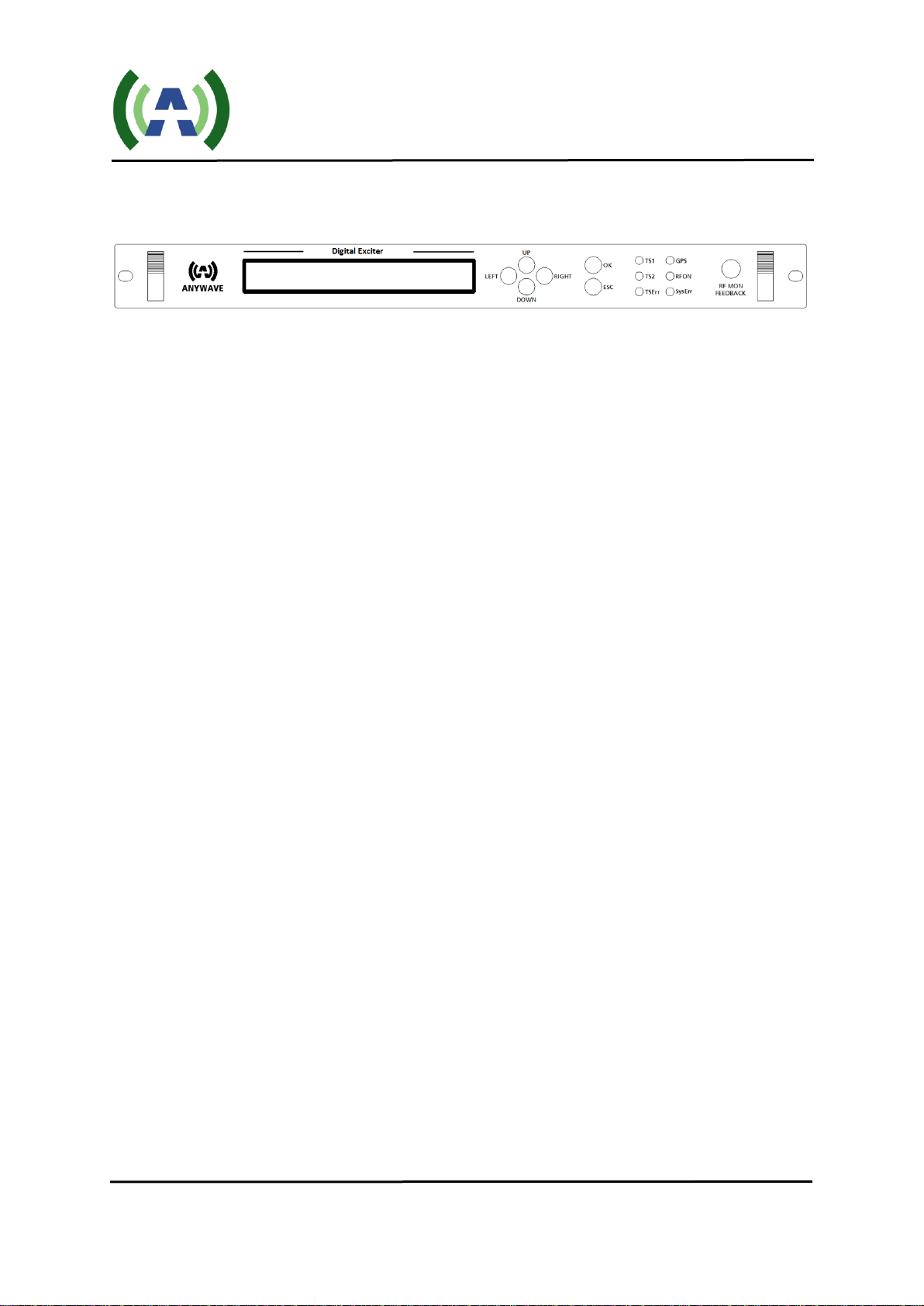
3.3 User Menu
In Control mode, the user may modify configuration settings of the exciter/translator. There are two
levels of control, the User Menu and the Advanced Menu. To enter the User Menu, press both the "Left"
and "Right" buttons at the same time while in query mode. The User Menu in control mode is shown
below in Table 5. In the next section we will present theAdvanced Menu.
Table 5 Main Menu
Welcome to setting interface!
*SYSTEM
RF
FREQ
MODE
CONFIG
The Main User Menu consists of 5 sub-menus: SYSTEM, RF, FREQ, MODE and CONFIG.
Once at the main menu, press the "Left" or "Right" buttons to move the cursor and navigate to the
desired sub-menu. Once the cursor is positioned just above the desired sub-menu, press the "OK" button to
enter the target sub-menu. When in the corresponding sub-menu, press "Left" or "Right" button to move
the cursor to the target parameter and then press the "Up" or "Down" buttons to select different options
from the drop-down boxes. Once you have selected the desired option, press the "OK" button to apply
and save, or press the "ESC" button to skip the changes and return to the upper menu.
All the parameters of sub-menus are shown in Tables 6 through Table 10 respectively.
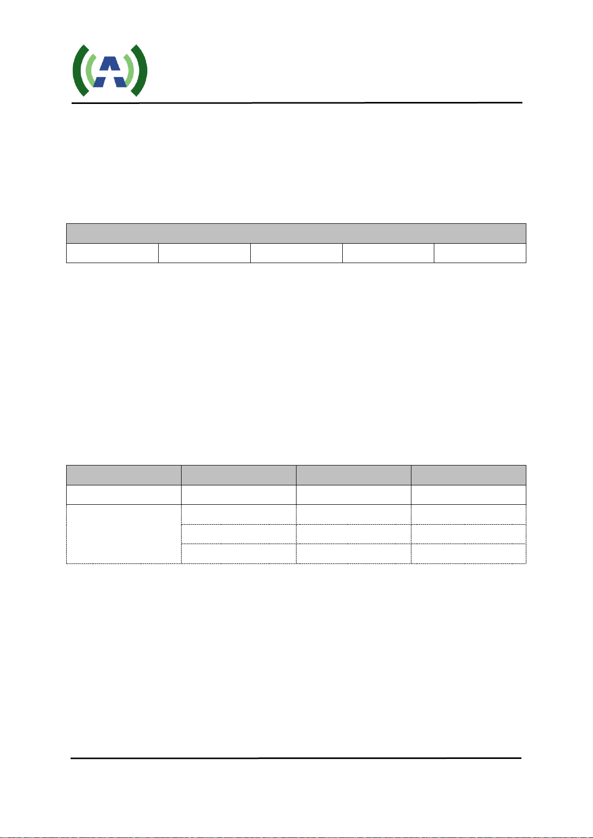
Table 6 System Menu
CTL
ADPC
INPUT
Default
RMT
OFF
TS
Options
RMT
OFF
TS
LCA
UPDATE
TUNER
HOLD
Note:
1) The "CTL" (Control) setting has two options, "RMT" (Remote) and "LCA" (Local). The
exciter/translator can be switched between these two modes only via the front panel interface. When
in "Local" mode, the exciter/translator can only be controlled by the front panel interface and all
commands from serial port or WEB are ignored. When in "Remote" mode, settings from the front
panel keyboard are ignored - with the exception of "RMT"/"LCA" setting, and only commands from
the remote control interface, such as serial port or WEB, are processed. Notice that LED "SysErr"
remains on all the time in "LCA" mode, and only indicates a SysErr when it is flashing.

ACT-5X Exciter User Manual
Version 3.0 05/07/2015 Page 11 of 26
2) The "ADPC" parameter in the "SYSTEM" sub-menu has options of "UPDATE", "HOLD" and
"OFF". If option "OFF" is selected, the ADPC function will be turned off (no correction applied). If
option "HOLD" is selected, the exciter will apply the last stored linear and non-linear correction
coefficients. If both feedback signals are connected properly and option "UPDATE" is selected, this
will cause the exciter to run the Adaptive Digital PreCorrection (ADPC) function, automatically
computing coefficients for both the linear and non-linear pre-correction for the entire transmission
system including the distortion of both transmitter and band-pass filter. This process takes about 8 to
10 minutes, after which the computed corrections are automatically store in nonvolatile memory.
Please refer to Chapter 4 for detailed information.
3) The "INPUT" setting has two options, "TUNER" (Translator Mode) and "TS" (Exciter Mode). When
"TUNER" is selected, the unit functions as a translator which receives an off-air RF signal with a
tuner, and then performs the demodulation, followed by a modulation. When "TS" is selected, the unit
functions as an exciter which receives an ASI TS signal directly and performs only the modulation.

ACT-5X Exciter User Manual
Version 3.0 05/07/2015 Page 12 of 26
Table 7 RF Menu
RF
POWER
AGC
LVL
REF
Default
ON
+0.00
OFF
000
000
Options
ON
-25.00
OFF
000~255
000~255
OFF
-24.95
ON
-24.90
...
...
...
+4.90
+4.95
+5.00
Note:
1) The RF parameter in the “RF” sub-menu turns the RF output of the exciter/translator ON or OFF.
2) The POWER parameter specifies the RF output power level in dB (in the range of -25 to +5 dBM,
note: typical exciter/translator output level is 0 dBm).
3) The "AGC" parameter in the "RF" sub-menu is used to engage or disengage the exciter/translator
system-level automatic gain control. AGC has options "ON" and "OFF". "LVL" and "REF" are
decimal numbers whose range is from 0 to 255. "LVL" is the reading of the DC voltage from Port
[AGC_IN] which reflects the AGC feedback signal level, and "REF" is the reference value (or target)
of the AGC function. When AGC is turned ON for the first time, the "LVL" will be saved
automatically to "REF" as a reference. So if the AGC feedback signal level changes due to
temperature differences or mismatch impedance, etc., the reading of "LVL" will be different from that
of "REF", and the AGC function starts to slowly adjust the output level of the exciter/translator to
approach to the pre-set reference level. TheAGC adjustable range is from +1 dB to -10 dB.

ACT-5X Exciter User Manual
Version 3.0 05/07/2015 Page 13 of 26
Table 8 FREQ Menu
RXFREQ
TXFREQ
Hz
Default
653M
653M
+00000
Options
473M
473M
-50000
479M
479M
-49999
485M
485M
-49998
...
...
...
...
...
...
...
...
...
875M
875M
+49998
881M
881M
+49999
887M
887M
+50000
Note:
1) The RXFREQ parameter in the “FREQ” sub-menu specifies the off-air receiver channel frequency for
the internal tuner to receive the proper over-the-air UHF channel. This setting is used when the unit is
configured to operate as a Translator (“INPUT” set to TUNER) and is ignored when the unit is
configured to operate as an Exciter (“INPUT” set to TS).
2) The TXFREQ parameter in the “FREQ” sub-menu specifies the channel frequency for the modulated
RF output signal of the exciter/translator.
3) The "Hz" parameter provides a direct adjustment (offset) of the frequency of the TXFREQ RF output
signal. The range is -50,000 Hz to +50,000 Hz, with steps of 1 Hz. This feature is designed for up to
50 kHz spectrum shift as ATSC standard required, or adjustment of the output frequency for carrier
accuracy.
Table 9 MODE Menu
8VSB
Note:
1) The MODE sub-menu provides settings for the modulation mode selected. The ACT-5X
Exciter/Translator operates in ATSC Legacy (A/53) mode and as such always displays 8VSB under the
MODE menu. There is an optional ACT-5X series platform that operates as an ATSC MH Translator,
which presents additional parameters under this MODE sub-menu for MH (A/153) configuration.

ACT-5X Exciter User Manual
Version 3.0 05/07/2015 Page 14 of 26
Table 10 CONFIG Menu
*ID
bps
IP
GATEWAY
MASK
UPGRADE
Default
ID: 80H
19200
192.168.001.1
43
192.168.001.0
01
255.255.255.00
0
NO
Options
ID: 00H
19200
***.***.***.*
**
***.***.***.*
**
***.***.***.**
*
NO
ID: 01H
9600
YES
...
38400
ID: FEH
ID: FFH
Note:
1) "IP", "GATEWAY", and "MASK" are used to establish a valid Ethernet connection for remote control
via the REMOTE RJ45 located on the rear panel. The exciter has a built-in WEB GUI which requires
only a standard web browser run by a PC. Simply by entering specified IP address, which is setup in
CONFIG sub-menu, in a browser’s address bar, the login interface will pop up and give user prompts
to input the user name and password. There are two tiers of web interface available. The first “guest”
tier is limited in monitoring and control, allowing users to retrieve information such as SNR and
shoulder measurements, user configuration, and alarms. The guest account is accessed with a user
name and password of "guest" and "guest" (case sensitive). The second “admin” tier provides full
status and control of the exciter/translator and is accessed with a username and password of
"anywavecom" and "anywavecom" (case sensitive).
2) "UPGRADE" is a reserved mode to perform an upgrade of the code inside the exciter/translator unit.

ACT-5X Exciter User Manual
Version 3.0 05/07/2015 Page 15 of 26
3.4 Advanced Menu
To enter the Advanced Menu, first enter the User Menu by pressing the both "Left" and "Right"
buttons at the same time to arrive at the menu shown below.
Table 11 User Menu
Welcome to setting interface!
*SYSTEM
RF
NETWORK
MODE
CONFIG
Then, press both the "Up" and "Down" buttons at the same to enter Advanced Menu, as shown
below.
Table 12 Advanced User Menu
Welcome to advanced interface!
*AD1
MUTE
TX_EX
DPD
LATCH
SN
PAC
Table 13 through Table 19 show the corresponding sub-menus.
Table 13 AD1 Menu
PCRL
Sw_Up
Sw_Down
SW_RT
NET
Default
1
OFF
OFF
03
AUTO
Options
0: Null packet
deletion ON
but NO PCR
ON
ON
03~FF
AUTO
1: Null packet
deletion ON
and PCR ON
OFF
OFF
10M
2: NO null
packet deletion
and NO PCR
100M
3: NO null
packet deletion
but PCR ON

ACT-5X Exciter User Manual
Version 3.0 05/07/2015 Page 16 of 26
Note:
1) "PCRL" in Advanced User Menu contains 3 bits. Its default value is 1 which means both PCR
function and NULL packet deletion is turned on. It’s only applicable in Legacy mode. In MH mode,
all input streams remain untouched.
a) Bit2 is the switch of Insert-NULL-Packet.
It's not used now (reserved) because when TS rate is lower than desired rate and FIFO is Almost
Empty (less than 2.5% of its capacity), if the system does not insert NULL packets into the
stream automatically, the whole FIFO will be reset and lose more useful bytes.
b) Bit1 is the switch of Delete-NULL-Packet.
When value is "0":
If FIFO is Half Full (higher than 50% of its capacity), then the system will DELETE all new
coming NULL packets from the stream automatically, until FIFO is less than 50%.
When value is "1":
If FIFO is Half Full, the system will NOT DELETE any new coming packets.
c) Bit0: The switch of Program Clock Reference Correction function
"1" means PCR function is ON;
"0" means PCR function is OFF
2) "Sw_Up" and "Sw_Down" are a pair of switches which control the "Slow Up / Down" function. If
"Sw_Up" is "ON", when there is a power raise, it will go up gradually. Likewise if "Sw_Down" is
"ON", when there is a power decrease, it will go down gradually too. This "Slow Up / Down"
function is designed for safety consideration and to prevent the transmitter connected from any
possible damage due to the dramatic change of power.
3) SW_RT establishes the RF ramp up time, with larger numbers producing a slower ramp to full output
power.
4) NET allows the selection of 10M, 100M, or Auto to optimize networking connections with existing
local networks.
Table 14 MUTE Menu
M_TS
Default
0
Options
0
1
Note:
1) "M_TS" is the selection of MUTE/PRBS on loss/failure of RF input reception.
M_TS =1: RF Mute on loss/failure of RF input reception.
M_TS =0: Output PRBS instead on loss/failure of RF input reception.

ACT-5X Exciter User Manual
Version 3.0 05/07/2015 Page 17 of 26
Table 15 TX_EX Menu
RC_CMD
FWD_CAL
CW
RST
Default
Other
OK
OFF
NO
Options
Other
OK
OFF
NO
IO
CAL
ON
YES
Note:
1) “RC_CMD” determines where the TX On/Off command comes from:
“IO” means from Pin 1 of Dry Loop;
“Other” means from either Serial or Web interface.
2) "FWD_CAL": Default value is "OK". "FWD_CAL" is used to calibrate the 100% FWD power level.
Table 16 DPD Menu
PDT
CFR
ADPC
FSSI
Default
5
F
OFF
0%~100%
Options
0~F
0~F
HOLD
UPDATE1
UPDATE2
UPDATE3
Note:
1) "PDT" is the pre-set time for ADPC function which ranges from 0x0 to 0xF, and recommended value
is 0x5 which means about 7 minutes in "UPDATE3" part and about 10 minutes for the entire ADPC
process (all 4 steps together).
2) "CFR" is the pre-set crest factor reduction level which ranges from 0x0 to 0xF. The lower the
parameter's value is, the harder the reduction of crest factor will be. And 0xF means bypass the whole
CFR function (No reduction at all).
Note: If ADPC (Pre-correction) is ongoing, the system will disable automatically the CFR
function (clipping) and will only resume the function afterADPC is finished.
3) "ADPC" here has the same function as that in control mode (default user menu) but separates into 3
steps. And the control here and there (default user menu) sync up to each other. All 3 steps still have
to be run in strict sequence to get a complete compensation done. However going step by step gives it
a chance to monitor each step's performance more closely. Among all 3 steps, "UPDATE1" is to
compensate the linear distortion before band-pass filter, and "UPDATE2" is for the linear distortion
after band-pass filter. "UPDATE3" is for both linear and non-linear distortion in the whole
transmitting system (include both the power amplifier and the band-pass filter).

ACT-5X Exciter User Manual
Version 3.0 05/07/2015 Page 18 of 26
4) "FSSI" is indicator of feedback signal strength and its range is from 0% to 100%.
At +5 dB level, FSSI=100%.
At -5 dB level, FSSI=75%
At -15 dB level, FSSI=50%
At -20 dB level, FSSI= 25%
*The readings listed above are typical values. There may be variations on different frequencies or
different units. Overall the recommended level of feedback signal is -15 dBm to -5 dBm.
When FSSI is less than 20% or higher than 75%, the reading will keep flashing, indicating the
feedback level may need to be adjusted.
Table 17 Latch Menu
RESET
U1
U2
RF
GPS
TS
SYS
1PPS
SFN
Default
OK
0
0
0
0
0
0
0
0
Options
OK
0
0
0
0
0
0
0
0
CLR
1
1
1
1
1
1
1
1
Table 18 SN Menu
SN
GUI_KEY
Default
0000000000000
00000000
Options
Table 19 PAC Menu
Vol_9
Vol_50
Cur_50
PA_FWD
PA_REF
881_GV
VSWR
PA_TEMP
PA__LVL
CUR2_50
Value
Content
Voltage
of 9V
DC
supply
Voltage
of 50V
DC
supply
Current
of 50V
DC
supply
Forward
power of
PA
Reflected
power of
PA
Grid
Voltage
Voltage
standing
wave
ratio
Temperature
of PA
PA rated
power
Current 2
of 50V
DC supply
Note:
1) CUR2_50 is only applicable when rated power is 200W or higher.

ACT-5X Exciter User Manual
Version 3.0 05/07/2015 Page 19 of 26
3.4 Web Interface
The ACT-5X exciter/translator has a built-in web interface accessible via the rear port REMOTE RJ-45
connection, Once networked to your PC, the built-in web interface may be accessed via a web browser
(such as Internet Explorer or Firefox, etc.) by entering the IPaddress of the exciter (default 192.168.1.143,
see Table 10 in section 3 for changing the default IPaddress).
Launching a web browser and entering the exciter/translator IPaddress (192.168.1.143) will bring up the
following login window.
There are two tiers of web interface available. The first “guest” tier is limited in monitoring and control,
allowing users to retrieve information such as SNR and shoulder measurements, user configuration, and
alarms. The guest account is accessed with a user name and password of "guest" and "guest" (case
sensitive). The second “admin” tier provides full status and control of the exciter/translator and is accessed
with a username and password of "anywavecom" and "anywavecom" (case sensitive).
The screenshots below highlight the status and control available via the guest and admin web interfaces.
guest web interface

ACT-5X Exciter User Manual
Version 3.0 05/07/2015 Page 20 of 26
admin web interface
Table of contents
Other Anywave Electronic Dictionary manuals