AOHUA VET-OR1200HD User manual


For veterinary use only -i -
-
Shanghai AOHUA Photoelectricity Endoscope Co., LTD.
Address: No. 66, Lane 133, Guangzhong Road, Minhang District, Shanghai, 201108, P.R.China
Zip code : 201108
Tel : +86-21-67681019
Fax : +86-21-67681019
Website : www.aohua.com
Important information — Please Read Before Use
⚫Before use, thoroughly review this manual.
⚫Please keep all instruction manuals in a safe, accessible place.
⚫Contact AOHUA for any questions or comments about this instruction manual.

Contents
For veterinary use only -ii -
-
Important Information — Please Read Before Use 1
Intended use 1
Instruction manual 1
User qualifications 1
Ancillary equipment 1
Instrument compatibility 1
Spare equipment 1
Repair and modification 1
Signal words 2
Dangers, warnings and cautions 2
Labels and symbols 4
Chapter 1 Checking the Package Contents 5
1.1 Checking the package contents list 5
Chapter 2 Nomenclature and Functions 6
2.1 Nomenclature and functions 6
2.1.1 Front panel 6
2.1.2 Rear panel 10
2.2 Product characteristics 13
2.3 Performance characteristics 13
2.4 Specifications 14
2.4.1 Operating environment 14
2.4.2 Interconnected devices 14
2.4.3 Technical specifications 14
Chapter 3 Installation and Inspection 15
3.1 Endoscope imaging processor installation and connection 15
3.2 Inspection of the power supply 17
3.3 Inspection of the examination light 17
3.4 Inspection of the brightness adjustment 18
3.5 Inspection of the monitor display 18
3.6 Inspection of the freeze and release function 18
3.7 Inspection of the operation mode switch (only for VET-OR1200R) 19
3.8 Inspection of the air feeding ………………………………………………………………………. 19
3.9 Inspection of power OFF 19

Contents
For veterinary use only -iii -
-
Chapter 4 Operation 20
4.1 Precautions 20
4.2 Turning the endoscope imaging processor ON 20
4.3 Adjusting the white balance 22
4.4 Panel operation 21
4.4.1 Schematic diagram of panel 22
4.4.2 Examination lamp ignition 22
4.4.3 White balance adjustment 23
4.4.4 Edge enhancement 23
4.4.5 Automatic Gain Control (AGC) 24
4.4.6 Hemoglobin enhancement 24
4.4.7 Freezing the image 25
4.4.8 Image replaying 25
4.4.9 IRIS mode setting 26
4.4.10 Video recording 26
4.4.11 Taking photo 27
4.4.12 Air feeding …………………………………………………………………………………… 27
4.4.13 MODE selection (only for VET-OR1200R)……………………………………………….. 28
4.4.14 Moiré remove (only for VET-OR1200R)…………………………………………………. 28
4.4.15 Switch operation mode (only for VET-OR1200R) ……………………………………… 29 29
4.4.16 Battery usage check (only for VET-OR1200HD-Li) …………………………………… 29
4.5 Termination of the operation 31
4.6 Fuse replacement (only for VET-OR1200HD,VET-OR1200R) ………………………………... 31
4.7 Maintenance, storage and disposal of the imaging processor 32
4.7.1 Maintenance 32
4.7.2 Storage and disposal 33
Chapter 5 Troubleshooting 34
5.1 Troubleshooting 35
5.2 Returning the imaging processor for repair 35
Chapter 6 Other Information 36
6.1 Manufacture date and service life 36
Warranty Card of Product 37

Important Information — Please Read Before Use
For veterinary use only - 1 -
Intended use
The endoscope imaging processors VET-OR1200HD, VET-OR1200HD-Li, VET-OR1200R are intended to
be used with video endoscopes, fiber endoscopes, or rigid endoscopes in endoscopy, endoscopic diagnosis
and endoscopic treatment.
Instruction Manual
This instruction manual should be kept in an accessible place. Before use, thoroughly review this manual
which contains the most appropriate instructions regarding to the maintenance and operation of this
endoscope imaging processor. By following the essentials in this manual during operation and maintenance,
the malfunction rate could be significantly reduced, resulting in extended lifetime of the endoscope imaging
processor.
Any questions about the information provided in this instruction manual or about the endoscope imaging
processor operation and safety regards, contact AOHUA.
User qualifications
If there is an official standard on user qualification to perform endoscopy and endoscopic treatment that is
defined by the medical administration or other official institutions, such as academic societies for endoscopy,
follow that standard.
This device must be operated by a medical practitioner capable of safely performing endoscopy after
operation technique training. This user manual introduces the ideal preparation and inspection procedures. It
is not the detailed instruction for clinical examination and does not intend to familiarize beginners with
endoscopy techniques and medical knowledge.
Ancillary Equipment
The safety of the endoscope imaging processor does not only rely on the endoscope imaging processor itself,
but also relies on its ancillary equipment. To guarantee the compatibility, only the ancillary equipment
manufactured by AOHUA or confirmed by AOHUA is recommended to use.
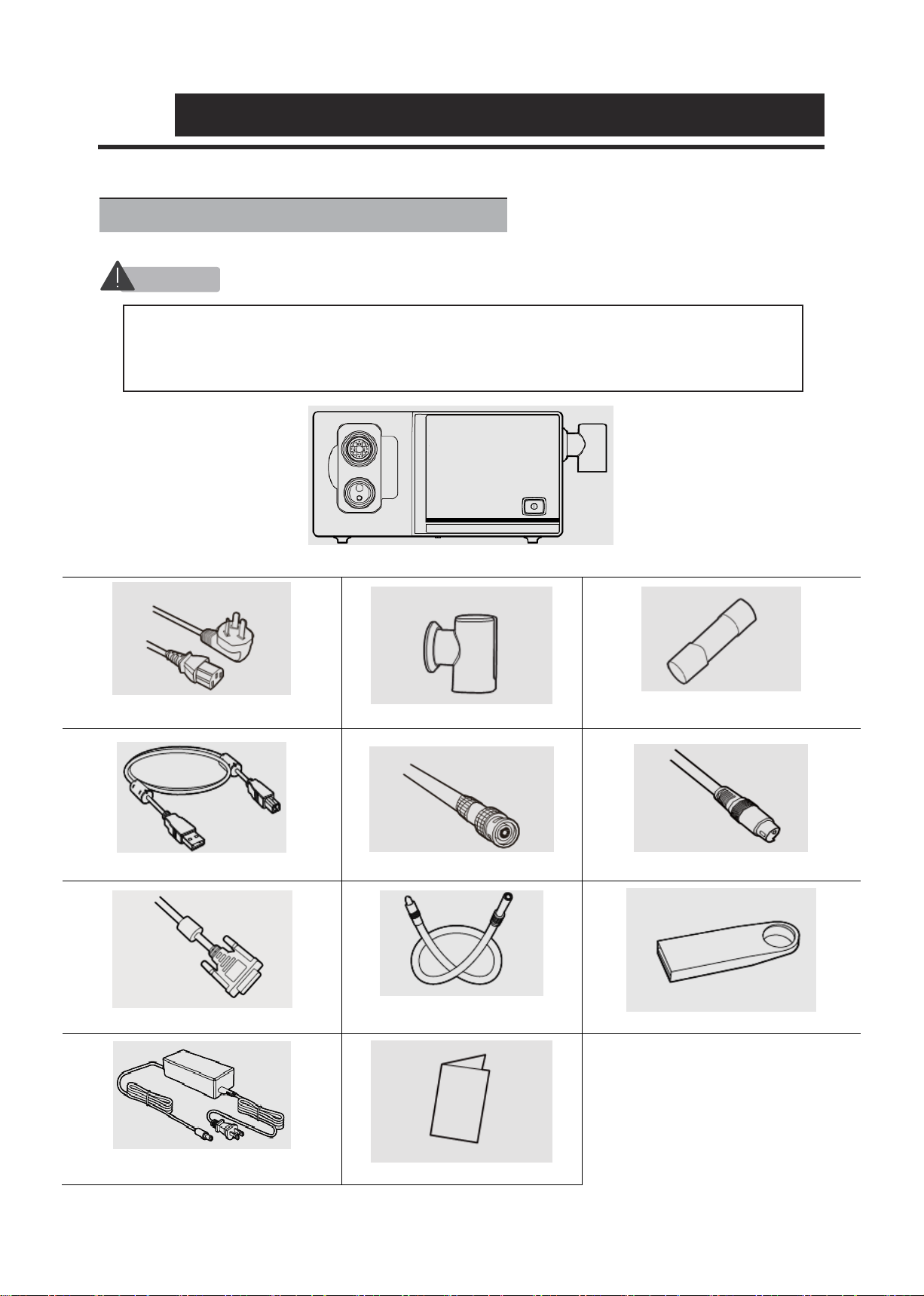
AOHUA prepared the standard accessory and spares list. Please carefully check the items in the package
according to the list provided in Section 1.1, “Checking the package contents list” after purchase. If any item is
missing or damaged, contact AOHUA or distributor immediately. Prior to the first time use of a new
endoscope imaging processor, carefully clean the endoscope imaging processor and accessories.
The endoscope imaging processor and other components should be stored according to the following Section
4.7.2, “Storage and disposal”.
Instrument compatibility
Before use, please refer to “Ancillary Equipment” to confirm that this instrument is compatible with the ancillary
equipment being used. Using incompatible equipment can result in patient or operator injury and/or equipment
damage.
Spare equipment
Be sure to prepare another endoscope imaging processor to avoid interruptions during examination due to
equipment failure or malfunction.
Repair and modification
This instrument does not contain any user-serviceable parts. Do not disassemble, modify or attempt to repair
it; patient or operator injury and/or equipment damage and/or the failure to obtain the expected functionality
may result. Refer to Chapter 5, “Troubleshooting” for solutions of some irregularities. This instrument should be
repaired by AOHUA authorized personnel only.

Important Information — Please Read Before Use
For veterinary use only - 2 -
Signal words
The following signal words are used throughout this manual:
: It indicates an imminently hazardous situation which, if not avoided, will result in
death or serious injury.
: It indicates a potentially hazardous situation, if not be avoided, could result in death
or serious injury.
: It indicates a potentially hazardous situation, if not be avoided, may result in minor or
moderate injury. It may also be used to alert against unsafe practices or potential
equipment damage.
: It indicates additional helpful information.
Dangers, warnings and cautions
Follow the dangers, warnings and cautions below when handling this instrument. This information is to be
supplemented by the dangers, warnings and cautions given in each chapter.
DANGER
⚫Never apply this imaging processor connected with the endoscope to the heart or any area
near the heart.
⚫Never apply an endo-therapy accessory or another endoscope applied to or near the heart to
come in contact with the endoscope connected to this imaging processor.
⚫Strictly observe the following precautions. Failure to do so may put the patient and the medical
personnel in danger.
−When the instrument is used to examine a patient, do not allow metal parts of the
endoscope or its accessories to touch metal parts of other system components.
−Keep fluids away from all electrical equipment. If fluids are spill on or into the unit, stop
operation immediately and contact AOHUA.
−Avoid preparing, inspecting or using the instrument with wet hands.
⚫Never install and operate the endoscope imaging processor in location where:
−The concentration of oxygen is high.
−Oxidizing agent (such as nitrous oxide (N2O)) or flammable anesthetics are present in the
atmosphere.
−Flammable liquids are near.
DANGER
CAUTION
NOTE

Important Information — Please Read Before Use
For veterinary use only - 3 -
⚫This device must be operated by a medical practitioner capable of safely performing
endoscopy after operation technique training. Do not use this instrument for any purpose other
than its intended use.
⚫Do not use the instrument in any place where it exposed to strong electromagnetic radiation.
Otherwise, this may impair the performance of the instrument.
⚫Always set the brightness to the minimum required level, as strong light like xenon light may
cause patient burns.
⚫Avoid observing in proximity to the mucosa for an extended period. It may cause patient burns.
CAUTION
⚫This instrument shall be used with auxiliary equipment or accessories complied with relevant
EMC standards for safety reason. Otherwise, performance of the imaging processor may be
affected.
⚫Portable or mobile phones may cause radio interference to this instrument. Relocating the
imaging processor or provide shield to the location if the radio interference occurs.
⚫Do not connect or disconnect the endoscope connector while this instrument is turned ON.
This action may destroy the instrument.
⚫When the instrument is used with other non-medical auxiliary equipment, such as video
recorder and printer, the isolated transformer or insulating socket must be used to ensure the
safety.
⚫Do not use a sharp or hand object to press the buttons on the front panel. This may damage
the buttons.
⚫Avoid applying excessive force to the connectors, as this may damage the instrument.

Important Information — Please Read Before Use
For veterinary use only - 4 -
Labels and Symbols
Type BF applied part
Protective earth(ground)
Caution
Equipotentiality
Refer to instruction manual
Date of manufacture
Manufacturer
Keep dry
Use-by date
Keep away from sunlight
Serial Number
Fragile, handle with care
Stacking limit by number
Temperature limit
This way up

01 Checking the Package Contents
For veterinary use only - 5 -
Endoscope imaging processor VET-OR1200HD / VET-OR1200HD-Li / VET-OR1200R
Power cord
(only for VET-OR1200HD, VET-OR1200R)
White balance cap
Fuse
(only for VET-OR1200HD, VET-OR1200R)
Type D USB cable
BNC cable
S-video cable
DVI cable
Light guide cable
(only for VET-OR1200R)
Portable memory
Battery adapter
(only for VET-OR1200HD-Li)
User manual
1.1 Checking the package contents list
CAUTION
⚫Check all items in the package against the components listed below. If any component is missing
or damaged, do not use the item; please contact AOHUA immediately. Accessories below in the
list are only for the reference. Please refer to the packing list/ shipping list included in each
shipment.
⚫

02 Nomenclature and Functions
For veterinary use only - 6 -
2.1.1 Front panel
oVET-OR1200HD, VET-OR1200HD-Li
(Figure 2.1.1a Front panel of VET-OR1200HD, VET-OR1200HD-Li)
No.
Nomenclature
Description
1
W.B Button
press it for 2~4 seconds to perform white balance adjustment.
2
IRIS mode Button
Press to select average IRIS mode or peak IRIS mode.
3
AGC Button
Press this button to adjust the endoscopic image brightness within
four levels.
4
ENH button
Press to switch image edge enhancement within 0,1,2,3 four levels.
5
Photo Button
Press this button to freeze current endoscopic mage and store in
the portable memory. (A portable memory needs to be inserted to
activate this function)
6
Record Button
Press this button to capture video and store in the portable
memory. (A portable memory needs to be inserted to activate this
function).
7
Light Button
Press this button to ignite or extinguish the examination lamp.
8
White Balance Cap
Insert the distal end of the endoscope to perform white balance
adjustments.
Warning: No objects are allowed to be hanged on the white balance
cap.
2.1 Nomenclature and Functions

02 Nomenclature and Functions
For veterinary use only - 7 -
No.
Nomenclature
Description
9
Brightness Adjustment
Button
Press the “+”/ “-” button to increase/decrease emitting light
brightness.
10
Power Switch and Indicator
Press to turn the endoscope imaging processor ON or OFF.
11
USB port
Insert compatible portable memory into this port to save images and
videos.
12
BACK Button
Press this button to replay frozen images.
13
PUMP Switch
Press this button to start/stop air-feeding to the endoscope.
14
HBE button
Press this button to perform image processing on the endoscopic
images to enhance the display of vascular tissue.
15
FREEZE button
Freeze the endoscopic images and release frozen images.
16
Output Socket
Connect the endoscope to the socket.
This socket provides light and airflow to the endoscope.
17
Endoscope Connector
Socket
The endoscope connector of flexible endoscope is connected to
this socket.
18
Battery life indicator (only
for VET-OR1200HD-Li)
The remaining battery life is indicated here.

02 Nomenclature and Functions
For veterinary use only - 8 -
oVET-OR1200R
(Figure 2.1.1b Front panel of VET-OR1200R)
No.
Nomenclature
Description
1
IRIS mode Button
Press to select average IRIS mode or peak IRIS mode.
2
MODE Button
Press to adjust the endoscopic image brightness within four levels
under rigid endoscope operation mode.
3
MOIRE Button
Press to reduce the moiré pattern under rigid endoscope operation
mode.
4
ENH button
Press to switch image edge enhancement within 0,1,2,3 four levels.
5
OTV W.B Button
Press it to perform white balance adjustment for the rigid
endoscopes.
6
Switch Button
This button is pressed to switch between rigid endoscope mode
and flexible endoscope mode.
7
Photo Button
Press this button to freeze current endoscopic mage and store in the
portable memory. (A portable memory needs to be inserted to
activate this function)
8
Record Button
Press this button to capture video and store in the portable memory.
(A portable memory needs to be inserted to activate this function).
9
Light Button
Press this button to ignite or extinguish the examination lamp.
10
White Balance Cap
Insert the distal end of the endoscope to perform white balance
adjustments.
Warning: No objects are allowed to be hanged on the white balance

02 Nomenclature and Functions
For veterinary use only - 9 -
cap.
11
Brightness Adjustment
Button
Press the “+”/ “-” button to increase/decrease emitting light
brightness.
No.
Nomenclature
Description
12
Power Switch and Indicator
Press to turn the endoscope imaging processor ON or OFF.
13
OTV Connector
Connect the rigid camera head here.
14
BACK Button
Press this button to replay frozen images.
15
PUMP Switch
Press this button to start/stop air-feeding to the endoscope.
16
AGC Button
Press this button to adjust the endoscopic image brightness within
four levels under flexible endoscope operation mode.
17
HBE button
Press this button to perform image processing on the endoscopic
images to enhance the display of vascular tissue.
18
FREEZE button
Freeze the endoscopic images and release frozen images.
19
W.B Button
press it for 2~4 seconds to perform white balance adjustment for the
flexible endoscopes.
20
Output Socket
Connect the endoscope to the socket.
This socket provides light and airflow to the endoscope.
21
Endoscope Connector
Socket
The endoscope connector of flexible endoscope is connected to this
socket.
22
Water Bottle Holder
This holder is used to install the water bottle.

02 Nomenclature and Functions
For veterinary use only - 10 -
2.1.2 Rear panel
oVET-OR1200HD
(Figure 2.1.2a Rear penal of VET-OR1200HD)
No.
Nomenclature
Description
1
AV Video Output Terminal
Outputs the AV video signals.
2
DVI Video Output Terminal
Connects equipment compatible with the DVI (Digital Visual
Interface).
Outputs DVI video signals.
3
USB port
Connect this equipment to the computer workstation through this
terminal by using the type D USB cable.
4
Y/C Video Output Terminal
Outputs the Y/C video signals.
5
Nameplate
Provides necessary relevant information of the imaging processor on
the nameplate.
6
Ventilation grills
The fan inside ventilates while the equipment is running.
7
Equipotential Equalization
Terminal
This terminal is connected to a potential equalization terminal of the
other equipment connected to the imaging processor. The electrical
potential of the equipment are equalized.
8
Power inlet and fuse socket
Connects the power cord with the imaging processor through this
inlet to provide mains power supply.
This socket is used to install and store fuses that protect the imaging
processor from electrical surges.

02 Nomenclature and Functions
For veterinary use only - 11 -
oVET-OR1200HD-Li
(Figure 2.1.2b Rear penal of VET-OR1200HD-Li)
No.
Nomenclature
Description
1
AV Video Output Terminal
Outputs the AV video signals.
2
DVI Video Output Terminal
Connects equipment compatible with the DVI (Digital Visual
Interface).
Outputs DVI video signals.
3
USB port
Connect this equipment to the computer workstation through this
terminal by using the type D USB cable.
4
Y/C Video Output Terminal
Outputs the Y/C video signals.
5
Nameplate
Provides necessary relevant information of the imaging processor on
the nameplate.
6
Ventilation grills
The fan inside ventilates while the equipment is running.
7
Equipotential Equalization
Terminal
This terminal is connected to a potential equalization terminal of the
other equipment connected to the imaging processor. The electrical
potential of the equipment are equalized.
8
Power inlet
Connects the battery adapter with the imaging processor through this
inlet to charge the battery built in.

02 Nomenclature and Functions
For veterinary use only - 12 -
oVET-OR1200R
(Figure 2.1.2c Rear penal of VET-OR1200R)
-
No.
Nomenclature
Description
1
Nameplate
Provides necessary relevant information of the imaging processor on
the nameplate.
2
Ventilation grills
The fan inside ventilates while the equipment is running.
3
USB2 port
Insert compatible portable memory into this port to save images and
videos.
4
Equipotential Equalization
Terminal
This terminal is connected to a potential equalization terminal of the
other equipment connected to the imaging processor. The electrical
potential of the equipment are equalized.
5
Power inlet and fuse socket
Connects the power cord with the imaging processor through this
inlet to provide mains power supply.
This socket is used to install and store fuses that protect the imaging
processor from electrical surges.
6
AV1 Video Output Terminal
Outputs the AV1 video signals.
7
DVI Video Output Terminal
Connects equipment compatible with the DVI (Digital Visual
Interface).
Outputs DVI video signals.
8
USB1 port
Connect this equipment to the computer workstation through this
terminal.
9
Y/C Video Output Terminal
Outputs the Y/C video signals.

02 Nomenclature and Functions
For veterinary use only - 13 -
This equipment is classified as class I.
The ingress protection rating of the imaging processor is common device.
Manufacturer: Shanghai AOHUA Photoelectricity Endoscope Co., Ltd
Product name: Endoscope imaging processor;
Model: VET-OR1200HD,VET-OR1200R,VET-OR1200HD-Li.
Operating mode: continuous running.
Protective earth.
Caution!
Equipotentiality.
Power ON/OFF.
Classified as non-AP device or APG device, according to the safety rating of performing in air and
flammable anesthetic gas mixture; or oxygen/nitrous oxide and flammable anesthetic gas mixture
The VET series endoscope imaging processors are equipped with:
White balance function, and OTV white balance function(only for VET-OR1200R);
Brightness adjustment function, and moiré pattern remove function(only for VET-OR1200R);.
Image Freezing and replaying functions ;
Image AGC(Automatic Gain Control) function;
Average IRIS mode and peak IRIS mode functions;
Edge enhancement mode function;
Hemoglobin enhancement function;
Various signal output methods, including DVI, AV, Y/C output terminals;
USB storage function.
2.2Product characteristics
2.3Performance characteristics
4
1
1
2
3
5
8
9
10
5
3
6
7
2
7
6
4
8
9

02 Nomenclature and Functions
For veterinary use only - 14 -
2.4.1 Operating environment
Ambient temperature
Relative humidity
Atmospheric pressure
Power supply
Input power
: +5℃ ~ +40℃
: 30% - 85%
: 700 - 1060hPa
: 100-240 V AC, rated frequency 50/60Hz
: 250VA
2.4.2 Interconnected devices
This endoscope is intended to be used with endoscopes and other ancillary equipment that comply with
relevant regulations and standards.
2.4.3 Technical specifications
Item
Specifications
VET-OR1200HD-Li
VET-OR1200HD
VET-OR1200R
Dimension
360mm*300mm*160mm
Correlated Color Temperature
(CRI)
90
Correlated Color Temperature
3000K-7000K
Total output luminous flux
200lm
Airflow rating
7L/min
5L/min
Airflow pressure
40-60kPa
Lithium battery
Battery type
Rechargeable lithium
battery pack
/
/
Dimension
75mm×70mm×56mm
Rated voltage
14.8V
Rated capacity
6.6Ah/97.68Wh
Input current
2.5A
Input voltage
limit
16.8V
Output current
4000mA
2.4Specifications
CAUTION
⚫All interconnected devices shall comply with the relevant requirements for safety use.

For veterinary use only - 15 -
Prepare the endoscope imaging processor and compatible equipment before each use. Install and connect the
equipment according to the procedures described in this chapter and the instruction manuals for ancillary
equipment.
Inspect and ensure the reliable grounding is available, and the fuse is in good condition, and all ventilation
grills are uncovered and unblocked.
Ensure that the power switches of the endoscope imaging processor are OFF.
Firmly insert the endoscope connector or camera head (for rigid endoscopes) into the output socket or
OTV connector of the endoscope imaging processor as shown in the Figure 3.1.1.
a.VET-OR1200HD, VET-OR1200HD-Li
b.VET-OR1200R
Figure 3.1.1 Connection of the endoscope and imaging processor
3.1 Endoscope imaging processor installation and connection
CAUTION
1
2
3
⚫Do not place any object on the top of the endoscope imaging processor. Otherwise,
damage to the equipment may result.
⚫Do not cover or block the ventilation grills of the endoscope imaging processor. Ventilation
grills blockage will overheat and cause damage to the device.
⚫Ensure reliable grounding. Power supply requirements:
−Users need to provide 100-240V AC and 50/60 Hz power supply; if the voltage is not
stable, automatically regulated power supply must be provided (over 1000W, residential
used voltage regulator shall not be used.) Contact AOHUA for any questions. The same
voltage regulator cannot be shared with other electrical products with large electricity
consumption.
−The user has to provide the power supply with reliable and safe grounding.
−For frequent power outage regions, UPS (Uninterruptible power supply) is
recommended to use to ensure the normal operation of this system. Connect the power
cord of the endoscope imaging processor with the power supply input inlet of the UPS.
⚫Turn OFF all system components before connecting them. Otherwise, equipment may be
damaged.

For veterinary use only - 16 -
Connect the monitor to the imaging processor using the BNC, S-VIDEO, and DVI cables, the ports and cables
can’t be altered.
−Connect the video output terminal (AV) of the endoscope imaging processor with the video input
terminal (CVBS IN) of the monitor using the BNC Cable;
−Connect the video output terminal (Y/C) of the endoscope imaging processor with the input
terminals (S-VIDEO IN) using the S-VIDEO Cable;
−Connect the video output terminal (DVI) of the endoscope imaging processor with the input
terminals (DVI IN) using the DVI Cable.
CAUTION
⚫For ancillary devices, such as recorders, printers, computer work stations etc., Consult
AOHUA to confirm equipment compatibility. AOHUA is not responsible for any consequences
caused by using of unapproved device.
⚫When install the imaging processor, keep it away from equipment with high energy and high
power, or equipment emitting electromagnetic inference (such as CT equipment, X-ray
equipment, microwave therapy apparatus, high frequency hyperthermia instrument, MRI
equipment, radio communication device, etc.). Interruption of radio signals will appear on the
display screen if the inference occurs, resulting in degradation on image quality. It is
recommended to stay away from the inference source if the noise occurs.
⚫Do not hit the terminals on the front and rear panels of the imaging processor with any hard
or sharp objects. Otherwise, damage can result.
⚫Do not touch the electric connecting points in the output socket of the endoscope imaging
processor.
⚫It is prohibited to use this product in the environment of flammable gas, otherwise a fire or
explosions may result.
⚫It is strictly prohibited to frequently press the power switch of the imaging processor. Wait for
at least 8 seconds for next initiation.
⚫Y/C terminal is used for connecting with the Y/C IN terminal of the compatible instrument.
When connecting with the devices mentioned above, the Y/C video connection cable of the
monitor can also be used, if more video connection cables are needed for connecting with
other devices, purchase more cables or use the video cables of other devices.
⚫For the information of high frequency coagulation device compatible with this imaging
processor, refer to the instruction manual of the endoscope. Using the device not introduced
in the endoscope instruction manual may cause the monitor to produce high frequency
sound, and cause the endoscopic image to distort and disappear.
4
This manual suits for next models
2
Table of contents
Popular Computer Hardware manuals by other brands

Sony
Sony PCWA-C150S - Wireless Lan Pc Card operating instructions

StarTech.com
StarTech.com 4U2525-SAS-BACKPLANE quick start guide

Lenovo
Lenovo ThinkStation P620 Hardware Maintenance Manual

Embedded Solutions
Embedded Solutions ADLPS104-150 manual

Renesas
Renesas RX13T user manual

Renesas
Renesas RZ/V2M Startup guide