AONCIP SB020100 User manual

SMARTBRIDGE USER MANUAL
(model SB020100 RTU MODBUS to LORAWAN CONVERTER
Hardware version v02.01.00)

SB020100 - Smart Bridge LoRaWAN - MODBUS
UMAOC003 Rev E
USER MANUAL
Page 1 of 38
1. CONTENTS
1. CONTENTS ................................................................................................................................................... 1
2. SAFETY PRECAUTIONS.............................................................................................................................. 2
3. OVERVIEW.................................................................................................................................................... 3
4. INSTALLATION.............................................................................................................................................. 5
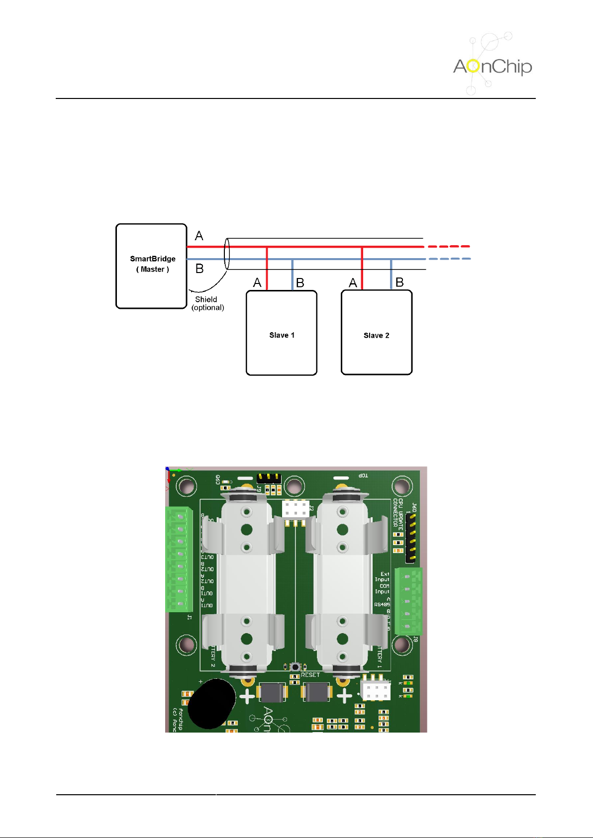
4.1. Electrical diagram .................................................................................................................................. 5
4.2. Connectors ............................................................................................................................................ 5
5. COMMISSIONING......................................................................................................................................... 7
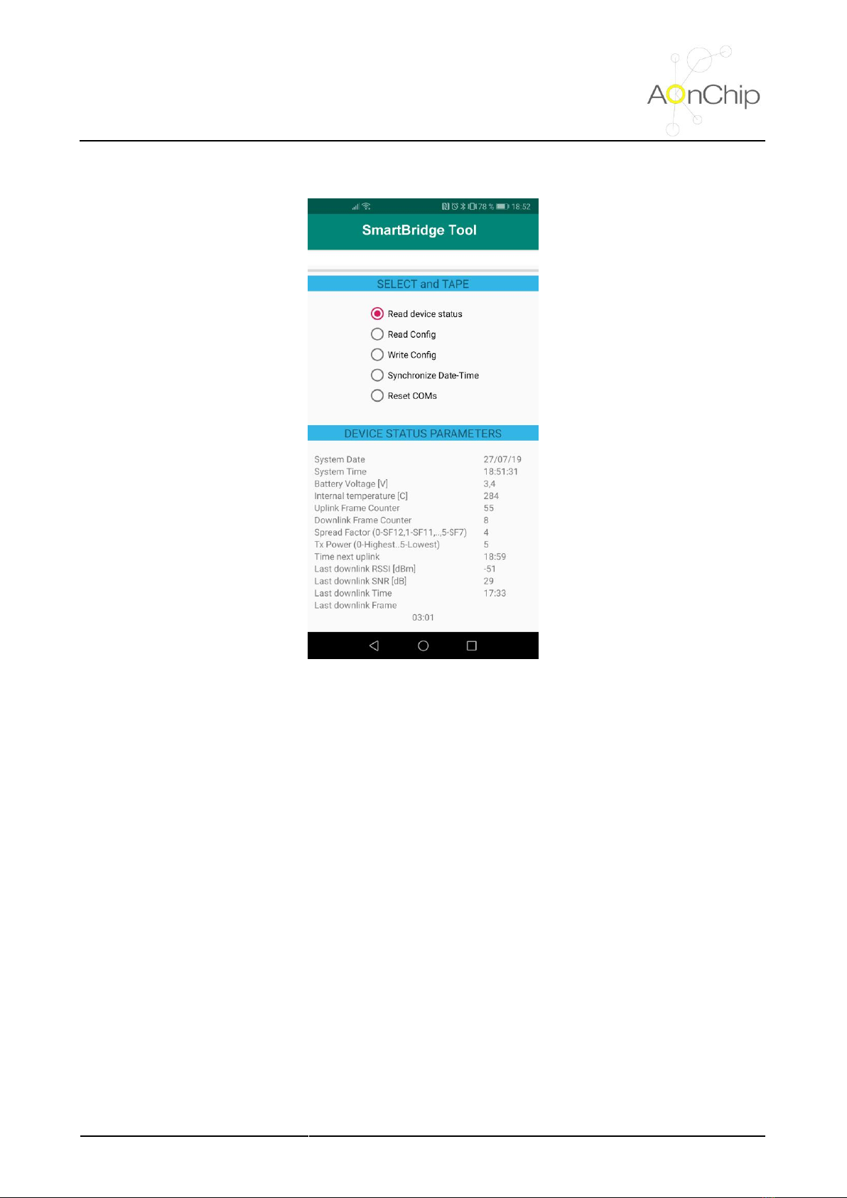
5.1. NFC connectivity ................................................................................................................................... 7
5.2. Setting LoRaWAN communication parameters ..................................................................................... 8
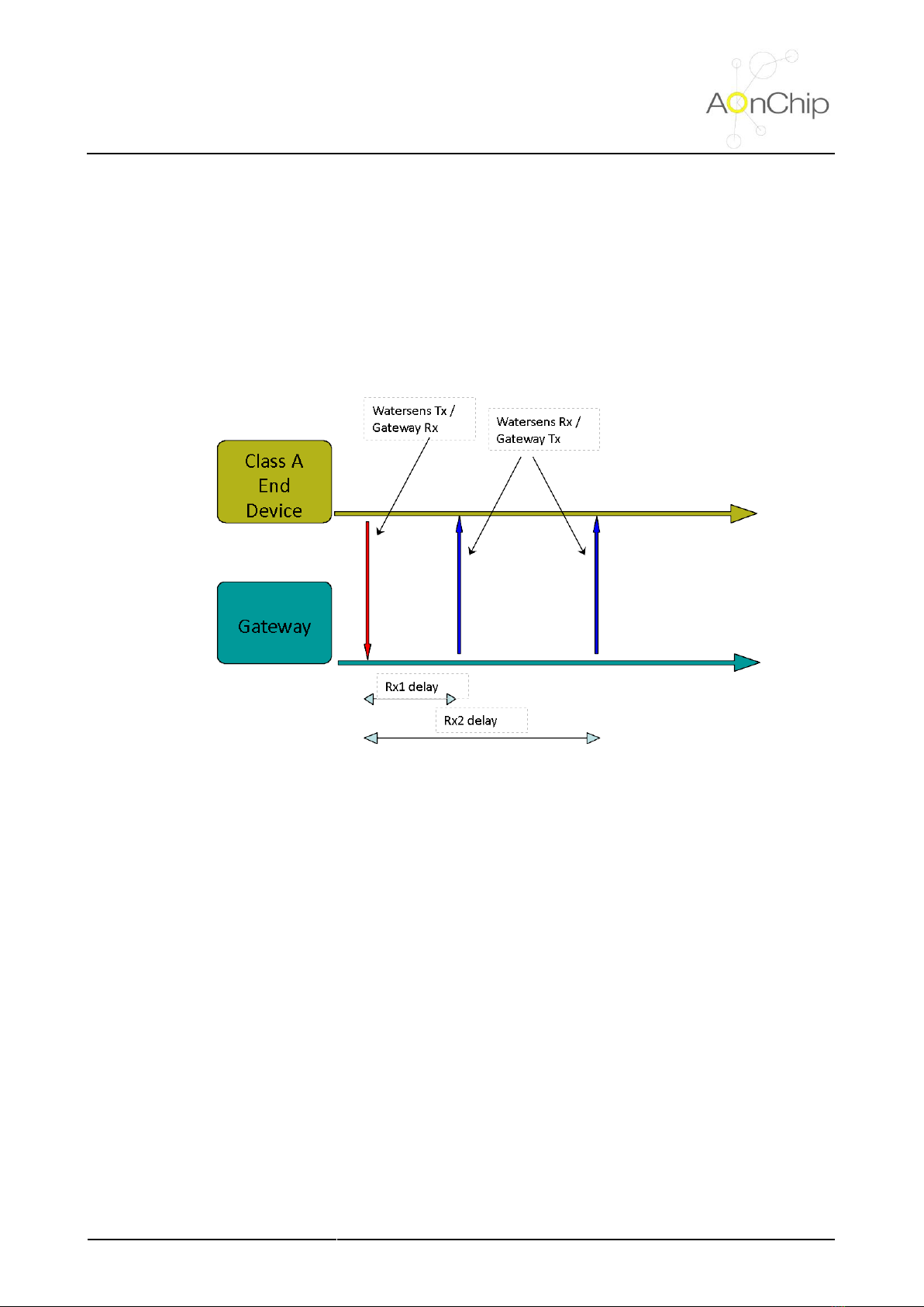
5.2.1. Understanding SmartBridge LoRaWAN profile class....................................................................... 8
5.2.2 LoRaWAN communication parameters ............................................................................................. 8
5.3 Modbus parameters settings .................................................................................................................11
5.3.1 Modbus serial RTU protocol overview..............................................................................................11
5.3.2. Table parameter...............................................................................................................................11
5.4. Checking the setup and establishing first communication .................................................................. 13
6. OPERATION ................................................................................................................................................ 14
6.1. Internal alarm wakeup ......................................................................................................................... 14
6.2. NFC signal detection ........................................................................................................................... 14
6.3. Modbus values request management ................................................................................................. 14
7. DATA FRAME FORMATS............................................................................................................................ 16
7.1. UPLINK FRAMES (FROM NODE TO SERVER) ................................................................................ 16
7.1.1. UPLINK 00 (Reading Modbus parameters) ................................................................................... 16
7.1.2. UPLINK 01 (Reading data type and address of the requested group of Modbus registers) ......... 18
7.1.3. UPLINK 02 (Reading slave address and function of the requested group of Modbus registers) .. 19
7.1.4. UPLINK 03 (Serial Modbus RS485 settings) ................................................................................. 20
7.1.5. UPLINK 04 (SmartBridge status) ................................................................................................... 21
7.2. DOWNLINK FRAMES (FROM SERVER TO NODE).......................................................................... 22
7.2.1. DOWNLINK 01 (Configure Type data and Modbus Address register) ........................................... 22
7.2.2. DOWNLINK 02 (Configure enable parameter, Modbus slave address device and read function) 23
7.2.3. DOWNLINK 03 (Configure Modbus RS485 settings)..................................................................... 24
7.2.4. DOWNLINK 05 (Direct Modbus command to slave) ...................................................................... 25
7.2.5. DOWNLINK 06 (Configure Uplink period) ...................................................................................... 26
7.2.6. DOWNLINK 07 (Configure Time and Date for the SmartBridge) ................................................... 27
7.2.7. DOWNLINK 08 (Next data request for uplink) ............................................................................... 28
8. TROUBLESHOOTING................................................................................................................................. 29
9. MAINTENANCE AND TECHNICAL SERVICE ............................................................................................ 30
9.1. Battery replacement procedure ........................................................................................................... 30
9.2. Firmware update.................................................................................................................................. 30
10. TECHNICAL FEATURES........................................................................................................................... 32
11. PRODUCT REGULATIONS....................................................................................................................... 34
12. TRADEMARKS.......................................................................................................................................... 35
13. GUARANTEE ............................................................................................................................................ 36
14. DOCUMENT HISTORY ............................................................................................................................. 37
15. CONTACT INFORMATION........................................................................................................................ 38

SB020100 - Smart Bridge LoRaWAN - MODBUS
UMAOC003 Rev E
USER MANUAL
Page 2 of 38
2. SAFETY PRECAUTIONS
General considerations:
•Incorrect handling or installation of the unit may result in injury to personnel as well as damage to the
unit or other equipment associated with the system.
•Read the manual carefully prior to connecting the unit. Follow all installation and maintenance
instructions throughout the unit’s working life. Pay special attention to the installation standards of the
National Electrical Code.
•Do not use the device without the cover on.
•Aonchip recommends using the original cables and accessories that are supplied with the device.

SB020100 - Smart Bridge LoRaWAN - MODBUS
UMAOC003 Rev E
USER MANUAL
Page 3 of 38
3. OVERVIEW
Modbus protocol is one of the communication standards more extended in the industrial sector. It is easy to
find many applications with devices which integrate this protocol like energy meters, programmable logic
controllers (PLCs), sensors and so on.
The SmartBridge is a device which works as a Master in the Modbus RS485 network and it is able to read and
write parameters from the Modbus network through the LoRaWAN communication.
Figure 1.SmartBridge external appearance
LoRaWAN is a very extended internet of things (IOT) protocol so it is possible to integrate the SmartBridge in
many platforms to get and manage the data from the device.
Figure 2. Example of integration in a LoRaWAN ecosystem
The SmartBridge is also provided with NFC technology. It means the commissioning process can be carried
out in an easy and safe way through any smartphone with NFC technology and using the app SmartBridge
Tool.

SB020100 - Smart Bridge LoRaWAN - MODBUS
UMAOC003 Rev E
USER MANUAL
Page 4 of 38
Figure 3. Status and configuration parameters can be obtained using the NFC technology in smartphones and SmatrBridge Tool app

SB020100 - Smart Bridge LoRaWAN - MODBUS
UMAOC003 Rev E
USER MANUAL
Page 5 of 38
4. INSTALLATION
4.1. Electrical diagram
Figure 4. Diagram connection for SmartBridge in the RS485 Modbus Network
4.2. Connectors
Figure 5. Connectors location in SmartBridge circuit
J8.1
J8.2
J8.3
J8.4
J8.5

SB020100 - Smart Bridge LoRaWAN - MODBUS
UMAOC003 Rev E
USER MANUAL
Page 6 of 38
Connector
position
Description
Electrical value
J8.1
Not used
J8.2
Not used
J8.3
RS485 communication output – signal A
From -7V to +12V
J8.4
RS485 communication output – signal B
From -7V to +12V
J8.5
Voltage reference for RS485 communication / Shield
0V

SB020100 - Smart Bridge LoRaWAN - MODBUS
UMAOC003 Rev E
USER MANUAL
Page 7 of 38
5. COMMISSIONING
5.1. NFC connectivity
First step is to configure the equipment to register it in the LoRaWAN network and define the Modbus
parameters which must be monitored by the SmartBridge. By default LoRaWAN communication and Modbus
parameters are the values used during manufacturing process to guarantee SmartBridge works correctly for
delivering to final customer.
It is possible to modify the default values via any smartphone with NFC communication. Tapping the cellular
over the front of the housing the values can be read and modified with application SmartBridge Tool.
NOTE 1
NFC communication is very selective. It means the NFC antennas of the smartphone and the SmartBridge
must be aligned. Please check the position of the NFC antenna in smartphone to find the best match position.
The figure below shows the position of the NFC antenna in SmartBridge.
Figure 6. NFC antenna location - white dotted rectangle
NOTE 2
After manufacturing process SmartBridge is programmed in a deep sleep special mode. To wake up the
SmartBridge from this mode only it is possible applying the NFC field (e.g. reading status or configuration via
smartphone with SmartBridge Tool application). If this action is not performed, SmartBridge will remain without
activity.

SB020100 - Smart Bridge LoRaWAN - MODBUS
UMAOC003 Rev E
USER MANUAL
Page 8 of 38
5.2. Setting LoRaWAN communication parameters
5.2.1. Understanding SmartBridge LoRaWAN profile class
SmartBridge can be integrated in a LoRaWAN network as a class A device. It means the device implement a
bi-directional communication profile in which the data sent by server only can be received by the node after
performing an uplink transmission. Is in this moment when the node open two short downlink receive windows
as it is shown in the figure below.
Figure 7. Uplink and downlink communication diagram for A class device
This communication profile is the best option to preserve the battery life as it is the profile which the quantity
of node transmissions is minimal.
5.2.2 LoRaWAN communication parameters
Time to send data
The interval to perform each uplink is defined in minutes. The minimum slot time which can be adjusted is 3
minutes and the maximum is 1400 minutes (once per day).
Must be taken into account as lower is the time to uplink less will be the battery life expected.
Activation method
SmartBridge can be configured in 2 different methods depending on user preferences (security, band
occupancy time, etc)
OTAA (Over The Air Activation Method). SmartBridge receive a device address and an
authorization token from which to derive sessions keys in combination with AppKey parameter
after sending a JOIN request to the server. This method provides high level of security.
ABP (Activation By Personalization). Sessions keys and device network address are predefined.
SmartBridge does not send a JOIN request to server but the security level is lower than OTAA
method.

SB020100 - Smart Bridge LoRaWAN - MODBUS
UMAOC003 Rev E
USER MANUAL
Page 9 of 38
Application EUI (AppEUI)
This parameter is used in OTAA method. It identifies the application during JOIN request. The length is 8 bytes.
Application KEY (AppKey)
This parameter is used in OTAA method. It encrypts data during the JOIN request. The length is 16 bytes.
Device Address (DevAddr)
This parameter is used in ABP method. It is the address in the Lora Network. The length is 4 bytes
Device EUI (DevEUI)
This parameter is used in ABP and OTAA method. The value cannot be modified (predefined in factory) and it
is used to identify the device in Lora Network (it is unique for each device). The length is 8 bytes
Application Session Key (AppSKey)
This parameter is obtained automatically in OTAA mode, but must be defined by user in ABP mode. The
Application Session Key encrypts data during transmission and other applications which can access to the
network cannot see the content of messages. The length is 16 bytes.
Network Session Key (NwkSKey)
This parameter is obtained automatically in OTAA mode, but must be defined by user in ABP mode. The
Network Session Key encrypts data during transmission and other networks cannot see the content of
messages. The length is 16 bytes.
Adaptive Rate
Data rate can be adapted automatically by the network (AUTO) or can be adjusted in a fix value by the user
(OFF).
Data Rate
This parameter is the speed at data which is transferred. It can be adjusted by user if adaptive rate is configured
as OFF.
Depending on the region (EU868, US915, AU915 or AS923) the data rate takes different values.
Table for EU868
DataRate
Configuration
Indicative physical bit rate [bit/s]
0
SF12 / 125kHz
250
1
SF11 / 125kHz
440
2
SF10 / 125kHz
980
3
SF9 / 125kHz
1760
4
SF8 / 125kHz
3125
5
SF7/125kHz
5470
6
SF7 / 250kHz
11000
7
FSK: 50kbps
50000
8..15
RFU

SB020100 - Smart Bridge LoRaWAN - MODBUS
UMAOC003 Rev E
USER MANUAL
Page 10 of 38
Table for US915
DataRate
Configuration
Indicative physical bit rate [bit/s]
0
SF10 / 125kHz
980
1
SF9 / 125kHz
1760
2
SF8 / 125kHz
3125
3
SF7 / 125kHz
5470
5:7
RFU
(visit https://lora-alliance.org/resource-hub/lorawanr-regional-parameters-v102rb for other regions)
Tx Power
The output power can be adjusted according to tables below depending on the region (EU868, US915 or
AS923). Please, take into account the values indicated in tables are maximum limit values, and device could
radiate in equal or lower level.
Table for EU868
TXPower
Configuration (EIRP)
0
Max EIRP (**)
1
Max EIRP - 2dB
2
Max EIRP - 4dB
3
Max EIRP - 6dB
4
Max EIRP - 8dB
5
Max EIRP - 10dB
6
Max EIRP - 12dB
7
Max EIRP - 14dB
8..15
RFU
(*) By default Max EIRP (Equivalent Isotropically Radiated Power) is +14 dBm
Table for US915 ()
TXPower
Configuration (maximum conducted power)
0
30 dBm – 2*TXpower
1
28 dBm
2
26 dBm
3:9
…
10
10 dBm
11:15
RFU
(visit https://lora-alliance.org/resource-hub/lorawanr-regional-parameters-v102rb for other regions)

SB020100 - Smart Bridge LoRaWAN - MODBUS
UMAOC003 Rev E
USER MANUAL
Page 11 of 38
Tx Port
SmartBridge port for data transmission. Values from 1 to 223
Rx Port
SmartBridge port for data reception. Values from 1 to 223
5.3 Modbus parameters settings
5.3.1 Modbus serial RTU protocol overview
Modbus serial RTU is a half-duplex communication protocol which is based on request and answer. The
network is composed by a Master and Slave devices and the Master always initiates the communication. For
each request launched by the Master is followed by an answer from the slave devices. If slaves does not
answer before Timeout(*) is exhausted or slave answers an exception it is considered as an error.
Figure 8. Example of Modbus network over RS485 bus
(*) NOTE The timeout for the SmartBridge is 2s
5.3.2. Table parameter
The SmartBridge can read from the Modbus network up to 20 parameters with 16 or 32 bits length from different
slave devices. Each parameter is defined according to the table below.
Parameter
Data type (*)
Slave address
Modbus function
Register
address
P1
0-Int16 / 1 -Half Float
Nslave (1..254)
03/04
0..65535
P2
0-Int16 / 1 -Half Float
Nslave (1..254)
03/04
0..65535
…
…
…
…
…
P20
0-Int16 / 1 -Half Float
Nslave (1..254)
03/04
0..65535
(*) NOTE
Pay special attention in the setting “Data Type” which is linked with the data format obtained after reading the
Modbus registers:

SB020100 - Smart Bridge LoRaWAN - MODBUS
UMAOC003 Rev E
USER MANUAL
Page 12 of 38
If Data Type is configured as 0 (Integer 16 bits) then the SmartBridge gets the value of the register defined by
“Register address” setting. The value sent in the uplink frame is the same obtained from the slave device.
In case of the Data Type is configured as 1 (Half Float) then the SmartBridge will read a value of 32 bits from
the slave device. It means the SmartBridge will read 16 bits from the register defined in the “Register address”
and the other 16 bits will be obtained from the consecutive “Register address” (Register address + 1).
After getting the 32 bits data (single float 32 bits) it is converted to a 16 bits data (half float) to meet with the
maximum length defined for the uplink frame type 00 (Read value from Modbus parameters).
This setting is useful when it is needed get more than 4 single registers (16 bits), high resolution is not required
and the read parameter will not exceed the value 65504.
The figure below shows how data is adapted from single float (32 bits) to half float (16 bits).
Figure 9. Comparison between Single Float and Half float
Silent interval [ms]
This is the minimum time to consider no activity in the Modbus network and after that is allowed the
communication. This time must be as least 3.5 character according to the Modbus standard. The
values can be configured from 1ms to 1000 ms.
Figure 10. Silence interval between Modbus frames
Baudrate
Rate of the Modbus network data. Values allowed are 1200, 2400, 4800, 9600, 19200,38400, 57600 and
115200

SB020100 - Smart Bridge LoRaWAN - MODBUS
UMAOC003 Rev E
USER MANUAL
Page 13 of 38
Data format
Data length, parity and stop bits defines the format of the Modbus communication data. The values allowed
are shown in the table below.
Format
Data length
Parity
Stop bits
8N1
8 bits
None
1
8N2
8 bits
None
2
8E1
8 bits
Even
1
8O1
8 bits
Odd
1
5.4. Checking the setup and establishing first communication
Once the equipment has been installed and the configuration parameters has been programmed according to
user requirements, SmartBridge is ready to send and to receive data from server.
In most cases the coverage of the network is unknown and it depends on distance and relative height between
node and gateway, the size and the quantity of obstacles in line transmission (as buildings), climatic conditions,
etc. To ensure the success of data transmissions is recommended to initialize the SmartBridge
communications at minimum data rate and maximum transmission power using the mobile application option
“Reset communications”. On other hand configuring “Time slot uplink” at the minimum value (3 minutes) is
also recommended to increase the quantity of transmissions performed by the equipment.
If adaptive data rate is configured as auto (network controls the data rate of the SmartBridge) after several
communications, server and node will adapt the data rate to the value which the occupation of the band and
the power transmission of the node will be lowest. In this case and if it is not necessary, user can modify the
“Time slot uplink” to higher value to save energy from battery.

SB020100 - Smart Bridge LoRaWAN - MODBUS
UMAOC003 Rev E
USER MANUAL
Page 14 of 38
6. OPERATION
SmartBridge is a smart Modbus - LoRaWAN protocol adapter which is powered by batteries. To preserve the
battery life, it is very important to reduce the power consumption when equipment is not carrying out any task,
therefor the SmartBridge enters in sleep mode.
SmartBridge exits from sleep mode if internal alarm wakes up the equipment or if it is detected the NFC signal.
6.1. Internal alarm wakeup
SmartBridge wakes up periodically according to the time defined in “Time Slot uplink” with a random time
deviation from 0s to +10s. This random time is performed by the control unit to avoid possible collisions for
uplinks from other devices units which could send data periodically also.
After waking up SmartBridge carries out several tasks:
•Measures battery voltage
•Measures internal temperature
•Get the data from the Modbus network registers configured by the user
•Check if it is the end of the day (00:00h) to update in EEPROM counters (frame counters and other
internal parameters)
All these tasks take 30 seconds
6.2. NFC signal detection
When NFC field is detected, SmartBridge wakes up and checks if it is received any command from mobile
application. Commands available are:
•Read status parameters
•Read memory configuration (communication and Modbus parameters)
•Write memory configuration (communication and Modbus parameters)
•Time and date synchronization
•Reset communications
•Read Modbus values
When the NFC field disappears SmartBridge enters again in sleep mode.
6.3. Modbus values request management
SmartBridge is able to manage up to 20 registers from a Modbus network. These values are sent in sets of 4
registers with an interval of 3 minutes between sets. After sending the 20 registers a new communication will
be performed once the “Time Slot uplink” has expired.
Finally, if all registers of a set are disabled then the uplink linked with this set will be not sent to avoid not
valuable information.
The figures below show the details of the process.

SB020100 - Smart Bridge LoRaWAN - MODBUS
UMAOC003 Rev E
USER MANUAL
Page 15 of 38
Example 1 – all parameters enabled
Figure 11. Modbus communication management example 1
Example 1 – parameters from 5 to 12 disabled
Figure 12. Modbus communication management example 2

SB020100 - Smart Bridge LoRaWAN - MODBUS
UMAOC003 Rev E
USER MANUAL
Page 16 of 38
7. DATA FRAME FORMATS
7.1. UPLINK FRAMES (FROM NODE TO SERVER)
7.1.1. UPLINK 00 (Reading Modbus parameters)
byte 1
byte 2
byte 3
byte 4
byte 5
byte 6
byte 7
byte 8
byte 9
byte 10
byte 11
tt
de
xg
v1_hi
v1_lo
v2_hi
v2_lo
v3_hi
v3_lo
v4_hi
v4_lo
tt. Type of frame (00 - Reading Modbus parameters)
de. Data type and parameter enabled indicators
(d). Data type indicator (variable type mask - high nibble)
0x1X - Parameter 1 half float data type
0x2X - Parameter 2 half float data type
0x4X - Parameter 3 half float data type
0x8X - Parameter 4 half float data type
0xFX - All parameters are half float data type
(e). Parameter enabled indicator (variable type mask - low nibble)
0xX1 - Parameter 1 enabled
0xX2 - Parameter 2 enabled
0xX4 - Parameter 3 enabled
0xX8 - Parameter 4 enabled
0xXF - All parameters enabled
Examples
Example 1 - 0x45 - (01000101b)
- Parameters 1 and 3 enabled
- Parameter 1 type integer / Parameter 3 type half float
Example 2 - 0x0F - (00001111b)
- All parameters enabled
- All parameters type integer
xg. Parameter read error indicator and index register group
(x). Parameter read error indicator (variable type mask - high nibble)
0x1X - Parameter 1 reading error
0x2X - Parameter 2 reading error
0x4X - Parameter 3 reading error
0x8X - Parameter 4 reading error
0xFX - Reading error in all parameters
Example 1 – 0X - (0000XXXXb) - No error
Example 2 – 8X - (1000XXXXb) - Error reading parameter 4
(g). Index register group (4 bits data - low nibble)
Example – X2 - (XXXX0010b) – Index group register number 2

SB020100 - Smart Bridge LoRaWAN - MODBUS
UMAOC003 Rev E
USER MANUAL
Page 17 of 38
If parameter X was defined as type integer (16 bits) then the value of the parameter can be obtained
in the way:
vX_hi. High part (8 bits) of the value of the parameter X
vX_lo. Low part (8 bits) of the value of the parameter X
Example
- v1_hi - 10d - (00001010b)
- v1_lo - 78d - (01001110b)
- value parameter 1 (16 bits) = v1_hi *256 + v1_lo = 10 * 256 + 78 = 2638
On other hand, if parameter X was defined as type half float (16 bits) then the value of the parameter
can be obtained in the way:
vX_hi. High part (8 bits) of the value of the parameter X
vX_lo. Low part (8 bits) of the value of the parameter X
Example
- v1_hi - 10d - (00001010b)
- v1_lo - 78d - (01001110b)
- value parameter 1 = 0000101001001110
0 -> Bit used to get the sign -> -1^0 -> 1 (+)
00010 -> Bits used to get the exponent -> 2 - 15 = -13
1001001110 -> Bits used to get the mantissa ->
-> 1 + 1 · 2^-1 + 0 · 2^-2 + 0 · 2^-3 + 1 · 2^-4 + 0 · 2^-5 +
+ 0 · 2^-6 + 1 · 2^-7 + 1 · 2^-8 + 1 · 2^-9 + 0 · 2^-10 =
= 1.5625000
value parameter 1 = sign · 2^exponent · mantissa =
= 1 · 2^-13 · 1.5761719 = 0.00019
(*) Please take into account the resolution of the half duplex is lower than the single float. It means
could exist little difference between data in slave address and SmartBridge due to the rounding
process.

SB020100 - Smart Bridge LoRaWAN - MODBUS
UMAOC003 Rev E
USER MANUAL
Page 18 of 38
7.1.2. UPLINK 01 (Reading data type and address of the requested group of Modbus registers)
After receiving the command from the server requesting the addresses of a group of registers SmartBridge will
perform in 3 minutes an uplink with this info. The format of the payload is described below
byte 1
byte 2
byte 3
byte 4
byte 5
byte 6
byte 7
byte 8
byte 9
byte 10
byte 11
tt
dd
gg
a1_hi
a1_lo
a2_hi
a2_lo
a3_hi
a3_lo
a4_hi
a4_lo
tt. Type of frame (01 - Reading address and data type of the Modbus parameters requested)
dd. Parameter type data indicator (variable type mask - low nibble. Values: 0-integer 16 bits /
1-half float 16 bits)
Example 1 - X3 - (XXXX0011b)
- Parameters 1 and 2 defined as half float
- Parameters 3 and 4 defined as integer
Example 2 - X8 - (XXXX1000b)
- Parameters 1, 2 and 3 defined as integer
- Parameters 4 defined as half float
gg. Index register group
Example – 02 - (0000010b) – Index group register number 2
aX_hi. High part (8 bits) of the address of the parameter X
aX_lo. Low part (8 bits) of the address of the parameter X
Example
- a3_hi - 100d - (01100100b)
- a3_lo - 15d - (00001111b)
- address of parameter 3 (16 bits) = a3_hi *256 + a3_lo = 100*256+15 = 25615

SB020100 - Smart Bridge LoRaWAN - MODBUS
UMAOC003 Rev E
USER MANUAL
Page 19 of 38
7.1.3. UPLINK 02 (Reading slave address and function of the requested group of Modbus
registers)
After receiving the command from the server requesting the slave addresses and the Modbus function of a
group of registers SmartBridge will perform in 3 minutes an uplink with this info. The format of the payload is
described below
byte 1
byte 2
byte 3
byte 4
byte 5
byte 6
byte 7
byte 8
byte 9
byte 10
byte 11
tt
ee
gg
slv1
f1
slv2
f2
slv3
f3
slv4
f4
tt. Type of frame (02 - Reading slave address and Modbus function of the Modbus parameters
requested)
ee. Parameter enabled indicator
Example 1 - 03d - (00000011b) - Parameters 1 and 2 enabled
Example 2 - 15d - (00001111b) - All parameters enabled
gg. Index register group
Example – 03 - (0000011b) – Index group register number 3
slvX. Slave address of the device linked with parameter X (8 bits)
Example - slv3 = 01 - Slave Address 01 for parameter 3
fX. Function to read the value of the parameter X (function 03 or 04)
Example - f2 = 04 - Function 04 to read parameter 2
Table of contents