AOpen AK77-333 Datasheet

MIC-In
Line-In
Speaker Out
PS/2 Mouse
Connector
PS/2 Keyboard
Connector
USB Port
(1.1)
SPP/EPP/ECP
Parallel Port
COM 1 Port COM 2 Port
Game Port
Rese
t
able Fuse
A
TX Power Connecto
r
SYSFAN3 Connector
A
GP 4x Expansion Slot
462-pin CPU Socket with Voltage
and Frequency Auto-Detection that
supports AMDTMAthlonTM / DuronTM /
and AthlonTMXP
VIA
®
Apollo KT333 Chipset with
FANsink and VT8233A SB
(ATA100/133 supported)
SYSCPU Fan Connector
with H/W Monitoring
184-pin DIMMx3 supports
DDR333/DDR266 (Max. to
3GB)
IDE Connector x2
(ATA/66/100/133 supported)
FDD Connector
CD-IN Connecto
r
Die Hard BIOS with 100% Virus
Protection (User Upgrade Optional)
JP30 Die Hard BIOS Select Jumpe
r
Onboard AC97 CODEC RealTek ALC650
AUX-IN Connecto
r
CNR Expansion Slo
t
32-bit PCI Expansion Slot x5
(PCI 5 supports slave mode PCI card only)
2nd USB 1.1 Port Connecto
r
Dr. LED Connecto
r
(User Upgrade Optional)
WOM (Wake ON Modem) Connecto
r
WOL (Wake ON LAN) Connecto
r
IrDA Connecto
r
SYSFAN2 Connecto
r
with H/W Monitoring
Front Audio Connecto
r
Front Panel Connecto
r
JP14 CMOS Data Clear Jumpe
r
STB
Y
LED
Chassis Intrusion Sensor Connecto
r
JP21 FSB Select Jumper
3rd and 4th USB 2.0 Port Connecto
r
(Manufacturer Upgrade Optional)
S/PDIF Connecto
r
SW1 CPU Ratio Select Switch

1. JP14 Clear CMOS
Everything you need to boot this
motherboard is included in this
Easy Installation Guide. For more
information, a complete Online
User's Manual can be found in the
Bonus Pack CD Disc. Thanks for
the help of saving our earth.
PART NO: 49.8A101.011(M) DOC. NO:AK77333-EG-E0208C
This Easy Installation Guide x 1
Online Manual x 1
Hard Drive IDE Cable x 1
80-Wire IDE Cable x 1
Floppy Drive Cable x 1
Bonus Pack CD disc x 1
Norton Anti-Virus CD x 1
USB2.0 cable x 1 (User Upgrade Optional)
You can clear CMOS to restore system default setting. To
clear the CMOS, follow the procedure below.
1. Turn off the system and unplug the AC power.
2. Remove ATX power cable from connector PWR2.
3. Locate JP14 and short pins 2-3 for a few seconds.
4. Return JP14 to its normal setting by shorting pin 1 & pin 2.
5. Connect ATX power cable back to connector PWR2.
Tip: When should I Clear CMOS?
1. Boot fail because of overclocking…
2. Forget password…
3. Troubleshooting…
Normal Operation
(default) Clear CMOS
11
Pin 1
2. Die-Hard BIOS (User Upgrade Optional)
Recently, many viruses have been found that they may destroy bios code and data area. Therefore, this
motherboard implements a very effective hardware protection method that does not involve any software
or BIOS coding, hence it is 100% virus free. You may restore the originally mounted BIOS with 2nd BIOS
ROM by setting JP30 to pin 2-3 if it fails to act normally. This motherboard comes with one BIOS ROM, you
may contact our local distributor or reseller for purchasing the extra BIOS ROM. Please visit our website:
english.aopen.com.tw for details.
JP30
Pin 1
BIOS
ROM
Rescue
ROM
Normal Rescue
11

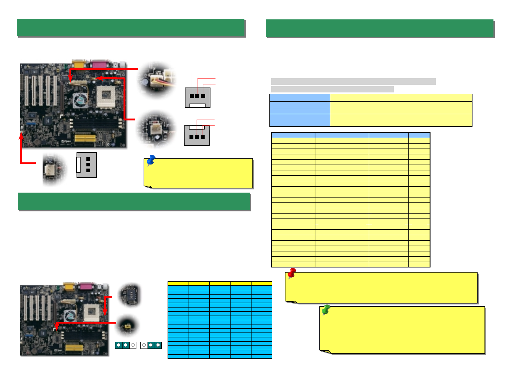
Plug in the CPU fan cable to the 3-pin CPUFAN1 connector. If you have chassis fan, you
can also plug it on SYSFAN2 or SYSFAN3 connector.
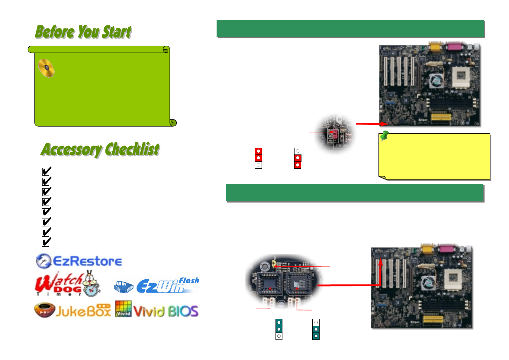
4. JP21 FSB/PCI Clock Ratio
5. Setting CPU Voltage & Frequency
3. Installing CPU & Housing Fan
This jumper is used to specify the relationship of PCI and FSB clock. Generally speaking, i
f
you are not overclockers, we recommend you to set at the default setting. Additionally, this
motherboard also provides “1MHz Stepping Adjustment” feature for overclockers to adjus
t
CPU FSB frequency via BIOS setup program. Based on the CPU type, the adjustment range
has two levels: 100~129 (FSB=100, such as Athlon 800), 130~248 (FSB=133, such as
A
thlon 1000) MHz for your choosing. You may also choose a specific FSB frequency ranging
from 100~117 (say, 105, 110, 115 for example) and 120~156 with reference to a frequenc
y
table in BIOS setup program. If you fix the CPU FSB frequency by JP21, the “1MHz
SteppingAdjustment” range will be changed and following JP21 setting.
Note: Some CPU fans do not have
sensor pin, so that cannot support
fan monitorin
g
.
CPUFAN1 Connector
SYSFAN3 Connector
GND
+12V
Sensor
Setting CPU Core Voltage
This motherboard supports CPU VID function. The CPU core voltage will be automatically
detected and the range is from 1.1V to 1.85V. It is not necessary to set CPU Core Voltage
Setting CPU Frequency
This motherboard is CPU jumper-less design, you can set CPU frequency through the
BIOS setup, and no jumpers or switches are needed.
BIOS Setup > Frequency / Voltage Control > CPU Speed Setup
Core Frequency = CPU FSB Clock * CPU Ratio
CPU Ratio From 5.5x to 12.5x step 0.5x
CPU FSB (By BIOS table) 100, 102, 105, 108, 110, 113, 115, 117, 120, 122, 124, 133, 136, 138,
140, 142, 144, 147, 152, 154, and 156MHz.
CPU FSB (By manual
Adjustment) FSB=100, 100~129 by 1MHz stepping adjustment technology
FSB=133, 130~248 by 1MHz stepping adjustment technology
CPU CPU Core Frequency EV6 Bus Clock Ratio
Athlon 1G 1GHz 200MHz 10.0x
Athlon 1.1G 1.1GHz 200MHz 11.0x
Athlon 1.2G 1.2GHz 200MHz 12.0x
Athlon 1.3G 1.3GHz 200MHz 13.0x
Athlon 1G 1GHz 266MHz 7.5x
Athlon 1.13G 1.13GHz 266MHz 8.5x
Athlon 1.2G 1.2GHz 266MHz 9.0x
Athlon 1.33G 1.33GHz 266MHz 10.0x
Athlon 1.4G 1.4GHz 266MHz 10.5x
AthlonXP 1500+ 1.3GHz 266MHz 10.0x
AthlonXP 1600+ 1.4GHz 266MHz 10.5x
AthlonXP 1700+ 1.46GHz 266MHz 11.0x
AthlonXP 1800+ 1.53GHz 266MHz 11.5x
AthlonXP 1900+ 1.6GHz 266MHz 12.0x
AthlonXP 2000+ 1.667GHz 266MHz 12.5x
AthlonXP 2100+ 1.73GHz 266MHz 13x
AthlonXP 2200+ 1.80GHz 266MHz 13.5x
AthlonXP 2400+ 2.0GHz 266MHz 15x
AthlonXP 2600+ 2.13GHz 266MHz 16x
Duron 800 800MHz 200MHz 8.0x
Duron 850 850MHz 200MHz 8.5x
Duron 900 900MHz 200MHz 9.0x
Duron 950 950MHz 200MHz 9.5x
Duron 1G 1GHz 200MHz 10.0x
Tip: If your system hangs or fails to boot because of
overclocking, simply use <Home> key to restore the default
setting or you can wait the AOpen “Watch Dog Timer” reset
the system in five seconds and system will auto-detect
hardware again.
Warning: VIA®Apollo KT333 chipset supports 133MHz FSB (with
p
erformance reaches ma
x
imum 266MHz EV6 system bus) and 66MHz
A
GP clock, higher clock setting may cause serious system damage.
100MHz 133MHz
(Default)
1 1
GND
+12V
SENSOR
SENSOR
+12V
GND
CPU Ratio SW1-1 SW1-2 SW1-3 SW1-4
5--+-
5.5 +-+-
6-++-
6.5 +++-
7---+
7.5 +--+
8-+-+
8.5 ++-+
9--++
9.5 +-++
10 -+++
10.5 ++++
11 ----
11.5 +---
12 -+--
12.5 ++--
CPUDefault0000
SW1 CPU Ratio
Select Switch
- +
1
2
3
4
SYSFAN2 Connector

1
USB2 Connector
USB3 and USB4 Connector
Pi
n
1
7. Support 2nd, 3rd and 4th USB Ports 9. Connecting Front Panel Cable
This motherboard provides eight USB ports to connect USB devices, such as mouse,
keyboard, modem, printer, etc. There are two connectors on the PC99 back panel. You
can use proper cables to connect the other USB connectors to the USB modules or fron
t
panel of chassis. Please note that USB3 and USB4 support USB2.0. Compared to
traditional USB 1.0/1.1 with the speed of 12Mbps, USB 2.0 (Optional) has a fancy speed
up to 480Mbps, which is 40 times faster than the traditional one.
Speaker
IDE LED
+
+
+
SPWR
+
+ ACPI & PWR
LED
Reset
1
SPWR
GND
ACPI LED-
GND
ACPILED
NC
NC
GND
RESET
GND
NC
NC
+5V
IDE LED
IDE LED
+5V
+5V
GND
NC
SPEAKER
A
ttach the power LED, speaker, and reset switch connector
s
to the corresponding pins. If you enable “Suspend Mode
”
item in BIOS Setup, the ACPI & Power LED will kee
p
flashing while the system is in suspend mode.
Locate the power switch cable from your ATX housing. It is
2-pin female connector from the housing front panel. Plug
this connector to the soft-power switch connector marked
SPWR.
8. Connecting IDE, Floppy Cables
Pin 1 ATA 66/100/133
IDE Connector
FDD Connector
Connect 34-pin floppy cable and 40-pin IDE cable to floppy connector FDC connector. Be
careful of the pin1 orientation. Wrong orientation may cause system damage.
IDE 2 (Secondary)
IDE 1 (Primary)
Pin 1
USBPWR0
USB_FP_P0-
USB_FP_P0+
GND
KEY
USBPWR0
USB_FP_P1-
USB_FP_P1+
GND
USB_FP_OC0
1 2
Pin 1
6. ATX Power Connector
The ATX power supply uses 20-pin connector shown below. Make sure you plug in the
right direction.
+5V
+5V
+5V
+5V
+3.3V
+3.3V
+3.3V
COM
COM COM
COM
COM COM
-5V
COM
-12V
PS-ON
PW-OK
+12V
5VSB

11. Super 5.1 Channel Audio Effect 13. Front Audio Connector
If the housing has been designed with an audio port on the front panel, you’ll be able to
connect onboard audio to front panel through this connector. By the way, please remove 5-6
and 9-10 jumper caps from the Front Audio Connector before connecting the cable. Please
do not remove these 5-6 and 9-10 yellow jumper caps if there’s no audio port on the fron
t
panel.
Pin 1
A
UD_MIC
A
UD_MIC_BIAS
A
UD_FPOUT_
R
NC
A
UD_FROUT_L
AUD_GND
AUD_VCC
AUD_RET_R
KEY
AUD_RET_L
9 10
1 2
This motherboard comes with an ALC650 CODEC, which supports high quality of 5.1
Channel audio effects, bringing you a brand new audio experience. On the strength of the
innovative design of ALC650, you're able to use standard line-jacks for surround audio
output without connecting any external module. To apply this function, you have to install
the audio driver in the Bonus Pack CD as well as an audio application supporting 5.1
Channel. Picture bellow represents the standard location of all speakers in 5.1Channel
sound track. Please connect the plug of your front speakers to the green “Speaker out”
port, rear speakers’ plug to the blue “Line in” port and both of the center and subwoofe
r
speakers to the red “MIC in” port.
10. S/PDIF (Sony/Philips Digital Interface) Connector
S/PDIF (Sony/Philips Digital Interface) is a newest audio transfer file format, which provides
impressive audio quality through optical fiber and allows you to enjoy digital audio instead o
f
analog audio. Through a specific audio cable, you can connect the S/PDIF connector to othe
r
end of the S/PDIF audio module, which bears S/PDIF digital output. Normally there are two
S/PDIF outputs as shown, one for RCA connector, the most common one used for consume
r
audio products, and the other for optical connector with better audio quality. Same as outputs,
you can also connect RCA or optical audio products to input connectors on the module and
have the voice or music come out from your computer. However, you must have a S/PDIF
supported speaker/amplifier/decoder with S/PDIF digital input/output to connect to the S/PDIF
digital input/output to make the most out of this function.
Pin 1
+5VSB
NC
S/PDIFOUT
GND
S/PDIFIN
1
S/PDIF
Cable
S/PDIF IN
(RCA)
(Optical)
S/PDIF OUT
S/PDIF OUT
S/PDIF IN
12. IrDA Connector
The IrDA connector can be configured to support wireless infrared module, with this
module and application software such as Laplink or Windows 95 Direct Cable Connection,
the user can transfer files to or from laptops, notebooks, PDA devices and printers. This
connector supports HPSIR (115.2Kbps, 2 meters) and ASK-IR (56Kbps).
Install the infrared module onto the IrDA connector and enable the infrared function from
BIOS Setup, UART2 Mode, make sure to have the correct orientation when you plug in the
IrDA connector.
NC
+5V
IR_TX
KEY
GND
IR_RX
IrDA Connector
Pin 1

After you finish the setting of jumpers and connect correct cables. Power on
and enter the BIOS Setup, press <Del> during POST (Power On Self Test).
Choose "Load Setup Defaults" for recommended optimal performance.
14. Power-on and Load BIOS Setup
15. AOpen Bonus Pack CD
16. Installing VIA 4in1 Driver
You can use the autorun menu of Bonus CD disc. Choose the utility and driver and selec
t
model name.
Del
Warning: Please avoid of using "Load
Turbo Defaults", unless you are sure
y
our system components (CPU,
SDRAM, HDD, etc.) are good enough for
turbo settin
g
.
You can install the VIA 4 in 1 driver (IDE Bus master (For Windows NT use), VIAATAPI
Vendor Support Driver, VIAAGP, IRQ Routing Driver (For Windows 98 use), VIA Registry
(INF) Driver) from the Bonus Pack CD disc auto-run menu.
Warning: To take advantage of ATA133, it is a must to
install the latest version of VIA 4in1 driver in the Bonus CD.
For Windows2000, it cannot supports ATA133 even after
installing the latest version of VIA 4-in-1 driver until the new
release of Service-Pack 3 from Microsoft.
17. BIOS Upgrade under Windows Environment
You may accomplish BIOS upgrade procedure with EzWinFlash by the following steps,
and it’s STRONGLY RECOMMMANDED to close all the applications before you start the
upgrading.
1. Download the new version of BIOS package zip file from AOpen official web site. (ex:
http://english.aopen.com.tw/)
2. Unzip the download BIOS package (ex: WAK77333102.ZIP) with WinZip
(http://www.winzip.com) in Windows environment.
3. Save the unzipped files into a folder, for example, WAK77333102.EXE &
WAK77333102.BIN.
4. Double click on the WAK77333102.EXE, EzWinFlash will detect the model name and
BIOS version of your motherboard. If you had got the wrong BIOS, you will not be
allowed to proceed with the flash steps.
5. You may select preferred language in the main menu, then click [Start Flash] to star
t
the BIOS upgrade procedure.
6. EzWinFlash will complete all the process automatically, and a dialogue box will pop
up to ask you to restart Windows. You may click [YES] to reboot Windows.
7. Press <Del> at POST to enter BIOS setup, choose "Load Setup Defaults", then
“Save & Exit Setup”. Done!
Warning: The upgrade of new BIOS will permanently replace your original BIOS
content after flashing. The original BIOS setting and Win95/Win98 PnP
information will be refreshed and you probably need to re-configure your system.

If you encounter any trouble to boot you system, follow the procedures
accordingly to resolve the problem.
Part Number and Serial Number
The Part Number and Serial number are printed on bar code label. You can find this
bar code label on the outside packing, or on component side of PCB. For example:
Model name and BIOS version
AK77-333 R1.00 May. 01. 2002AOpen Inc.
Award Plug and Play BIOS Extension v1.0A
Copyright © 1998,Award Software, Inc.
Model name and BIOS version can be found on upper left corner of first boot screen
(POST screen). For example:
AK77-333 is model name of motherboard; R1.00 is BIOS version
Make sure if the jumper settings for CPU and DRAMs are correct.
Clear CMOS.
Install the VGA card. Then connect your monitor and keyboard.
The problem was probably caused
by power supply or motherboard
failure. Please contact your reselle
r
or local distributor for repairing.
Perhaps your VGA card or monito
r
is defective.
No
Yes
No
Yes
It is very possible that your keyboard
is defective.
During system rebooting, press Del to enter BIOS Setup. Choose
“Load Setup Default".
The problem should be caused by the
IDE cables or HDD itself.
Re-install Windows 95, Windows 98 or Windows NT.
Yes
Yes
Turn off the power and unplug the AC power cable, then remove all
of the addon cards and cables, including VGA, IDE, FDD, COM1,
COM2 and Printer.
Turn on the power, and check if
the power supply and CPU fan
work properly.
Start
Check if there is display.
Press Ctrl, and Alt key at the
same time, hold them and then
press Del to see if the
s
y
stem reboots.
Turn off the system and
re-connect the IDE cable.
Check if the system can
reboot successfully.
End
No
No
P/N: 91.88110.201 is part number, S/N: 91949378KN73 is serial number.
Part No. Serial No.
Part No. Serial No.

Dear Customer,
Thanks for choosing AOpen products. To provide the best and fastest service to
our customer is our first priority. However, we receive numerous emails and
p
hone-calls worldwide everyday, it is very hard for us to serve everyone on time.
We recommend you follow the procedures below and seek help before contact
us. With your help, we can then continue to provide the best quality service to
more customers.
Thanks very much for your understanding!
A
Open Technical Supporting Team
Pacific Rim
AOpen Inc.
Tel: 886-2-3789-5888
Fax: 886-2-3789-5899
America
AOpen America Inc.
Tel: 1-510-489-8928
Fax: 1-510-489-1998
Europe
AOpen Computer b.v.
Tel: 31-73-645-9516
Fax: 31-73-645-9604
Germany
AOpen Computer GmbH.
Tel: 49-1805-559191
Fax: 49-2102-157799
China
艾爾鵬國際貿易(上海)有限公
司
Tel: 86-21-6225-8622
Fax: 86-21-6225-7926
Japan
AOpen Japan Inc.
Tel: 81-048-290-1800
Fax: 81-048-290-1820
Web Site: www.aopen.com
E-mail: Send us email by going through the contact form below.
English http://english.aopen.com.tw/tech/default.htm
Japanese http://www.aopen.co.jp/tech/default.htm
Chinese http://www.aopen.com.tw/tech/default.htm
German http://www.aopencom.de/tech/default.htm
Simplified Chinese http://www.aopen.com.cn/tech/default.htm
Online Manual: Please check the manual carefully and make sure the
jumper settings and installation procedure are correct.
http://english.aopen.com.tw/tech/download/manual/default.htm
1
1
Test Report: We recommend choosing board/card/device from the
compatibility test reports for assembling your PC.
http://english.aopen.com.tw/tech/report/default.htm
2
2
FAQ: The latest FAQ (Frequently Asked Questions) may contain a
solution to your problem.
http://english.aopen.com.tw/tech/faq/default.htm
5
5
Download Software: Check out this table to get the latest updated
BIOS/utility and drivers.
http://english.aopen.com.tw/tech/download/default.htm
3
3
News Group: News posted by computer experts, you are welcome to join
any discussion and learning from it.
http://english.aopen.com.tw/tech/newsgrp/default.htm
4
4
Contact Distributors/Resellers: We sell our products through resellers
and integrators. They should know your system configuration very well and
should be able to solve your problem efficiently and provide important
reference for you if next time you want to buy something else from them.
6
6
Contact Us: Please prepare detail system configuration and error symptom
before contacting us. The part number, serial number and BIOS version
are also very helpful.
7
7
Other manuals for AK77-333
1
Table of contents
Other AOpen Motherboard manuals

AOpen
AOpen MX3S-U Setup guide

AOpen
AOpen i915Ga-HFS User manual

AOpen
AOpen MX3W-E2 Setup guide

AOpen
AOpen i945GTm-VHL User manual

AOpen
AOpen AX45H-8X Max Setup guide

AOpen
AOpen i945GTm-VHL Datasheet

AOpen
AOpen DXPN-U Datasheet

AOpen
AOpen AX33 Setup guide

AOpen
AOpen AK77 PRO Datasheet

AOpen
AOpen Fortress 9500 User manual