AOpen AK77-600GN Datasheet

SYSFAN2 Connector
IrDA Connector
Front Panel Connector
FDD
C
onnecto
r
USB 2.0 Connecto
r
sx2
JP14 CMOS Clear Jumper
2Mb Flash ROM BIOS
Resetable Fuse
462-pin CPU Socket with Voltage and
Frequency Auto-Detection that supports
AMDTMAthlonTM / DuronTM / and AthlonTMXP
(with CPU Overheat Protection circuit to
AthlonTMXP CPU onl
y)
CPUFAN Connecto
r
184-pin DIMMsx3 supports
DDR 266/333/400 (Max to 3GB)
VIA
®
Apollo KT600 / VT8237 Chipsets
3300μF Low ESR Capacitors
ATX Power Connector
CD-IN Connector
Onboard AC’97 CODEC
Case Open Connector
Front Audio Connector
JP28 Keyboard/Mouse Wakeup Jumpe
r
SYSFAN1 Connector
Realtek LAN Chip
8X AGP slot
AUX-IN Connector
GAME Port Connector
W
a
k
e
O
n
LAN
C
onnecto
r
ATA 66/100/133 IDE Connectors x2
STBY LED
AOpen reserves the right to revise all the specifications and information contained in this documentation, which are subject to change without notice.
32-bit PCI Expansion Slots x5
Line-In
Speaker Out
MIC-In
PS/2 Mouse
Connecto
r
SPP/EPP/ECP Parallel Port RJ45 LAN Jack
PS/2 Keyboard
Connecto
r
USB Ports
COM 1 Port COM 2 Port
USB Ports
JP21 K7 Host Clock Select Jum
p
e
r
SATA
C
onnectorsx
2
S/PDIF Connector

1. JP14 Clear CMOS
Everything you need to boot this
motherboard is included in this
Easy Installation Guide. For more
information, a complete Online
User's Manual can be found in the
Bonus Pack CD Disc. Thanks for
the help of saving our earth.
PART NO: 49.8A706.EE4 DOC. NO: AK77600GN-EG-E0312D
You can clear CMOS to restore system default setting. To
clear the CMOS, follow the procedure below.
1. Turn off the system and unplug the AC power.
2. Remove ATX power cable from connector PWR2.
3. Locate JP14 and short pins 2-3 for a few seconds.
4. Return JP14 to its normal setting by shorting pin 1 & pin 2.
5. Connect ATX power cable back to connector PWR2.
Tip: When should I Clear CMOS?
1. Boot fails because of overclocking…
2. Forget password…
3. Troubleshooting…
Motherboard x1
Easy Installation Guide x1
80-wire IDE Cable x1
Floppy Disk Drive Cable x1
SerialATACablex1
IO Shield x 1
Bonus Pack CD x1
VIA SATA RAID Driver Diskette x 1
Pin 1
2. JP28 Keyboard/Mouse Wake-up Enable/Disable Jumper
This motherboard provides keyboard / mouse wake-up function. You can use JP28 to enable or disable this
function, which could resume your system from suspend mode with keyboard or mouse installed. The factory
default setting is set to “Disable” (1-2), and you may enable this function by setting the jumper to 2-3.
JP28
KB/Mouse Wake-up
Pin 1
Normal
(
default
)
11
Clear CMOS
Enable
Disable
(Default)
11

Plug in the CPU fan cable to the 3-pin CPUFAN connector. If you have chassis fan, you
can also plug it on SYSFAN1 or SYSFAN2 connector.
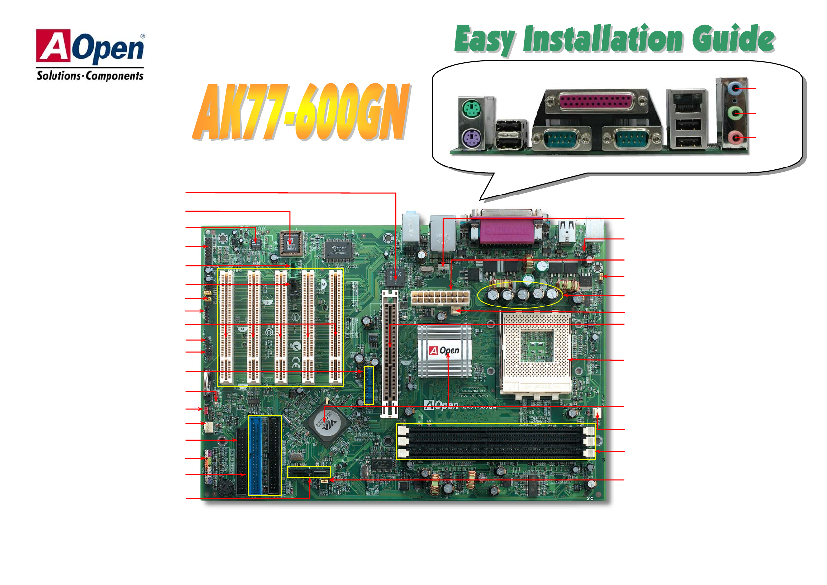
The ATX power supply uses a 20-pin connector shown below. Make sure you plug in the
right direction.
CPU Ratio From 5.0x to 18x step 0.5x
CPU FSB 100-248MHz
CPU CPU Core
Frequency
EV6 Bus
Clock Ratio
Athlon 1.33G 1.33GHz 266MHz 10.0x
Athlon 1.4G 1.4GHz 266MHz 10.5x
AthlonXP 1500+ 1.3GHz 266MHz 10.0x
AthlonXP 1600+ 1.4GHz 266MHz 10.5x
AthlonXP 1700+ 1.46GHz 266MHz 11.0x
AthlonXP 1800+ 1.53GHz 266MHz 11.5x
AthlonXP 1900+ 1.6GHz 266MHz 12.0x
AthlonXP 2000+ 1.667GHz 266MHz 12.5x
AthlonXP 2100+ 1.73GHz 266MHz 13x
AthlonXP 2200+ 1.80GHz 266MHz 13.5x
AthlonXP 2400+ 2.0GHz 266MHz 15x
AthlonXP2500+ (Barton) 1.833GHz 333MHz 11x
AthlonXP 2600+ 2.13GHz 266MHz 16x
AthlonXP 2600+ 2.08GHz 333MHz 12.5x
AthlonXP 2700+ 2.16GHz 333MHz 13x
AthlonXP 2600+ (Barton) 1.917GHz 333MHz 11.5x
AthlonXP 2800+ (Barton) 2.083GHz 333MHz 12.5x
AthlonXP 3000+ (Barton) 2.167GHz 333MHz 13x
AthlonXP 3000+ (Barton) 2.100GHz 400MHz 10.5x
AthlonXP 3200+ (Barton) 2.2GHz 400MHz 11x
Note: With CPU speed changing rapidly, there might be fastest CPU on the
market by the time you received this installation guide. This table is kindly for
your references only.
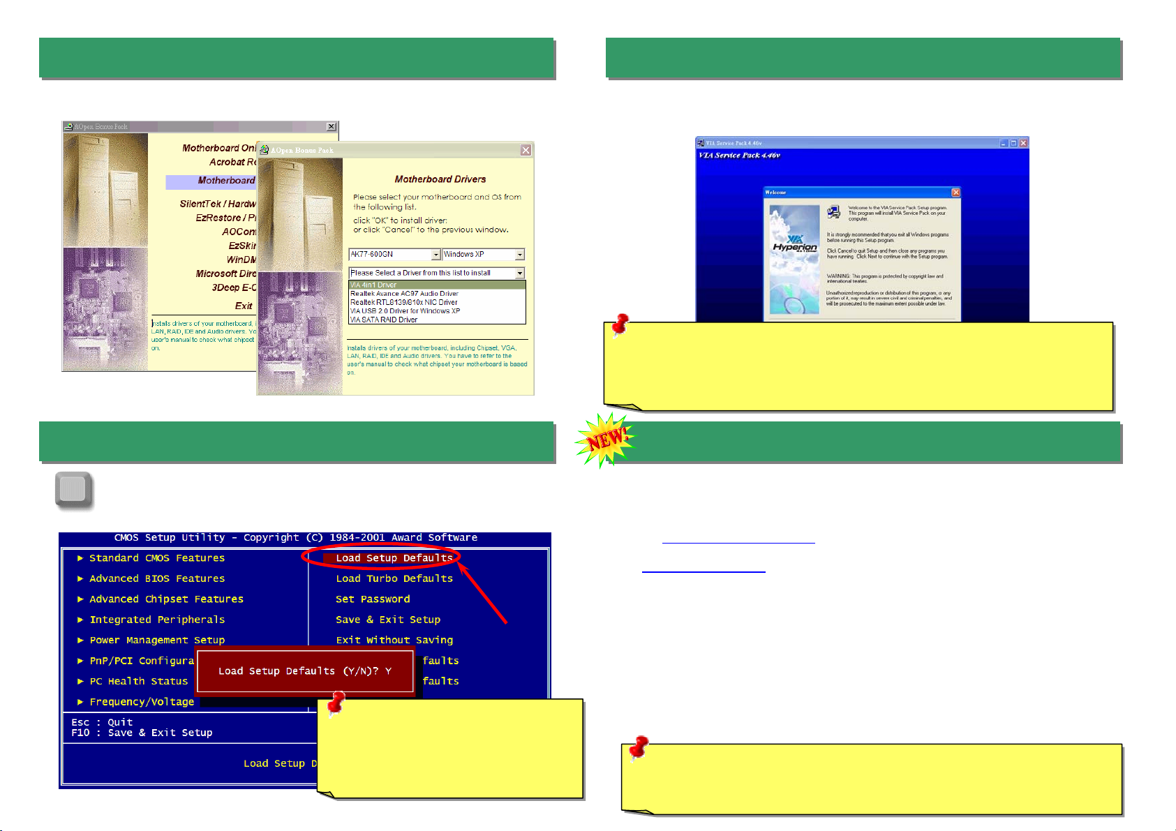
5. Setting CPU Voltage & Frequency
CPU Core Voltage Auto Detectable
This motherboard supports CPU VID function. The CPU core voltage will be automatically
detected and it is not necessary to set CPU Core Voltage.
Setting CPU Frequency
This motherboard is CPU jumper-less design, you can set CPU frequency through the BIOS
setup, and no jumpers or switches are needed.
BIOS Setup > Frequency / Voltage Control > CPU Bus Frequency
Core Frequency = CPU FSB Clock * CPU Ratio
Warning: Supposed you
have had adjusted CPU
ratio on your current CPU,
and you plan to replace it
with a new CPU. Please
use <Home> key or Clear
CMOS to restore the
default setting after
reinstalling a new CPU.
Note: Some CPU fans do not have
sensor pin so they cannot support fan
monitoring.
CPUFAN Connector
4. Installing CPU & System Fan
SYSFAN1 Connector
SYSFAN2 Connector
GND
+12V
SENSOR
3. Connecting ATX Power Connector
GND
+12V
SENSOR
GND
+12V
SENSOR
Note:VIA®Apollo KT600 chipset supports 266/333/400MHz FSB with
performance reaches maximum 400MHz EV6 system bus and supports 66MHz
AGP clock, higher clock setting may cause serious system damage.
Tip: If your system hangs
or fails to boot because of
overclocking, simply use
<Home> key to restore the
default setting or you can
wait till the AOpen “Watch
Dog ABS” reset the system
in five seconds and system
will auto-detect hardware
again.

8. S/PDIF Connector
S/PDIF (Sony/Philips Digital Interface) is a newest audio transfer file format, which provides
impressive audio quality through optical fiber and allows you to enjoy digital audio instead of analog
audio. Through a specific audio cable, you can connect the S/PDIF connector to other end of the
S/PDIF audio module, which bears S/PDIF digital output. Normally there are two S/PDIF outputs as
shown, one for RCA connector, the most common one used for consumer audio products, and the
other for optical connector with better audio quality. Same as outputs, you can also connect RCA or
optical audio products to input connectors on the module and have the voice or music come out from
your computer. However, you must have a S/PDIF supported speaker/amplifier/decoder with S/PDIF
digital input/output to connect to the S/PDIF digital input/output to make the most out of this function.
This motherboard comes with an ALC650F CODEC, which supports high quality of 5.1
Channel audio effects, bringing you a brand new audio experience. On the strength of the
innovative design of ALC650F, you're able to use standard line-jacks for surround audio
output without connecting any external module. To apply this function, you have to install the
audio driver in the Bonus Pack CD as well as an audio application supporting 5.1 Channel.
Picture bellow represents the standard location of all speakers in 5.1Channel sound track.
Please connect the plug of your front speakers to the green “Speaker out” port, rear
speakers’ plug to the blue “Line in” port and both of the center and subwoofer speakers to
the red “MIC in” port.
USB 2.0 Connector
Pi
n
1
9. Super 5.1 Channel Audio Effects
6. JP21 K7 Host Clock Selection
7. Support Eight USB 2.0 Ports
+5V
SBD7-
SBD7+
GND
NC
+5V
SBD6-
SBD6+
GND
KEY
USB 2.0 Connector
1
This jumper is used to specify the relationship of PCI and FSB clock. Generally speaking, if
you are not an over-clocker, we recommend you to set it to the default setting. Additionally,
this motherboard also provides “1MHz Stepping Adjustment” feature for overclockers to
adjust CPU FSB frequency via BIOS setup program. If you fix the CPU FSB frequency by
JP21, the “1MHz Stepping Adjustment” range will be changed according to what type of
CPU you use.
JP21 K7 Host Clock
Select Jum
p
e
r
This motherboard provides eight USB 2.0 ports. Compared to traditional USB 1.0
/
1.1 with
the speed of 12Mbps, USB 2.0 has a fancy speed up to 480Mbps, which is 40 times faster
than the traditional one.
Pi
n
1
Pin 1
100MHz
Auto detect
(
default
)
11
S/PDIF Module
(User Upgrade Optional)
S/PDIF
Cable
S/PDIF OUT
S/PDIF IN
(RCA)
S/PDIF IN
(
O
p
tical
)
S/PDIF OUT
5
1+5V
NC
SPDIFOUT
GND
SPDIFIN
Pin 1

10. Connecting Front Panel Cable
Attach the power LED, speaker, and reset switch connectors to
the corresponding pins. If you enable “Suspend Mode” item in
BIOS Setup, the ACPI & Power LED will keep flashing while the
system is in suspend mode.
Locate the power switch cable from your ATX housing. It is
2-pin female connector from the housing front panel. Plug this
connector to the soft-power switch connector marked SPWR.
11. Connecting Serial ATA Disk
12. Front Audio Connector
13. Support 10/100 Mbps LAN onboard
On the strength of Realtek 8101L LAN controller on board, this motherboard provides
10/100 Mbps Ethernet for office and home use. The Ethernet RJ45 connector is located
on top of USB connectors. The orange LED indicates the link mode, it lights when linking
to network. The green LED indicates the transfer mode and it lights when data is
transferring in 100 Mbps. To enable or disable this function, you may simply adjust it
through BIOS.
If the housing has been designed with an audio port on the front panel, you’ll be able to
connect onboard audio to front panel through this connector. By the way, please remove
5-6 and 9-10 jumper caps from the Front Audio Connector before connecting the cable.
Please do not remove these 5-6 and 9-10 yellow jumper caps if there’s no audio port on
the front panel.
Pin 1
1
AUD_GND
AUD_VCC
AUD_RET_R
KEY
AUD_RET_L
AUD_MIC
AUD_MIC_BIAS
AUD_FPOUT_R
NC
AUD_FPOUT_L
Front Audio Connector
To connect a Serial ATA disk, you have to have a 7-pin serial ATA cable. Connect two ends
of the serial ATA cable to the serial ATA header on the motherboard and the disk. Like
every other traditional disk, you also have to connect a power cable. Please be noted that
it is a jumper free implement; you don’t need to set jumpers to define a master or slave
disk. When connecting two serial ATA disks, the system will automatically take the one
connected to “Serial ATA 1” header as a master disk.
Orange/Link
Green/Transfer
1
SPEAKER
IDE LED
Power Switch
ACPI & Power LED
RESET
SPWR
GND
ACPILED-
GND
ACPILED+
NC
NC
GND
RESET
GND
NC
NC
+5V
IDE LED
IDE LED
+5V
+5V
GND
NC
SPEAKER
1
SATA port 2SATA port 1
Other manuals for AK77-600GN
1
Table of contents
Other AOpen Motherboard manuals

AOpen
AOpen MX3S Datasheet

AOpen
AOpen i855GMEm-LFS User manual

AOpen
AOpen S661FXM-US User manual

AOpen
AOpen AX4C Max II Setup guide

AOpen
AOpen AX6LC User manual

AOpen
AOpen AX4SP-G Setup guide

AOpen
AOpen MX4SG-4DL Datasheet

AOpen
AOpen MX34-U Setup guide

AOpen
AOpen AX63PRO Setup guide

AOpen
AOpen AK77-400 Setup guide

AOpen
AOpen AX4SG Max II User manual

AOpen
AOpen AK76F-400N Setup guide

AOpen
AOpen AK73-1394 Setup guide

AOpen
AOpen MX46U2-GN Setup guide

AOpen
AOpen MX46U2-VN Setup guide

AOpen
AOpen MX4BS Setup guide

AOpen
AOpen MX46-800N Datasheet

AOpen
AOpen AX59PRO User manual

AOpen
AOpen s760GXm-US User manual

AOpen
AOpen AP53 User manual