AOpen AX4B-533 Tube Datasheet

PS/2 Mouse
Connector SPP/EPP/ECP Parallel Port MIDI/Game Port
MIC-In
Line-In
Speaker Out
PS/2 Keyboard
Connector USB2.0 Port
COM 1 Port COM 2 Port
FAN3 Connecto
r
JP15 & 16 Dr. Voice II Languages
Select Jumper
(Volume adjustable through speaker)
CD-IN Connecto
r
IrDA Connecto
r
Front Panel Connecto
r
FDD Connecto
r
2nd and 3rd USB2.0 Connecto
r
JP14 CMOS Clear Jumpe
r
4Mbit Flash ROM
Resetable Fuse
478-pin CPU socket with Voltage and
Frequency Auto-detection that supports
Intel®Pentium®4 1.4~2.4GHz+ CPU
A
GP 4x Expansion Slot
(for 1.5V AGP card)
32-bit PCI Expansion Slot x3
CPU Fan Connector with H/W
Monitoring Function
184-pin DIMM Socket x3 supports
PC-200/266 DDR SDRAM
maximum up to 2 GB
Intel
®
845E chipset (Brookdale)
With 400/533 FSB
2200μF Low ESR Capacitors
ATX Power Connector
AUX-IN Connecto
r
4-pin 12V. ATX Power Connector
Onboard AC’97 CODEC
Chassis Intrusion Sensor Connecto
r
Front Audio Connecto
r
WOL Connecto
r
WOM Connecto
r
JP28 Keyboard/Mouse Wakeup
Enable/Disable Jumper
ATA/33/66/100 IDE Connector x2
FAN2 Connector
JP1 (Buzzer) & JP2 (speaker)
RJ45 LAN Port
JP3 Tube Power Jumpe
r
Tube
A
udio Connecto
r
(Line-in and RCA/Headphone/S/PDIF)
MultiCap Hi-End Audio Grade Capacito
r
Sovtek 6922 Dual Triode Tube
& Tube Base
Maxim 668 DC-DC Converte
r
Vishay Resisto
r
BOOT LED
STBY LED
A
GP LED

This motherboard provides keyboard / mouse wake-up function. You can use JP28 to enable or disable this
function, which could resume your system from suspend mode with keyboard or mouse installed. The factor
y
default setting is set to “Disable”(1-2), and you may enable this function by setting the jumper to 2-3.
1. JP14 Clear CMOS
Everything you need to boot this
motherboard is included in this
Easy Installation Guide. For more
information, a complete Online
User's Manual can be found in the
Bonus Pack CD Disc. Thanks for
the help of saving our earth.
PART NO: 49.8A210.E01 DOC. NO: AX4B533Tube-EG-E0206A
You can clear CMOS to restore system default setting. To
clear the CMOS, follow the procedure below.
1. Turn off the system and unplug the AC power.
2. Remove ATX power cable from connector PWR2.
3. Locate JP14 and short pins 2-3 for a few seconds.
4. Return JP14 to its normal setting by shorting pin 1 & pin 2.
5. Connect ATX power cable back to connector PWR2.
Tip: When should I Clear CMOS?
1. Boot fail because of overclocking…
2. Forget password…
3. Troubleshooting…
2. JP28 Keyboard/Mouse Wakeup Enable/Disable Jumper
This Motherboard x1
This Easy Installation Guide x1
User Manual x 1
40-wire IDE Cable x1
80-wire IDE Cable x1
Floppy Disk Drive Cable x1
Retention Module x1
Bonus Pack CD x1
Sovtek 6922 dual Triode tube x1
Cardas hyper copper wire x1 (User Upgrade Optional)
Tube Audio Card x1 (User Upgrade Optional)
Pin 1
Normal Operation
(default) Clear CMOS
1 1
Enable
Disable
(Default)
Pin 1

Plug in the CPU fan cable to the 3-pin CPU FAN connector. If you have chassis fan, you
can also plug it on System Fan (FAN2) or FAN3 (AUX Fan) connector.
CPU Ratio 8x, 9x, 10x… 21x, 22x, 23x, 24x
CPU FSB 100~248MHz
Northwood CPU CPU Core
Frequenc FSB Clock System Bus Ratio
Pentium 4 1.6G 1600MHz 100MHz 400MHz 16x
Pentium 4 1.8G 1800MHz 100MHz 400MHz 18x
Pentium 4 2.0G 2000MHz 100MHz 400MHz 20x
Pentium 4 2.2G 2200MHz 100MHz 400MHz 22x
Pentium 4 2.4G 2400MHz 100MHz 400MHz 24x
Willamette CPU CPU Core
Frequenc FSB Clock System Bus Ratio
Pentium 4 1.5G 1500MHz 100MHz 400MHz 15x
Pentium 4 1.6G 1600MHz 100MHz 400MHz 16x
Pentium 4 1.7G 1700MHz 100MHz 400MHz 17x
Pentium 4 1.8G 1800MHz 100MHz 400MHz 18x
Pentium 4 1.9G 1900MHz 100MHz 400MHz 19x
Pentium 4 2.0G 2000MHz 100MHz 400MHz 20x
5. Setting CPU Voltage & Frequency
Setting CPU Core Voltage
This motherboard supports CPU VID function. The CPU core voltage will be automatically
detected and the range is from 1.10V to 1.85V. It is not necessary to set CPU core voltage.
Setting CPU Frequency
This motherboard is CPU jumper-less design, you can set CPU frequency through the
BIOS setup, and no jumpers or switches are needed.
BIOS Setup > Frequency / Voltage Control > CPU Speed Setting
Core Frequency = CPU FSB Clock * CPU Ratio
Note: Some CPU fans do not have
sensor pin so they cannot support fan
monitoring.
CPU Fan Connector
Warning: Intel®845E chipset supports maximum 400/533MHz
(100/133MHz*4) system bus and 66MHz AGP clock; higher clock
setting may cause serious system damage.
3. Installing CPU & System Fan
FAN3 Connector
GND
+12V
SENSOR
FAN2 Connector
GND
+12V
SENSOR
4. Connecting Front Panel Cable
Attach the power LED, speaker, and reset switch connectors to
the corresponding pins. If you enable “Suspend Mode” item in
BIOS Setup, the ACPI & Power LED will keep flashing while the
system is in suspend mode.
Locate the power switch cable from your ATX housing. It is
2-pin female connector from the housing front panel. Plug this
connector to the soft-power switch connector marked SPWR.
A
CPI & PWR
LED
1
Speaker
IDE LED
SPWR
Reset
1
5VSB
SPWR
ACPI LED-
GND
ACPILED
NC
NC
GND
RESET
GND
NC
NC
+5V
IDE LED
IDE LED
+5V
+5V
GND
NC
SPEAKER
Note: Since the latest processor, Northwood, would detect the
clock ratio automatically, you may not be able to adjust the clock
ratio in BIOS manually.
Pin 1

Secondary
Master (3rd)
Secondary
Slave (4th)
Pin 1
Primary
Slave (2nd) Primary
Master (1st)
USBPWR0
USB_FP_P0-
USB_FP_P0+
GND
KEY
USBPWR0
USB_FP_P1-
USB_FP_P1+
GND
USB_FP_OC0
1 2
8. Connecting IDE and Floppy Cables
Connect 34-pin floppy cable and 40-pin, 80-wire IDE cable to floppy connector FDC and
IDE connector. Be careful of the pin1 orientation. Wrong orientation may cause system
damage.
Pin 1
ATA 33/66/100
IDE Connector FDD Connector
IDE 1 (Primary)
IDE 2 (Secondary)
9. Support Six USB2.0 Connectors
Compared to traditional USB 1.0/1.1 with the speed of 12Mbps, USB 2.0 has a fancy
speed up to 480Mbps, which is 40 times faster than the traditional one. Except for the
speed increase, USB 2.0 supports old USB 1.0/1.1 software and peripherals, offering
impressive and even better compatibility to customers. On this motherboard, all USB
connectors support USB 2.0 function. To connect those two headers, you have to use
proper USB cables and connect them to any USB models.
USB2 Connector
Pin 1
7. Front Audio Connector
If the housing has been designed with an audio port on the front panel, you’ll be able to
connect onboard audio to front panel through this connector. By the way, please remove
5-6 and 9-10 jumper caps from the Front Audio Connector before connecting the cable.
Please do not remove these 5-6 and 9-10 yellow jumper caps if there’s no audio port on
the front panel.
Pin 1
A
UD_MIC
NC
A
UD_FPOUT_
R
NC
A
UD_FROUT_L
AUD_GND
AUD_VCC
AUD_RET_R
KEY
NC
9 10
1 2
6. JP3 Tube Power Jumper
This JP3 jumper allows you to switch on/off power supply for Vacuum Tube. You may switch
the power off whenever you are not using Tube as your audio output in order to save the
power.
On
(Default) OFF
1
Pin 1
Note: For details of Vacuum Tube, please refer to our specially made Tube Manual.
JP3
T
u
b
e
P
owe
r

Connector Pin1 Pin2 Pin3 Pin4
CD-IN Left GND GND Right
AUX-IN Left GND GND Right
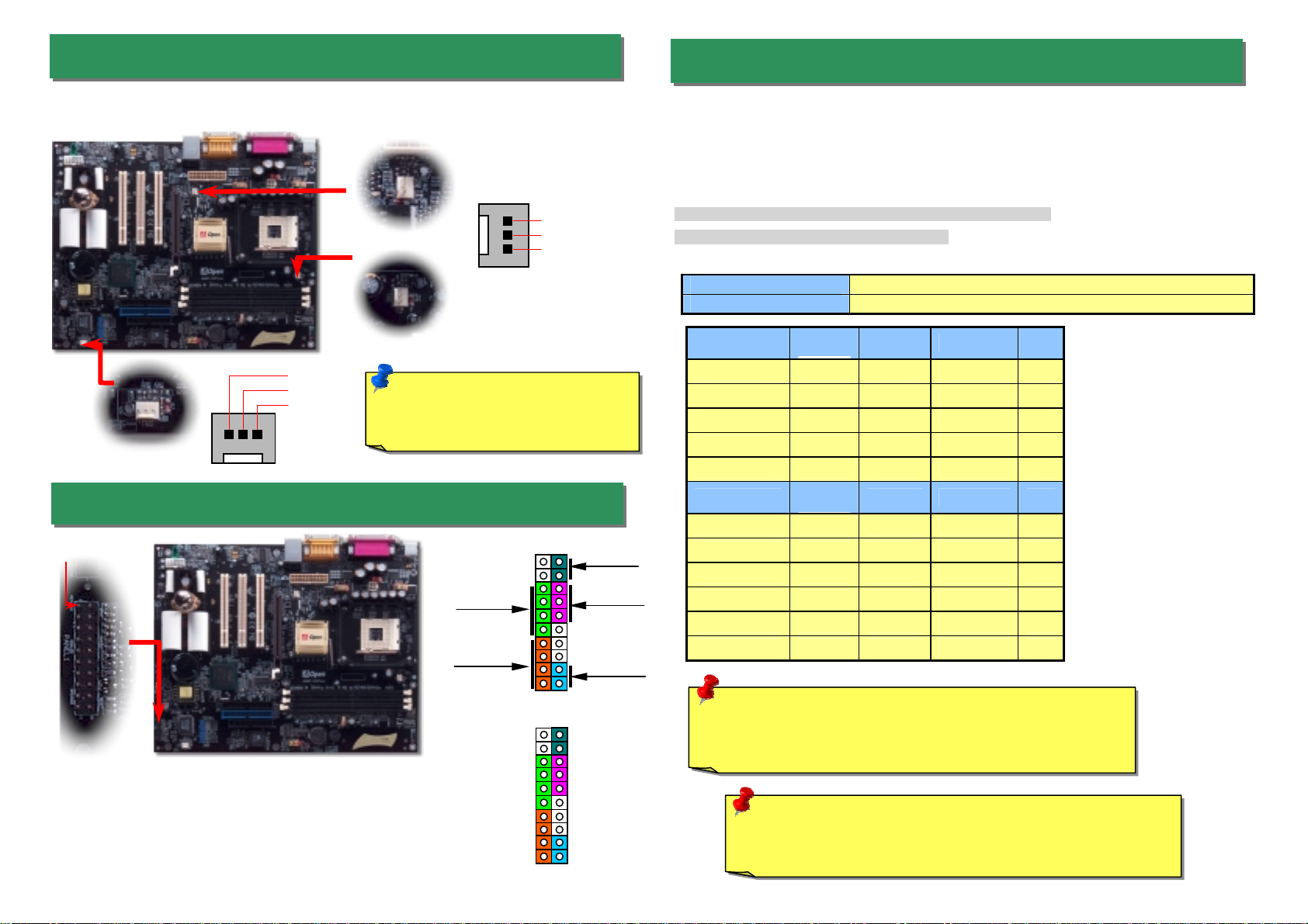
13. Connect IrDA Connector
The IrDA connector can be configured to support wireless infrared module, with this module
and application software such as Laplink or Windows 95 Direct Cable Connection, the use
r
can transfer files to or from laptops, notebooks, PDA devices and printers. This connecto
r
supports HPSIR (115.2Kbps, 2 meters) and ASK-IR (56Kbps).
Install the infrared module onto the IrDA connector and enable the infrared function from BIOS
Setup, UART mode select, make sure to have the correct orientation when you plug in the
IrDA connector. Pin 1
12. Connecting CD and AUX Connector
The AUX-IN connector is used to connect MPEG
Audio cable from MPEG card to onboard sound.
The CD-IN connector is used to connect CDAudio
cable from CDROM or DVD drive to onboard sound.
A
U
X
-IN (Green) CD-IN (Black)
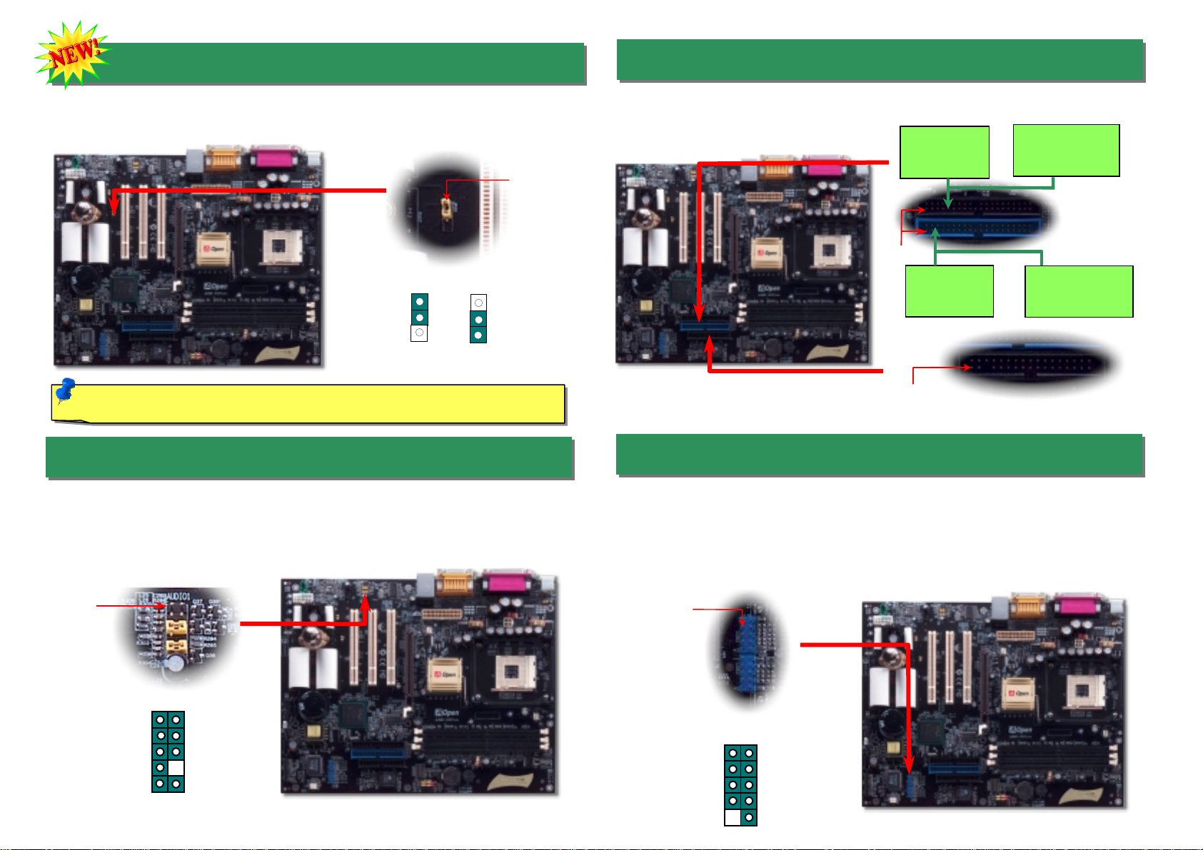
11. Dr. Voice II (Volume Adjustable)
The Dr. Voice is a great feature of this motherboard, which can identifies what kind of
problems had occurred in the operating system. It can even clearly “tell” whether there is a
component issue or an installed issue, such as CPU, memory module, VGA, PCI add-on
card, FDD, HDD or keyboard by voice. The Dr. Voice provides four kinds of language
versions, English, German, Japanese and Chinese for your choosing. You can select
preferred language version by JP15 & JP16 jumpers. However, if you want to disable this
function, you may also set JP1 and JP2 to pin 2-3 to disable to buzzer and speaker from
making out voices respectively.
JP15
Pin 1
JP15
Pin 1 JP16
Pin 1
English
(Default) Chinese Japanese German
JP2
JP1
JP16
Pin 1
1
KEY
GND
IR_RX
NC
+5
V
IR_T
X
IrDA Connector
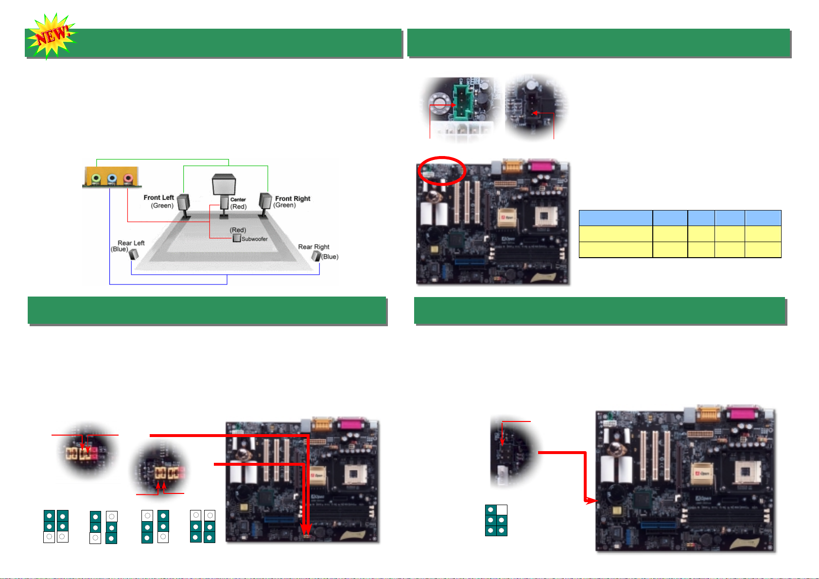
10. Super 5.1 Channel Audio Effect
This motherboard comes with an ALC650 CODEC, which supports high quality of 5.1 Channel
audio effects, bringing you a brand new audio experience. On the strength of the innovative
design of ALC650, you're able to use standard line-jacks for surround audio output withou
t
connecting any external module. To apply this function, you have to install the audio driver in
the Bonus Pack CD as well as an audio application supporting 5.1 Channel. Picture bello
w
represents the standard location of all speakers in 5.1 Channel sound track. Please connec
t
the plug of your front speakers to the green “Speaker out” port, rear speakers’ plug to the blue
“Line in” port and both of the center and subwoofer speakers to the red “MIC in” port.
Other manuals for AX4B-533 Tube
4
Table of contents
Other AOpen Motherboard manuals

AOpen
AOpen AK79G-V Datasheet

AOpen
AOpen MK73LE-V Setup guide

AOpen
AOpen AX4B-533 Tube Datasheet

AOpen
AOpen MX4LR TV Setup guide

AOpen
AOpen MK79G-N Setup guide

AOpen
AOpen i945Ga-PHS User manual

AOpen
AOpen vK8T800a-LF User manual

AOpen
AOpen MX59 Pro User manual

AOpen
AOpen MX46 U2 Setup guide

AOpen
AOpen AX4PE Tube-G User manual

AOpen
AOpen AK75 Setup guide

AOpen
AOpen AK79G TUBE Setup guide

AOpen
AOpen AX45-8X Max Setup guide

AOpen
AOpen AX45-4D MAX Datasheet

AOpen
AOpen AK33 M Setup guide

AOpen
AOpen AX4B Max Datasheet

AOpen
AOpen I915GAPLF-0410A User manual

AOpen
AOpen AP53 User manual

AOpen
AOpen AX45-533 Max Datasheet

AOpen
AOpen AX4B-G2 Datasheet