AOpen MX4B Datasheet

CD-IN Connecto
r
FAN3 Connecto
r
Front Audio Connecto
r
MODEM-CN Connecto
r
CNR Expansion Slot
IrDA Connecto
r
Front Panel Connecto
r
FDD Connecto
r
Supports 2
nd
USB Connecto
r
JP14 CMOS Clear Jumpe
r
2Mbit Programmable Flash ROM
Resettable Fuse
478-pin CPU socket with Voltage and
Frequency Auto-detection that supports
Intel
®
Pentium
®
4 1.3~2.4GHz+ CPU
AGP 4x Expansion Slot
32-bit PCI Expansion Slot x3
CPU Fan Connector
184-pin DDR DIMM Socket x2
supports PC-200/266 DDR SDRAM
maximum up to 2 GB
Intel
®
845 chipset with MCH, ICH2
that supports LAN, Ultra ATA/100,
DDR SDRAM Solution
2200
μ
F Low ESR Capacitors
ATX Power Connector
ATA/33/66/100 IDE Connector x2
Intel 82562ET PHY onboard
4-pin 12V.ATX Power Connector
PS/2 Mouse
Connector SPP/EPP/ECP Parallel Port MIDI/Game Port
RJ45 LAN
Connector
(Optional)
MIC-In
Line-In
Speaker Out
PS/2 Keyboard
Connector COM 1 Port COM 2 Port
USB Port
FAN2 Connector
System LED
RealTek ALC201 AC’97 CODEC

This motherboard comes with a 20-pin ATX power connector and an extra 4-pin connector as shown below.
Make sure you plug in the right direction. We strongly recommend you to insert the 4-pin connector before
connecting the 20-pin connector.
1. JP14 Clear CMOS
Everything you need to boot this
motherboard is included in this
Easy Installation Guide. For more
information, a complete Online
User's Manual can be found in the
Bonus Pack CD Disc. Thanks for
the help of saving our earth.
PART NO: 49.88C01.002 DOC. NO: MX4B-EG-E0112B
You can clear CMOS to restore system default setting. To
clear the CMOS, follow the procedure below.
1. Turn off the system and unplug the AC power.
2. RemoveATX power cable from connector PWR2.
3. Locate JP14 and short pins 2-3 for a few seconds.
4. Return JP14 to its normal setting by shorting pin 1 & pin 2.
5. ConnectATX power cable back to connector PWR2.
Tip: When should I Clear CMOS?
1. Boot fail because of overclocking…
2. Forget password…
3. Troubleshooting…
2. Connecting ATX Power Connector
Motherboard x1
This Easy Installation Guide x1
80-wire IDE Cable x1
Floppy Disk Drive Cable x1
Retention Module x1
Bonus Pack CD x1
Pin 1
+5V
+5V
+5V
+5V
+3.3V
+3.3V
+3.3V
COM
COM COM
COM
COM COM
-5V
COM
-12V
PS-ON
PW-OK
+12V
5VSB
Ground
Ground
12V
12V
Pin1
1
Normal
(
default
)
1
Clear CMOS

1. Pull up the CPU socket lever and up to
90-degree angle.
2. Locate Pin 1 in the socket and look fo
r
a (golden) cut edge on the CPU uppe
r
interface. Match Pin 1 and cut edge.
Then insert the CPU into the socket.
3. Press down the CPU socket lever and
finish CPU installation.
Plug in the CPU fan cable to the 3-pin CPU FAN connector. If you have chassis fan, you
can also plug it on System Fan (FAN2) or AUX Fan (FAN3) connector.
CPU Ratio 8x, 9x, 10x… 21x, 22x, 23x, 24x
CPU FSB (By 1MHz Stepping) 100-150 MHz.
CPU CPU Core
Frequency FSB
Clock System
Bus Ratio
Pentium 4 1.3G 1300MHz 100MHz 400MHz 13x
Pentium 4 1.4G 1400MHz 100MHz 400MHz 14x
Pentium 4 1.5G 1500MHz 100MHz 400MHz 15x
Pentium 4 1.6G 1600MHz 100MHz 400MHz 16x
Pentium 4 1.7G 1700MHz 100MHz 400MHz 17x
Pentium 4 1.8G 1800MHz 100MHz 400MHz 18x
Pentium 4 1.9G 1900MHz 100MHz 400MHz 19x
Pentium 4 2G 2000MHz 100MHz 400MHz 20x
Pentium 4 2.2G 2200MHz 100MHz 400MHz 22x
Pentium 4 2.4G 2400MHz 100MHz 400MHz 24x
5. Setting CPU Voltage & Frequency
Setting CPU Core Voltage
This motherboard supports CPU VID function. The CPU core voltage will be automaticall
y
detected.
Setting CPU Frequency
This motherboard is CPU jumper-less design, you can set CPU frequency through the
BIOS setup, and no jumpers or switches are needed.
BIOS Setup > Frequency / Voltage Control > CPU Speed Setting
Core Frequency = CPU FSB Clock * CPU Ratio
3. Installing Processor
Note: If you do not match the CPU
socket Pin 1 and CPU cut edge well, it
may damage the CPU.
CPU socket lever
CPU Pin 1 and cut edge
Note: Some CPU fans do not have
sensor pin so they cannot support fan
monitoring.
CPU Fan Connector
GND
SENSOR +12V
Warning: Intel
®
845 chipset supports maximum 400MHz
(100MHz*4) system bus and 66MHz AGP clock; higher clock setting
may cause serious system damage.
4. Installing CPU & System Fan
FAN3 Connector
This socket supports Micro-FC-PGA2 package CPU, which is the latest CPU package
developed by Intel. Other forms of CPU package are impossible to be fitted in.
GND
+12V
SENSOR
FAN2 Connector

Secondary
Master (3rd)
Secondary
Slave (4th)
Pin 1
Primary
Slave (2nd) Primary
Master (1st)
1KEY
GND
IR_RX
NC
+5V
IR_TX
8. Connecting IDE and Floppy Cables
9. Connecting Front Panel Cable
7. Connect IrDA Connector
The IrDA connector can be configured to support wireless infrared module, with this
module and application software such as Laplink or Windows 95 Direct Cable
Connection, the user can transfer files to or from laptops, notebooks, PDA devices and
printers. This connector supports HPSIR (115.2Kbps, 2 meters) andASK-IR (56Kbps).
Install the infrared module onto the IrDA connector and enable the infrared function
from BIOS Setup, UART mode select, make sure to have the correct orientation when
you plug in the IrDA connector.
Connect 34-pin floppy cable and 40-pin, 80-wire IDE cable to floppy connector FDC and
IDE connector. Be careful of the pin1 orientation. Wrong orientation may cause system
damage.
Pin 1
ATA 33/66/100
IDE Connector
A
ttach the power LED, speaker, and reset switch connectors to
the corresponding pins. If you enable “Suspend Mode” item in
BIOS Setup, the ACPI & Power LED will keep flashing while the
system is in suspend mode.
Locate the power switch cable from your ATX housing. It is
2-pin female connector from the housing front panel. Plug this
connector to the soft-power switch connector marked SPWR.
Pin 1
FDD Connector
IDE 1 (Primary)
IDE 2 (Secondary)
6. Support 2
nd
USB Port
This motherboard provides four USB connectors to connect USB devices, such as mouse,
keyboard, modem, printer, etc. There are two connectors on the PC99 back panel. You
can use proper cable to connect the other USB connector to the back panel or front panel
of chassis.
USB2 Connector
Pin 1
IrDA Connector
1
Speaker
IDE LED
SPWR
A
CPI & PWR
LED
Reset
1
5VSB
SPWR
ACPI LED-
GND
ACPILED
NC
NC
GND
RESET
GND
GND
Keylock
+5V
IDE LED
IDE LED
+5V
+5V
GND
NC
SPEAKER
Pin 1
USBPWR0
USB_FP_P0-
USB_FP_P0+
GND
KEY
USBPWR0
USB_FP_P1-
USB_FP_P1+
GND
USB_FP_OC0
1 2

A
UD FPOUT R
AUD_GND
A
UD RET L
KE
Y
JS/AUD RE
T
-R
A
UD VCC
A
UD MIC
A
UD MIC BIAS NC
A
UD FPOUT L
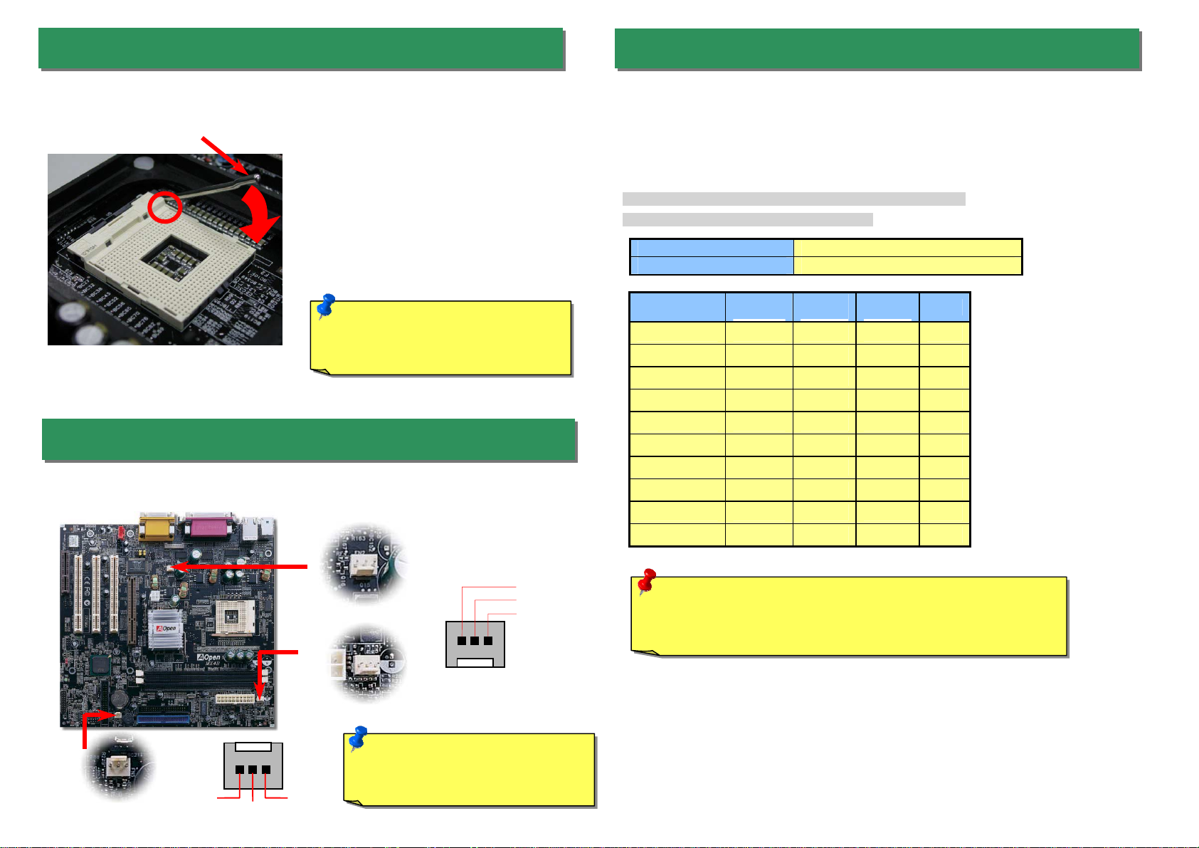
Connector Pin1 Pin2 Pin3 Pin4
MODEM-CN Mono In GND GND Mic Out
CD-IN Left GND GND Right
12. Connecting CD / MODEM Connector
10. Front Audio Connector
If the housing has been designed with an audio port on the front panel, you’ll be able to
connect onboard audio to front panel through this connector. By the way, please remove
5-6 and 9-10 jumper caps from the Front Audio Connector before connecting the cable.
Please do not remove these 5-6 and 9-10 yellow jumper caps if there’s no audio port on
the front panel.
The MODEM-CN connector is used to connect
Mono In/ Mic Out cable from internal modem card to
onboard sound circuit.
The CD-IN connector is used to connect CDAudio
cable from CDROM or DVD drive to onboard sound.
CD-IN (Black)
MODEM-CN (Red)
Pin 1
13. Installing LAN Driver (Optional)
The South Bridge in Intel 845 (Brookdale) chipset integrates a total communication solution including
10/100Mb Fast Ethernet for Office requirement. You can install LAN Driver under Windows95/98,
WindowsNT & Windows2000 by following steps.
ManuallyAdding anAdapter in Windows 95 / 98
=====================================
LOCATION OF DRIVER: \Intel\Driver\Lan\E100BNT5.SYS (NDIS 5.0)
LOCATION OF SETUP FILE: \Intel\Driver\Lan\NET82557.INF
1. From the Control Panel, double-click the “Add Hardware” icon.
2. Double-click Other Devices or Network Adapters in the list area.
3. Double-click a PCI Ethernet Controller.
4. Click the Driver tab, then click Update Driver.
5. Click Next at the Update Device Driver Wizard.
6. Select "Display a list of all the drivers..." and click Next.
7. Insert theAOpen Bonus CD and click Have Disk.
8. Enter the appropriate drive for your disk media
(for example: D:\) ,and click OK.
9. Click OK at the Select Device dialog box.
10. The Update Wizard displays the message that it has found
the driver. Click Next.
11. Click Finish and restart your computer when prompted.
Note: If the Ne
w
Hardware Foun
d
dialog box does no
t
appear at startup an
d
you cannot connect to
the network, check the
Device Manager list to
see if the new adapte
r
is present. If it is not,
p
lease install the LA
N
driver manually.
11. Support 10/100 Mbps LAN onboard (Optional)
Green/ACT
Orange/Speed
Intel 845 (Brookdale) chipset includes a fast Ethernet controller on chip. On the strength
of Intel 82562ET PHY on board, which is a highly-integrated Platform LAN Connect
device, it provides 10/100M bps Ethernet for office and home use, the Ethernet RJ45
connector is located on top of USB connectors. The green LED indicates the link mode, it
lights when linking to network and blinking when transferring data. The orange LED
indicates the transfer mode, and it lights when data is transferring in 100Mbps mode.

After you finish the setting of jumpers and connect correct cables. Power on
and enter the BIOS Setup, press <Del> during POST (Power On Self Test).
Choose "Load Setup Defaults" for recommended optimal performance.
14. Power-on and Load BIOS Setup
15. AOpen Bonus Pack CD 17. BIOS Upgrade
AOpen Easy Flash is more user-friendly than traditional flash method. The BIOS binary
file and flash routine are combined together and you simply run a single file to complete
the flash process.
1. Download new BIOS upgrade zipped file from AOpen's web site. For example,
MX4B102.ZIP.
2. Run shareware PKUNZIP (http://www.pkware.com) which supports
miscellaneous operation systems to extract the binary BIOS file and the flash
utility. Or Winzip (http://www.winzip.com/) in Windows environment.
3. Save the unzipped file into a bootable floppy disk.
For example, MX4B102.BIN & MX4B102.EXE
4. Reboot the system to DOS mode without loading any memory handler (such as
EMM386) or device driver. It needs around 520K free memory space.
5. Execute A:> MX4B102 and the program will do the rest of it.
DO NOT turn off the power during FLASH PROCESS until you are asked to!!
6. Reboot system and press <Del> to enter BIOS Setup, Choose "Load Setup
Defaults", then “Save & Exit Setup” and finish the BIOS upgrade.
Warning: The upgrade of new BIOS will permanently replace your original BIOS
content after flashing. The original BIOS setting and Win95/Win98 PnP information
will be refreshed and you probably need to re-configure your system.
16. Installing Onboard Sound Driver
You can use the autorun menu of Bonus CD disc. Choose the utility and driver and selec
t
model name.
Del
Warning: Please avoid of using "Load
Turbo Defaults", unless you are sure
your system components (CPU, DRAM,
HDD, etc.) are good enough for turbo
settin
g
.
This motherboard comes with a RealTek ALC201 AC97 CODEC, you can find the audio
driver from the Bonus Pack CD disc auto-run menu.

If you encounter any trouble to boot you system, follow the procedures
accordingly to resolve the problem.
Part Number and Serial Number
The Part Number and Serial number are printed on bar code label. You can find this
bar code label on the outside packing, on ISA/CPU slot or on component side of PCB.
For example:
Model name and BIOS version
MX4B R1.00 Feb. 01. 2001 AOpen Inc.
Award Plug and Play BIOS Extension v1.0A
Copyright © 1998, Award Software, Inc.
Model name and BIOS version can be found on upper left corner of first boot screen
(POST screen). For example:
MX4B is model name of motherboard; R1.00 is BIOS version
Make sure if the jumper settings for CPU and DRAMs are correct.
Clear CMOS.
Install the VGA card. Then connect your monitor and keyboard.
The problem was probably caused
by power supply or motherboard
failure. Please contact your reselle
r
or local distributor for repairing.
Perhaps your VGA card or monito
r
is defective.
No
Yes
No
Yes
It is very possible that your keyboard
is defective.
During system rebooting, press Del to enter BIOS Setup. Choose
“Load Setup Default".
The problem should be caused by the
IDE cables or HDD itself.
Re-install Windows 95, Windows 98 or Windows NT.
Yes
Yes
Turn off the power and unplug the AC power cable, then remove all
of the addon cards and cables, including VGA, IDE, FDD, COM1,
COM2 and Printer.
Turn on the power, and check if
the power supply and CPU fan
work properly.
Start
Check if there is display.
Press Ctrl, and Alt key at the
same time, hold them and then
press Del to see if the
s
y
stem reboots.
Turn off the system and
re-connect the IDE cable.
Check if the system can
reboot successfully.
End
No
No
P/N: 91.88110.201 is part number, S/N: 91949378KN73 is serial number.
Part No. Serial No.
Part No. Serial No.

Dear Customer,
Thanks for choosing AOpen products. To provide the best and fastest service to
our customer is our first priority. However, we receive numerous emails and
p
hone-calls worldwide everyday, it is very hard for us to serve everyone on time.
We recommend you follow the procedures below and seek help before contact
us. With your help, we can then continue to provide the best quality service to
more customers.
Thanks very much for your understanding!
A
Open Technical Supporting Team
Online Manual: Please check the manual carefully and make sure the
jumper settings and installation procedure are correct.
http://www.aopen.com/tech/download/manual/default.htm
1
1
Test Report: We recommend to choose board/card/device from the
compatibility test reports for assembling your PC.
http://www.aopen.com/tech/report/default.htm
2
2
FAQ: The latest FAQ (Frequently Asked Questions) may contain a
solution to your problem.
http://www.aopen.com/tech/faq/default.htm
5
5
Download Software: Check out this table to get the latest updated
BIOS/utility and drivers.
http://www.aopen.com/tech/download/default.htm
3
3
News Group: Your problem probably had been answered by our support
engineer or professional users on the news group.
http://www.aopen.com/tech/newsgrp/default.htm
4
4
6
6
Contact Us: Please prepare detail system configuration and error symptom
before contacting us. The part number, serial number and BIOS version
are also very helpful.
7
7
Pacific Rim
AOpen Inc.
Tel: 886-2-3789-5888
Fax: 886-2-3789-5899
America
AOpen America Inc.
Tel: 1-408-922-2100
Fax: 1-408-922-2935
Europe
AOpen Computer b.v.
Tel: 31-73-645-9516
Fax: 31-73-645-9604
Germany
AOpen Computer GmbH.
Tel: 49-2102-157700
Fax: 49-2102-157799
China
艾尔鹏国际上海(股)有限公司
Tel: 86-21-6225-8622
Fax: 86-21-6225-7926
Japan
AOpen Japan Inc.
Tel: 81-048-290-1800
Fax: 81-048-290-1820 Contact Distributors/Resellers: We sell our products through resellers
and integrators. They should know your system configuration very well and
should be able to solve your problem efficiently and provide important
reference for you if next time you want to buy something else from them.
Web Site: http://www.aopen.com
E-mail: Send us email by going through the contact form below.
English http://www.aopen.com/tech/contact/techusa.htm
Japanese http://www.aopen.co.jp/tech/contact/techjp.htm
Chinese http://www.aopen.com.tw/tech/contact/techtw.htm
German http://www.aopencom.de/tech/contact/techde.htm
French http:/france.aopen.com/tech/contact/techfr.htm
Simplified Chinese http://www.aopen.com.cn/tech/contact/techcn.htm
Other manuals for MX4B
1
Table of contents
Other AOpen Motherboard manuals