AOR ARD9800 Instruction Manual

FAST RADIO MODEM
ARD9800
ARD9800ARD9800
ARD9800
Instruction Manual
Multi-Mode And Digital Voice Interface
AOR, LTD.
Authority On Radio communications
American Communication Systems
Discover the Power of Comm unications
™
TO ORDER –VISIT
http://www.ameradio.com

1
ThankyouforpurchasingtheAORARD9800 MultimodeandDigitalVoiceInterface.
TheARD9800 isdesignedtoconvertyourHFradioequipmenttoamultimodeanddigitalvoice
capableradiowithoutperforminganymodificationstoyourtransceiver.
Pleasereadthroughthisinstructionmanualandfamiliarizeyourselfwiththeoperationofthe ARD9800.
Wesuggestyoukeepthisinstructionmanualforfuturereference.
WebelieveyouwillenjoyusingtheARD9800asanenhancementtoyourenjoymentofamateurradio.
AOR, LTD.

2
Features:
Digitalvoicecommunicationsusingexistinganalog2wayradios.
TheARD9800usesthesameaudiofrequencies(300Hz~2500Hz)asmicrophoneaudioto
modulatethevoicesignal. Thisallowsyoutouseananalog radioasadigitalvoicetransceiver.
DigitalvoicecommunicationsintheSingleSideBand(SSB)mode.
Theautomaticfrequencyclarifierfunctionadjustsfrequencydriftautomaticallyinthe SSBmode.
(Approximatelyupto+/-125Hz). UtilizestheODFM(MultiCarrierModulation)circuitthatiseffective
againstMulti-pathor SelectiveFading.
Automaticdigitalreceive
Automaticvoicesignaldetector recognizesthereceivedsignalasanalogordigital,automatically
switchingtotheappropriatemode.
DigitalSlowScanTV (SSTV) --Optionalmemorymodule(VM9800)required
Built-invideocapturefunction(NTSC). CompressesthesignalintoouroriginaladaptiveJPEGformat.
Sendandreceiveimages (similartoanalog slowscanTV)intheDigitalmode.Built-invideooutput
connector(NTSC)allowsviewingthepictureonanexternalmonitor.
Built–inhighgradeVocoder(AMBE)
Utilizinghighgradedigitalvoicecompression;deliversqualitydigitalvoicecommunications.
Built-inFECerrorcorrection
Apowerfulerrorcorrectioncircuitdeliversstableandreliablecommunications.
DatacommunicationsontheHFband
DatacommunicationispossibleontheHF(Highfrequency)bandsatnoextracost.(Speedmaybe
limitedbyregulationsin certainjurisdictions.)
Smallandcompactunit.Easytooperate.
SimplyconnecttheARD9800tothe microphonejack.Nocomplicatedorriskyradiomodificationsare
necessary.
UtilizesauniquelydesignedhighperformanceDSP(DigitalSignalProcessor)engine
Batteryoperationforfielduse.

3
Information to the Digital Device user required bythe FCC
ThisequipmenthasbeentestedandfoundtocomplywiththelimitsforaClassBdigitaldevice,pursuanttoPart
15oftheFCCRules. Theselimitsaredesignedtoprovidereasonableprotectionagainstharmfulinterferenceina
residentialinstallation.
Thisequipmentgenerates,usesandcangenerateradiofrequencyenergyand,ifnotinstalledandusedin
accordancewiththeinstructions,maycauseharmfulinterferencetoradiocommunications. However,thereisno
guaranteethattheinterferencewillnotoccurinaparticularinstallation. Ifthisequipmentdoescauseharmful
interferencetoradioortelevisionreception,whichcanbedeterminedbyturningtheequipmentoffandon,theuser
isencouragedtotrytocorrectthe interferencebyoneormoreofthefollowingmeasures:
Reorientorrelocatethereceivingantenna.
Increasethe separationbetweentheequipmentandreceiver.
Connecttheequipmenttoanoutletonacircuitdifferentfromthattowhichthereceiverisconnected.
Consultthedealerfortechnicalassistance.
Precautions
Topreventfire,personalinjury,orunitdamage,pleaseobservethe followingprecautions:
Donotattempttoadjustthisunitunlessinstructedtodosobythismanual.
Donotexposetheunittodirectsunlightorplacetheunitclosetoheatingappliances.
Donotplacetheunitinexcessivelydusty,humid,wetareas.
Wearenotresponsibleforanydamagestotheradioequipmentduetoimpropersettingsorinterface.
Wearenotresponsibleforanylossofcommunicationsduetoanunexpected changeofpropagationor
operatingenvironment.

4
Table of Contents
Page
SuppliedAccessories----------------------------------------------------------- 5
Controlsandfunctions --------------------------------------------------------- 5
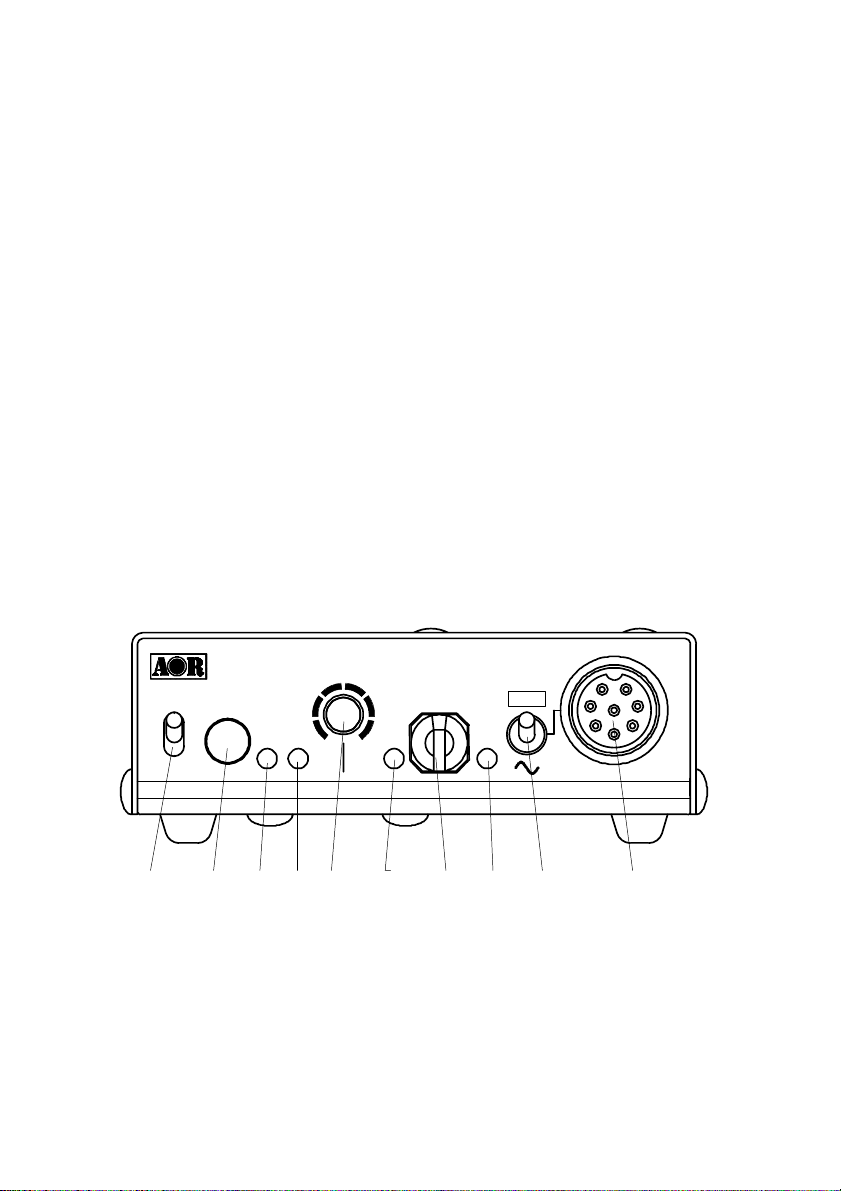
FrontPanel ------------------------------------------------------------------- 5
RearPanel -------------------------------------------------------------------- 8
TopPanel ----------------------------------------------------------------------- 12
InternalView ------------------------------------------------------------------ 12
BottomView ------------------------------------------------------------------ 14
InterfacingtheARD9800 ------------------------------------------------------ 15
ConnectiontoaRadio ----------------------------------------------------- 15
ConnectiontoaMicrophone -------------------------------------------- 16
Connectiontoa PC -------------------------------------------------------- 16
ConnectiontoaPowersupply ----------------------------------------- 17
ConnectiontoanExternalspeaker ---------------------------------- 17
LevelAdjustment ---------------------------------------------------------------- 17
Microphonelevel ------------------------------------------------------------ 17
RadioInputlevel ------------------------------------------------------------- 18
MicrophoneBalance ------------------------------------------------------- 18
Operation----------------------------------------------------------------------------- 19
Voice Communication ----------------------------------------------------- 19
DigitalVoiceCommunication ----------------------------------- 19
AnalogVoiceCommunication --------------------------------- 19
DataCommunication ------------------------------------------------------ 19
Receive ------------------------------------------------------------------ 19
Transmit ------------------------------------------------------------------ 20
DigitalImageCommunication ------------------------------------------ 21
Receive ------------------------------------------------------------------ 21
Transmit ----------------------------------------------------------------- 21
Specifications ------------------------------------------------------------------------ 22
ControlCommands -------------------------------------------------------------- 23
LimitedWarranty ------------------------------------------------------------------ 31

5
SuppliedAccessories
Thefollowingitemsareprovidedinthebox:
Accessory Quantity
----------------------------------------------------------------
Microphone 1
PCinterfacecable 1
SpeakerCable 1
DCPowercable 1
MicrophoneConnector 1
Instructionmanual (thisbooklet) 1
Controlsandfunctions
FrontPanel
a. Poweron/offswitch
b. TXswitch
(Note: Thisfunctionisavailableonlywhenanoptionalmemorymodulehasbeeninstalled.)
Pressthisswitchtocaptureandsendanimage.
WhentheVideoThroughFunctionis activated(AVTcommandisON),pressingthis
S
SS
SP
PP
PL
LL
LE
EE
EV
VV
VT
TT
TX
XX
XS
SS
ST
TT
TA
AA
AM
MM
MO
OO
OD
DD
DE
EE
E
M
MM
MI
II
IC
CC
C
B
BB
BU
UU
US
SS
S
O
OO
OV
VV
VE
EE
ER
RR
R
P
PP
PO
OO
OW
WW
WE
EE
ER
RR
R
DRA
0089
1
11
10
00
01
11
10
00
01
11
1
|
○
MMFEDOOIDARTSA
MaxMin
8
7
6
5
4
3
2
1
F
C
D
E
B
A
9
abc d efghij

6
switchwillenableoutputofthevideosignalconnectedtotheVideoInputtoalsobesent
tothevideooutputport,sothatyoucanmonitorthevideoimage.Pressthisswitchagain
tocaptureandsendtheimagethroughtheradioequipment.
WhentheVideoThroughFunctionis de-activated(AVTcommandisOFF),pressing
thisswitchwillautomaticallycapturethevideoimageandthentransmititthroughthe
radioequipment.
Refer to:Operation --DigitalImageCommunicationatpage21fordetails.
c. 2colorLED
Steadyreddisplay----Theunitisinthetransmitmode
Flashingred--Flashesredwhiletheheaderinformationisbeingsentwheninthedigital
communicationmode. (approximatelyonesecond).
Litingreen--Theunitisinthereceivemode
Notlit ---------Theunitisinthestandbyreceivemodeorintheanalogvoicereceivemode.
d. StatusLED(STA LED)
Inthedatacommunicationmode,litwhileunsentdatais inthememory. Itislitwhenthe
VideoThroughFunctionisactivated(DigitalImageCommunicationmode). Whenthe
VideoThroughFunctionisde-activated(AVTcommandisOFF),thisLEDwillnotbelit.
e. Speakervolumeadjustment
Adjustmentfortheinternalspeakeroutputlevelortheexternalspeakeroutputlevelwhenit
isconnected.
f. OperationModeLED(3 colors)
Indicatesthecurrentoperationmode:
Greendisplay-----DigitalVoicemode
Reddisplay -------AnalogVoicemode
Orangedisplay -- DataCommunicationmode
Notlit ---------------- DigitalImageCommunicationmode
g. MicrophoneInputLevelAdjustment
Adjustmentformicrophoneinputlevel

7
(Thisadjustmentmayberequiredwhenusingamicrophoneotherthantheonethatcame
withyourAR9800.)
RefertoMicrophoneLevelAdjustment at page17fordetails.
Incaseofunbalancedlevelsbetweenanalogvoiceanddigitalvoice,performa
microphonebalanceadjustmentasdescribedbelow.
MicrophoneBalance
1. Atfirst,setthepropermicrophonelevelinthedigital voicemode.
2. TurnoffthepowertotheARD9800.Pressand holdtheTXswitchthen turnthe
powerbackon.TheModeLEDshouldflashinorangecolorindicatingthe
ARD9800isin themicrophonebalanceadjustmentmode.
3. HoldingthePTTswitch,andwhilespeakinginto themicrophone,adjust the
microphonelevel.
4. Afterthe adjustmentiscompleted, pushtheTXswitchtosavethe newsetting.The
STALEDwilllighttoindicate thesettingprocess iscompleted.
5. Tocomplete theoperation,turn thepoweroftheARD9800off,andturnbackiton.
h. Overloadindicator
Litwhenthemicrophoneinputisoverloaded(toohigh).
ApropermicrophoneinputlevelwillcausetheLEDtoflashfromtimetotimewhen
speakingintothemicrophoneatanormallevel.
Themicrophonelevelcanbeadjustedwiththemicrophonelevelcontroller.
RefertoMicrophoneLevelAdjustment at page17fordetails.
i. Modeswitch
Select theDigitalvoicemode(10101)ortheAnalogvoicemode(~)
WhentheAnalogvoicemode(~)isselected,ordinaryanalogvoicecommunicationswill
bemade. Inthereceivemode,however,theARD9800willautomaticallydetectthemode
oftheincomingsignalanddecodesignalsaccordingly.TheLEDindicatestherespective
operationmode.

8
j. Microphoneconnector
Connectthesuppliedmicrophonetothisconnector.
Belowarethepinassignmentsoftheconnector.
1. Speakeroutput -- Monitoroutputsignalispresentatthispin.
2. BIAS--Powersourceforanelectretcondensertypeofmicrophone.
5VDCthrough2.2Kohm ofresistor
3. GND--Chassisground
4. TX
Takingthispintothegroundwillenablethetransmitmode.
(SameoperationastheTXswitchonthefrontpanel.)
5. D/A
Takingthispintothegroundwillforcetheunittothedigitalvoicecommunication
mode.Whenthispinisleftopen,theoperationmodewillbesetbythe mode
switchonthefrontpanel.
6. MICPTT--PTT(PushToTalk)input.
7. MICGND-- Microphonegroundsignal
8. MICIN-- Microphonesignalinput
RearPanel
SP
DC IN
AOR,LTD.
+‑
OUT
IN
RADIO
IN OUT
VIDEO
klm n opq r

9
k. CommunicationConnector(mini DIN8 pin)
AcommunicationconnectorforPC (RS-232C)
PinNumber Signal SignalDirection
1 TX ARD9800PC
2 DTR ARD9800PC
3 DSR ARD9800PC
4 GND GND
5 RX ARD9800PC
6 RTS ARD9800 PC
7 CTS ARD9800 PC
8 NC NoConnection
Shell FG Frameground
BaudRate: 9600
Startbit: 1
Stopbit: 1
Parity: None
Synchronization: Asynchronous
Flowcontrol: Hardware
l. VIDEO-IN connector (NTSC1V p–p, 75ohm)
Connectavideosignalsourcesuchasavideocamera,VCRoutput,etc.
m. VIDEO–OUTconnector(NTSC1Vp–p,75ohm)
Connectavideomonitortothisconnectortomonitorareceivedimageorapicturetobesent.
n. RADIOConnector
Usingthesupplied8pinconnector, connecttheARD9800toyourradioequipment. Youwill
needtowireacableaccordingtothemicrophoneconnectorspecificationsofyourradio.
BelowarethepinassignmentsoftheconnectorontheARD9800.

10
Pinnumber Signal Details
1 MICGND Microphoneground
2 MICIN MicrophoneInput
3 PTT PTT(PushTo Talk)input
4 GND PTTground
5 NC Noconnection
6 NC Noconnection
7 GND Ground
8 NC Noconnection
Note: MICGNDand GNDmustnotbeconnectedtogetherintheARD9800connector,or
RFfeedbackwillresult.
o. SPINConnector (3.5mmmonojack)
Connecttotheradioequipment’sspeakerjack. (Inputlevel:0.5 V–5Vp-p)
Note: Theoutputsignalfromaradio’s“accessory”connectormaynotbesufficienttousefor
thispurpose. Usethetransceiver’s“speakerout”jack.
p. SPOUTConnector(3.5mmmonojack)
Connectanexternalspeakertothisjacktodisableinternalspeaker.
q. DCINConnector (EIAJType4)
Connecttoaregulatedpowersupply. (10.7~16.0VDC,Centerpin–positive)Forlowervoltage
batteryoperation,settheinternaljumperterminalforbatteryoperation,andthenconnectexternal
batteries.

11
Ifyouhavechangedtheinternaljumperforlow-voltagebatteryoperation,
batteryvoltagemustbewithintherangeof 5.6~6.5VDC.DONOTapply
12.0Vorseveredamagewillresult,andthewarrantywillbevoid!
Note:Nolowbatteryvoltagedetectoris built-intheARD9800.
r. FG
Frameground

12
TopPanel
s. InternalSpeaker
InternalView
t. Factorysettingjumper
Mustbeset between2-3. (Donotchange thissettingat anytime.)
w
u
t
x
v
s

13
u. Optional Memorymoduleconnector
InsertanoptionalMemorymoduletouseDigitalSSTVfunctions.
RefertoMemoryModuleInstallationManualfordetails.
v. Batteryoperationselector
Placethejumperbetween1–2 (NOR)for normaloperation.
Changeitbetween2-3 (BATT)forbatteryoperation.
Ifyouhavechangedtheinternaljumperforlow-voltagebatteryoperation,
batteryvoltagemustbewithintherangeof 5.6~6.5VDC.DONOTapply
12.0Vorseveredamagewillresult,andthewarrantywillbevoid!
Note:Nolowbatteryvoltagedetectoris built-intheARD9800.
w. Internal speakersetting
Jumpersetting
1–2 Activatesinternalspeaker(default)
2--3 Disableinternalspeaker
Speakeroutputisalsoavailablefromthe pin#1of themicrophoneconnector.
Note:TheSPOUT(externalspeakeroutput)haspriorityregardlessoftheabovejumper
setting.
x. Outputlevelsetting
Jumpersetting
1–2 Normallevel(default) (LOW)
2–3 Highlevel(HIGH)
Incasethemicrophoneoutputlevelis toolowtodriveyourradio equipment,
placethejumpertothe2-3position.
RefertoMicrophoneLevelAdjustment at page17fordetails.

14
BottomView
y. Microphoneoutput level
RefertoLevelAdjustment RadioInputLevelat page18 fordetails
InterfacingtheARD9800
ConnectiontoaRadio
BeforeusingyourARD9800,youwillfirst needtowirethecablebetweenyourradio
equipmentandtheARD9800.
Foryourconvenience,an8-pinofamicrophoneconnectorfortheARD9800isincluded.
Youwillneedtoprepare,however,yourownmicrophoneconnector foryourradio
equipment.
y

15
Belowarethepinassignmentsofthe8-pinRADIOconnectorontherearpanelofthe
ARD9800.
Pinnumber Signal Details
1 MICGND Microphoneground
2 MICOUT MicrophoneOutput
3 PTT(H) PTT(PushTo Talk)Output(H level)
4 PTT(L) PTT(PushTo Talk)Output(Lowlevel)
5 NC Noconnection
6 NC Noconnection
7 GND Ground
8 NC Noconnection
Note: MICGNDand GNDmustnotbeconnectedtogetherintheARD9800connector,orRF
feedbackwillresult.

16
ConnectiontoaMicrophone
AspeakermicrophoneisincludedwithyourARD9800. However,ifyouwishto useyourown
microphonewiththeARD9800,youmaydo sobywiringyourmicrophonetocorrelatewiththeinput
jackoftheARD9800.BelowarethepinassignmentsoftheMicrophoneconnectoroftheARD9800.
1. Speakeroutput
Monitoroutputsignal ispresentat thispin.
2. BIAS
Powersourceforanelectletcondensertypeofmicrophone.
5VDCthrough2.2K ohmofresistor
3. GND
Chassisground
4. TX
Takingthispintothegroundwillenabletotransmit.
(SameoperationastheTXswitchonthefrontpanel.)
5. D/A
TakingthispintothegroundwillforcetheARD9800totheDigitalvoice
communicationmode.
Whenthispinisleftopen,theoperationmodewillbesetbythemodeswitchon
thefrontpanel.
6. MICPTT
PTT(PushToTalk)input.
7. MICGND
Microphonegroundsignal
8. MICIN
Microphonesignalinput
ConnectiontoaPC
APC interfacecableisincludedwiththeARD9800.
Parametersettingscanbemadebyusingterminalsoftware.
RefertoControl Commandsat page 23 fordetails

17
ConnectiontoaPowerSupply
Tooperate yourARD9800,usearegulatedpowersupply.
Theoperatingvoltagemustbewithintherangeof10.7~16.0VDC (approximately200mA).
ADCpowercableisalsoincludedwiththeARD9800.
Color Polarity
========================
RED Positive(+)
BLACK Negative(-)
RefertoInternalView:Batteryoperationat page12fordetails
Ifyouhavechangedtheinternaljumperforlow-voltagebatteryoperation,
suppliedvoltagemustbe withintherangeof5.6~6.5VDC.DONOTapply
12.0 Vor severedamage willresult, andthe warrantywillbe void!
Note:Thereis nolowbatteryvoltagedetectorbuilt-intotheARD9800.
.
ConnectiontoanExternalSpeaker
Ifanexternalspeakerisdesired, connectitto theSPOUTjack.Thiswillalsodisabletheinternal
speaker.
LevelAdjustment
MicrophoneLevel
Themicrophonelevelhasbeenproperlyadjustedatthefactorywiththeprovidedmicrophone.
Therefore,nofurtheradjustmentisneededfornormaloperation.
Ifyouwishtouseyourownmicrophoneratherthantheincludedone,youwillneed towireyour
microphoneconnectortomatchthepinsoftheARD9800,andthenadjustthemicrophonelevelas
describedinthefollowingsteps:

18
1. ConnectyourmicrophonetotheMicrophoneconnectoroftheARD9800.
2. Turnthe[LEV]knobfullycounterclockwise.
3. PressandholdthePTTswitchof themicrophone,and speakintomicrophone normally.
4. Slowlyturnthe[LEV]clockwiseuntilthe[OVER]LEDflashesoccasionally,withthepeaksof
yourvoicesignal.
RadioInputLevel
Performthefollowingstepstoadjusttheradioinputlevelofyourradioequipment:
1. ConnectthemicrophonetotheARD9800,andthenconnecttheARD9800toyourradio
equipment. Finally,ConnecttheARD9800toapowersupply.
2. TurntheoutputleveladjustmentonthebottomoftheARD9800fullycounterclockwise.Turn
thepowerontotheARD9800. Turnthepowerontoyourradioequipment.
3. SetthemodeswitchtotheDigitalmode[10101].
4. Pressthe [PTT]switchto transmitfromthe radioequipment.
5. AdjustthemicrophonegainoftheradioequipmentuntiltheALCfunctionjustactivates.
6. Ifthemicrophonegainistoolow,readjusttheoutputlevelonthe bottomofthe ARD9800.
MicrophoneBalance
Iftheoutputlevelofanalogvoiceanddigitalvoicearenotequal,anadjustmentcanbemade.To
adjusttheaudiobalance,performthefollowingsteps:
1. First,setthepropermicrophonelevelin thedigitalvoicemode.
2. TurnoffthepowertotheARD9800. PressandholdtheTXswitchthenturnthepowerback
on.TheMODELEDshould beblinkingorange, indicatingtheARD9800isin the
microphonebalanceadjustmentmode.
3. Holding the PTT switch, and while speaking into the microphone, adjust the microphone
level.
4. Aftertheadjustmentiscompleted,pushtheTXswitchtosavethenewsetting.TheSTALED
willlighttoindicatethesettingprocessiscompleted.
5. Tocomplete theoperation,turn thepoweroftheARD9800off,andthenturnbackiton.

19
Operations
Note:Alladjustmentsmustbeproperlyperformed before operation.
VoiceCommunication
YourARD9800iscapableofDigitalVoiceCommunicationsandAnalogVoiceCommunication.
Inthereceivemode,theARD9800willautomaticallyrecognizethetypeofcommunication,andsetthe
appropriateoperationmode.
Inthetransmitmode,theoperationmodecanbeselectedbyusingthe frontModeswitch.
DigitalVoiceCommunication
Setthemodeswitch [10101-~]upwardtothedigitalmodeposition. [10101]
Pressand holdthePTTswitchofthemicrophone. TheSTA(Status)LEDwillflashforabout0ne(1)
secondwhilesendingadataheadersignal.
WhentheLEDstopsflashing, speakintothe microphonenormally.
AnalogVoiceCommunication
Setthemodeswitch [10101- ~] downwardtotheanalogmodeposition. [~]PressandholdthePTT
switchofthemicrophone,andspeakintothemicrophonenormally.
DataCommunication
Runaterminalsoftwareprogramto controltheARD9800,andto entercontrolcommands.
RefertoControlCommandsat page 23fordetails
Twodifferenttypesofdata,ASCIIdataorbinarydata,can beused.
Bothdatacanbemixedas communicationdata.
Receive
Enterthecommand[ACO]togointotheconversemode.
ThereceivedvaliddatawillbedecodedanddisplayedonthePCscreen.
Ifreceiveddatais missing,(whichmayoccurduringpoorpropagationconditions)“garbage”data
maybedisplayedonthePCscreen.
Other manuals for ARD9800
1
Table of contents
Other AOR Recording Equipment manuals
Popular Recording Equipment manuals by other brands

Fostex
Fostex DV-824 Owner's manual supplement

Focusrite Audio Engineering
Focusrite Audio Engineering vocaster one studio user guide

ENSONIQ
ENSONIQ DP/4+ Configuration manual

KB Devices
KB Devices State of the Loop user manual

SMC Networks
SMC Networks EX260 Series Operation manual

Saramonic
Saramonic SR-Q2 user manual