Rosendahl nanosyncs HD User manual

Instruction Manual
Rosendahl nanosyncs HD
Rosendahl nanosyncs HD is a professional video and audio
sync reference generator.
www.rosendahl-studiotechnik.com
- 1 -
Contents
1. Unpacking and Mounting into a 19" Rack page 2
2. Installation page 3
3. Front Panel page 4
4. Rear Panel page 6
5. Video Reference page ..8
6. SD/HD Video Generator Settings page 10
7. Audio Reference page 12
8. Sample Rate and Multipliers page 15
9. USB midi port, MTC and MMC page 16
10. Configuration Protection page 19
11. Updating the Firmware page 20
12. nanoSETUP software page 21
13. Declaration of Conformity page 23
14. Specifications page 24
- 0 -

2. Installation1. Unpacking and Mounting into a 19"Rack
Word clock cables should be under 20 metres to retain maximum
benefit from the nanosyncs HD ultra low jitter clocks.
The unit is shipped in two preset mains versions:
115VAC and 230VAC
The optimum solution is to mount the nanosyncs HD in the same 19“
rack as the most important AD/ DA digital audio converters in your
studio. These units should receive the lowest jitter sample clocks.
Please check the mains voltage marking on the original package
and the voltage label on the rear panel before you connect the
unit to mains.
If you require no more than the eight word clock outputs provided by
the nanosyncs HD feed each digital audio unit a separate clock line.
If you need more clock signals you should use a word clock
distribution unit such as the Rosendahl nanoclocks.
The voltage selection slide switch is on the left side of the unit and
covered by a plastic label to avoid accidentally changes.
The nanosyncs HD comes with the following accessories:
All video and word clock cables used must be 75 ohm coaxial
(RG59). Do not use 50 ohm coaxial computer network cables
(RG58).
1 pcs IEC mains cable
1 pcs USB cable, type A-B
1 pcs Instruction manual, that you are now reading
Most video and word clock inputs are internal terminated with 75
ohms. You can not connect two terminated inputs to one word clock
or video sync output using a BNC-T. Only if the inputs are switchable
or have no termination you can use BNC-Ts to connect multiple word
clock or video sync inputs. In this case use very short cables to link
the BNC-Ts. Ensure that only the last input of the chain is 75 ohm
terminated. Passive BNC-T links should not be used to link more
than 3 inputs. Please refer also to the instruction manuals of the
devices you connect to the nanosyncs audio clock and video sync
outputs.
Please check that all these items are present and contact your dealer
if anything is missing.
The nanosyncs HD housing is a standard 19" rackmount type, 1U
high.
Use four rackmount screws to mount the unit into a standard 19"
rack.
When necessary remove the bonded rubber foots on the bottom side.
Please do not mount your nanosyncs hd direct atop of equipment
with high heat emission. High ambient temperature can cause small
variations in the absolute tuning of the internal precision crystal
oscillator.
Make sure the used power socket is a 3-pole type with separate
ground conductor. Use only the provided or other 3-pole power
cables with international safety certificates.
- 2 - - 3 -

3. Front Panel
S1 L1 L2 L3 L4 L5 L6 L7 L8 L9 L10 L11 L12 L13 L14 S2 S3 S4
(S1) Power Switch: (L9) (L10) Sample Rate:
Switches the unit from standby power down mode to normal
operation mode and vice versa.
The base sample rate of the audio clock generator can be set to 44.1
or 48kHz. The blue locked LED indicates the audio lock status
according to the selected audio reference.
(L1) (L2) Video Reference: (L10) indicates applied word clock pull up or down rates: +4%
(25/24), +0.1% (1001/1000), -0.1% (1000/1001) or -4% (24/25).
The first four LEDs (L1) indicate the selected video reference.
INTERNAL, EXT.PAL, EXT.NTSC or EXT.TRI LEVEL.
The second column (L2) displays the detected frame rate. (L11) (L12) (L13) Multipliers:
To generate double or quad sample rates (88.2, 96, 76.4, 192 kHz) it
is possible to apply x2 or x4 multipliers accordingly.
(L3) SD Video Generator Standard:
The standard definition sync generator can be set to output NTSC,
PAL 25 or slow PAL 24 /23.98. The blue locked LED indicates that
the SD and HD video generators are genlocked to the selected video
reference.
WO1-6 (word clock outputs 1-6) are configured according (L11) to
output x1, x2 or x4 rates. Outputs WO 7-8 can be set to x1, x2, x4 or
x256 (digidesign super clock) rates shown in column (L12).
AES and SPDIF reference signals can be configured to output Fs x1
or x2 sample rates.
(L4) (L5) HD Video Generator Standard:
The high definition TRI LEVEL sync generator can be set to generate
1080i/psf 1080p x1, 1080p x2, 720p x2 or 720p x1 standards
according L4. The LEDs (L5) indicate the selected frame rate.
(L14) USB Status, Config. Protect:
LED LTC to MTC indicates the translation of LTC time code into MTC
sent via USB to a connected host computer.
(L6) SD/HD Select: LED MMC/MTC to LTC signalises the operation of the internal LTC
generator controlled by a connected host computer using MMC or
MTC protocol.
The six video outputs can be configured to output the SD or the HD
signal. VO1-3 (video outputs 1-3) are switched over together, outputs
VO4, VO5 and VO6 can be selected individually. LED CONFIG.PROTECT indicates that the configuration protect
mode is activated.
(L7) (L8) Audio Reference:
This field indicates the reference selection for the word clock and
AES/ SPDIF audio clock generator. Settings FOLLOW VIDEO, EXT.
WORD FS, EXT.WORD 1:1 and LTC FPS are possible under (L7).
(S2) (S3) (S4) Menu and Select Keys:
Use the Menu left and right keys (S3) (S4)(◄,►) to navigate through
the different fields. The parameters can be changed using the Select
key (S4). Press both menu keys (S3) (S4) to store all settings to non
volatile flash memory.
Column (L8) indicates the selected frame rate for LTC FPS mode or
the sample rate (FS) selected when set to EXT.WORD FS mode.
- 4 - - 5 -

4. Rear Panel
C1-C6 C7 C8 C9 C10 C11 C12-13 C14-C19 C20-C21 C22 C23
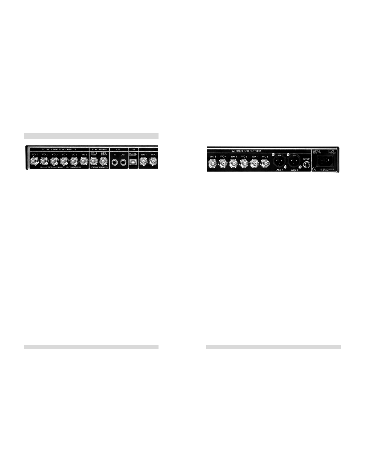
(C1- C6) SD/HD Video Sync Outputs (BNC): (C11) USB Port (USB type B):
Six video outputs VO1-VO6 are individually buffered to drive single
ended 75 ohm inputs. VO1-VO3, VO4, VO5, VO6 can be configured
to output standard definition sync signals or HD tri level reference
signals.
A USB 2.0 midi device class compliant interface allows plug and play
connectivity to MAC or PC host computers (Operating systems
Windows-XP or Mac-OSX are required for the midi device class
functionality). Supports MTC and MMC as well as Rosendahl Sysex
commands for remote and update functions.
(C7) Video Sync Input (BNC):
Both internal video generators can be genlocked to external video
references using this input. The video sync input accepts SD
standard definition video syncs as well as HD tri level syncs
according to the selected video reference source. This input is
internally 75 ohm terminated and requires standard video levels.
(300mV Sync, 300 mV Burst, +/- 300mV Tri Level).
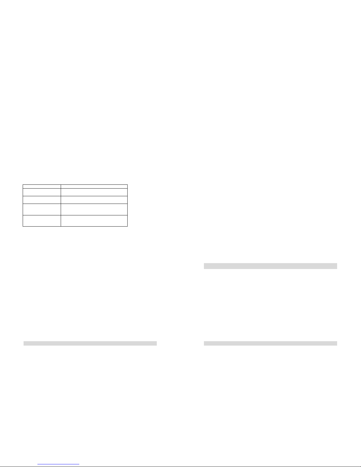
(C12- C19) Word Clock Outputs (BNC):
Word clock outputs WO1-WO6 can be configured to output base
sample rates (44.1/ 48 kHz) as well as x2 (88.2/ 96 kHz) or x4 (176.4/
192 kHz) rates. Outputs WO7-WO8 support x1, x2, x4 and also x256
(digidesign super clock) sample rates.
All outputs drive 3,5 Vpp into single ended 75 ohm inputs.
(C8) Word Clock Input (BNC):
The audio clock generator can be resolved to external word clock
signals. This input is internally 75 ohms terminated and accepts word
clock signals from 40-200 kHz at 1,5 - 5 Vpp levels.
(C20- C21) AES/ EBU Outputs (XLR 3-pin):
Two AES-3 clock reference outputs can be configured to generate
standard x1 (44.1/ 48 kHz) or x2 (88.2/ 96 kHz) sample rates. These
outputs are transformer balanced and drive 3,5 Vpp into standard
110 ohm inputs.
(C9) LTC Time Code Input (RCA):
LTC time code (also called SMPTE) is read by the nanosyncs HD
and translated into MTC via the USB midi port. The audio clock
generator can also be resolved to the LTC applied on this input.
(C22) SPDIF Output (RCA):
Timecode levels can vary from -40 to +20 dBu. This input is internally
terminated with 10k ohms (high impedance).
The IEC 985 SPDIF audio clock reference output can be configured
to provide standard x1 (44.1/ 48 kHz) or x2 (88.2/ 96 kHz) sample
rates. This output drives 0,5 Vpp into standard coaxial 75 ohm SPDIF
inputs.
(C10) LTC Time Code Output (RCA):
The LTC time code output has a fixed output level of 1Vpp. It can
drive low impedance inputs down to 600 ohms. To connect to XLR
time code inputs a standard audio adaptor cable (RCA to XLR) is
required.
(C23) Mains Socket (IEC):
Use the IEC mains cable supplied for connecting to an earthed mains
socket. Please see also page 4 "Unpacking…".
- 6 - - 7 -

5. Video Reference
EXT. NTSC: The unit locks to an external NTSC video reference
signal applied on the video sync input connector
(C7). The 30/60 and -0.1% LEDs in the video
reference section indicate that there is a video input
signal present at 29.97 fps. When the internal SD
generator is set to NTSC, the outputs will be 4 field
To navigate through the settings you must enter the setup mode by
pressing one of the MENU keys [◄] or [►].
The currently selected parameter section starts flashing to indicate
you are in the setup mode.
With the MENU buttons [◄] and [►] you can move form one section
to the next. When saving the settings, the menu position will also be
stored and reappears at the same position when the setup mode is
called up again.
and subcarrier genlocked to the NTSC video input
signal.
The blue LOCKED LED in the video section indicates
genlocked operation to an external NTSC reference.
Press both menu keys (S3) (S4) to exit the setup mode and store all
settings to non volatile flash memory.
A 30 fps "black & white" input signal is indicated by
the 30 fps LED without -0.1% LED.
The nanosyncs HD will also lock to 30 fps signals.
Enter the setup mode and select the video reference section.
EXT.TRI LEVEL:
INTERNAL: The internal 0.5 ppm accurate crystal oscillator is the
master for both video generators.
The unit locks to an external Tri Level Sync signal
applied on the video sync input connector (C7).
Blue LOCKED LED in the video section will be on.
An applied reference signal at the video sync input
connector will be ignored.
The four LEDs 24, 25/50, 30/60, -0.1% in the video
reference section indicate the automatically detected
input frame rate.
EXT. PAL: The unit locks to an external PAL video reference
signal applied on the video sync input connector
(C7). The 25/50 LED in the video reference section
indicates that there is a video input signal present at
25 fps. When the internal SD generator is set to
When the input frame rate matches the SD or HD
generator frame rate a phase lock will be performed
PAL 25 the outputs will be 8 field and subcarrier
genlocked to the PAL video input signal. (phase locked means that the according v-sync
patterns are reset exactly to the same position as
where the video input signal v-sync is located).
LEDs 24 or 24 and -0.1% indicate the detection of a
slow PAL reference at 24 or 23.98 fps.
The blue LOCKED LED in the video section indicates
genlocked operation to an external Tri Level
reference.
The blue LOCKED LED in the video section indicates
locked operation to external PAL references.
- 8 - - 9 -

6. SD / HD Video Generator Settings
1080 P x1: 1080 lines , progressive
The nanosyncs HD generates one SD video sync standard and one
HD tri level standard simultaneously. 23.98, 24, 25, 29.97, 30 fps rates
You can set the frame rates and formats independent for the SD and
HD generator section. 1080 P x2: 1080 lines , progressive
50, 59.94, 60 fps rates
Both standards are always frequency locked to the selected video
reference, also when the frame rates are different. 720 P x2: 720 lines , progressive
50, 59.94, 60 fps rates
When using the same frame rate (or double/ half rates) the standards
will also be phase locked together (phase locked means both v-sync
patterns start exactly at the same position).
720 P x1: 720 lines , progressive
23.98, 24, 25, 29.97, 30 fps rates
Go to the video generator FPS section to select the HD generator
base frame rate:
Enter the setup mode and select the SD STD. section.
Press the SELECT button to set the SD generator to NTSC, PAL 25
or PAL 24. 24 fps - 0.1% pull down film frame rate
24 fps standard film frame rate
25 fps European HDTV
NTSC : 525 lines 29,97 fps, SD used in the US, Japan 30 fps - 0.1% NTSC frame rate (30 pull down)
PAL 25: 625 lines 25 fps, SD used in Europe … 30 fps US/ Japan HDTV
PAL 24: 625 lines 24 fps, used for film postpro
PAL 23.98: 625 lines 23,98 fps, indicated by LEDs PAL 24 According to the standard listing above not all HD standards exist at
all frame rates. When you select a non-existing combination of STD
and FPS the hd video outputs are switched off and the FPS LEDs will
extinguish.
and NTSC simultaneously
Note: the generated PAL 24 signals do not insert a colour burst.
Select the HD STD. section to edit the generated HD tri level
standard, whereas "x2" indicates double frame rate as on display in
the FPS field (L8):
Go to the video generator SD/HD SELECT section to configure the
six video outputs VO1-VO6 (C1-C6):
VO1-VO3, VO4, VO5 and VO6 can be individually set to output the
SD or HD generator signal.
1080 I/PSF x2: 1080 lines, interlace or progressive
segmented frame
47.95, 48, 50, 59.94, 60 fps rates
In addition VO6 can be configured to output black Rosendahl bi-level
syncs for Dolby Encoder/ Decoders. See page 21 nanoSETUP
software for more details.
Note: For a sync signal there is no difference between both standards.
A progressive segmented frame means progressive scanned picture
contents are transferred within an interlace frame format.
- 10 - - 11 -

This functionality is a powerful tool when you need to convert a audio
project from one sample rate to an other using a sample rate
converter and your nanosyncs HD for locking both clocks together.
7. Audio Reference
Enter the setup mode and select the audio reference section. The input word clock is set with the four FPS leds in the audio
reference section and the output sample rate is set in the standard
sample rate and multiplier sections (see page 17).
(See page 10 for more informations how to navigate through the
different setup sections.)
The audio reference can be set to: The four FS LEDs in the audio reference section indicate the
selected external word clock sample rate.
FOLLOW VIDEO:
These LEDs are also used to indicate the selected frame rate for
audio reference mode = LTC and the denomination left of the slash
relates to the FPS value for LTC operation and the value right of the
slash relates to the operation mode external word FS.
The audio clock generator follows to the selected video reference.
If you want to use the nanosyncs HD as a studio master set the video
reference to INTERNAL and the audio reference to FOLLOW VIDEO.
To synchronise the audio clocks to an external video reference you
must slave the video section to this external video reference and set
the audio reference to follow video.
Example: In operation mode external word FS LEDs 25/48.0 and
30/x2 are on means the unit synchronises the audio clocks to an
external 96 kHz external word clock signal.
When one of the selected SD or HD video generator standards does
match an integer relationship with the selected word clock sample
rate (for example PAL and 48 kHz) the audio clock phase will be
adjusted to the video phase.
The blue LOCKED LED indicates the generation of gearbox locked
audio clock signals.
This means that the video’s start of picture will be phase locked to
the word clock signal. Thus synchronising several nanosyncs HD to
the same house sync reference will result in phase locked audio word
clocks between all units.
EXT. WORD 1:1:
Audio reference mode EXT WORD 1:1 regenerates the incoming
word clock sample rate from 40-200 kHz on all word clock outputs
1:1 (AES and SPDIF outputs are limited to Fs x2 rates up to 100
kHz).
The blue LOCKED LED indicates the generation of video locked
audio clock signals.
EXT. WORD FS: You can use nanosyncs HD as a word clock distributor which follows
to all incoming sample rates automatically with the advantage that all
clocks are regenerated. This results in highest clock quality on all
outputs independent of the word clock input signal used.
When you set the audio reference to external word clock FS, the
word clock generator resolves to a defined external word clock
frequency. The blue LOCKED LED indicates the locked 1:1 regeneration of
audio word clock signals.
In this operation mode you can select the generated sample rate
independent of the input sample rate.
You can synchronise for example a 44.1 kHz word clock signal to an
external 96 kHz word clock reference. This means the unit works as
an electronic gearbox to synchronise different sample rates together.
- 12 - - 13 -

8. Sample Rate and Multipliers
The sample rate and multipliers (section L9-L13) follow automaticallly
to the word clock input signal. When audio reference is set to to EXT
WORD 1:1 it is not possible to access the sample rate and multiplier
sections in the menu.
Enter the setup mode and select the sample rate section (L9).
(See page 10 for more informations how to navigate through the
different setup sections.)
LTC FPS: The base sample rate of the audio clock generator can be set to 44.1
or 48kHz.
The nanosyncs HD is also able to resolve audio word clock signals to
external, free running LTC time code signals.
The next section (L10) allows you to enter a so called pull factor.
These factors are special sample rates which are used in audio post
production to compensate frame rate differencies from video and film
standards.
Only forward running timecode within a +/- 10% window, is used as a
reference. The nanosyncs HD will perform a very slow calibration to
your time code source, which can take up to a half minute.
+4% (25/24) PAL / film
Once calibrated the nanosyncs HD will relock immediately to the
same speed as long as you do not change the sample rate or the
reference time code format.
+0.1% (1001/1000) 30 fps / NTSC
-0.1% (1000/1001) NTSC / 30
-4% (24/25) film / PAL
Once calibrated the nanosyncs HD will flywheel over looping,
ramping and low or high speed time code with no disturbance to the
audio clock outputs.
Note: For standard audio productions all four LEDs must be off.
Enter the setup mode and select the multipliers section (L11-L13).
LTC produced by analog tape recorders will be flywheeled to produce
a ultra low jitter synchronised audio clock. To generate double or quad sample rates (88.2, 96, 76.4, 192 kHz) it
is possible to apply x2 or x4 multipliers.
Select the used LTC time code standard stepping through the FPS
section in the audio reference field. WO1-6 (word clock outputs 1-6) are configured according (L11) to
output x1, x2 or x4 rates. Outputs WO 7-8 can be set to x1, x2, x4 or
x256 (digidesign super clock) shown in column (L12).
Four LEDs indicate
24 fps, 25 fps, 30 fps, -0.1% pull down The AES/EBU reference outputs can be set to x1 or x2 factors (L13).
The SPDIF reference output can be set to x1 or x2 factors (L13).
29.97 fps is on display with 30 fps and -0.1% LEDs
23.98 fps is on display with 24 fps and -0.1% LEDs
The blue LOCKED LED indicates the generation of LTC
synchronised audio clocks.
Drop or non-drop formats are irrelevant, because this is just a speed
synchronisation process.
- 14 - - 15 -

9. USB midi port, MMC and MTC
To synchronise a DAW to MTC time code open the nanosyncs HD
midi port in your DAW application software and make the according
settings. Please see also the instructions of your DAW software for
synchronisation to MTC.
The nanosyncs HD has a USB (Universal Serial Bus) port for
bidirectional communications with a host computer.
The nanosyncs HD firmware complies with the USB Device Class
Definition for MIDI Devices Release 1.0.
The LTC to MTC translation is an independent process in the
nanosyncs HD and works within all operation modes.
Current operating systems as Windows XP or Max OSX support the
MIDI device class and can be connected without installation of a
software driver.
When you use the nanosyncs HD as master clock (video reference
set to internal and audio reference set to follow video) you can still
use the LTC to MTC translation.
The nanosyncs HD unit is detected as Standard Audio Device (OSX
shows also the device name as nanosyncs HD). Example 1:
(1) A professional video machine is genlocked to the nanosyncs HD
video syncs.
Any application which uses MIDI ports can use the nanosyncs HD as
midi in or out port.
(2) A digital audio workstation (DAW) is slaved to the nanosyncs HD
word clocks. The nanosyncs HD audio reference is set to FOLLOW
VIDEO.
LTC to MTC:
Connect a LTC time code signal to the time code input (C9). The LTC
level can vary from -40 to +20 dBu.
(3) Your DAW software controls the video machine via 9-pin.
Forward running LTC in the range of +/- 10% of playspeed is
translated into MTC quarter messages. (4) The LTC output of the video machine is connected to the
nanosyncs HD and sent via USB to the DAW software as MTC.
All LTC formats are automatically detected and the equivalent MTC
format is used.
Example 2:
Time code signals running reverse or slower/ faster than the +/- 10%
range will be translated into MTC Full Messages. (1) An analog multitrack audio tape recorder with LTC time code
recorded on track 24 feeds LTC to the nanosyncs HD.
MTC Full Messages serve to spot a slaved DAW to the according
time code position whereas MTC quarter messages are used for
synchronisation at play speed.
(2) The nanosyncs HD audio reference is set to LTC.
(3) A digital audio workstation is slaved to the nanosyncs HD word
clocks/ super clocks.
The LTC TO MTC LED (column L14) indicates that LTC time code is
read and sent as MTC to the USB midi port.
(4) The DAW software receives time code from the tape machine
translated to MTC from the nanosyncs HD via USB.
- 16 - - 17 -

MMC/MTC to LTC:
Midi Machine Control (MMC) is a midi protocol to remote a video
machine or an audio recorder.
When the nanosyncs HD unit receives an MTC sent from a
application software of the host computer, the LTC Generator will
also be triggered to start generation.
Most DAW software applications are able to send MMC commands.
The nanosyncs HD accepts MMC commands via the USB to control
the integrated LTC time code generator (LTC output on C10).
This means a new detected MTC signal sets the LTC generator to
the corresponding position and starts the generator.
In firmware 1.0 the following MMC commands are implemented: Your DAW hardware must be slaved to the nanosyncs HD audio
clocks and the nanosyncs HD audio reference must be set to
FOLLOW VIDEO to make sure the DAW audio hardware and the
LTC generator are running at the same speed.
Command Description
F0 7F 7F 06 01 F7 MMC „stop“
stops the LTC generator
F0 7F 7F 06 02 F7 MMC „play“
starts the LTC time code generator
F0 7F 7F 06 03 F7 MMC „deferred play“
starts the time code generater after active
MCP (locate)
F0 7F 7F 06 44 06 01 hr
mn sc fr ff F7
MMC „locate“
sets generator to time code position
sets the LTC format
The MMC/MTC to LTC LED (column L14) indicates LTC generation.
Example:
(1) A digital audio workstation (DAW) is slaved to the nanosyncs HD
word clocks. The nanosyncs HD audio reference is set to FOLLOW
VIDEO. The nanosyncs HD is used as a studio master clock.
Note: When receiving MMC commands the internal time code
generator is referenced from the SD and HD video generators. When
a frame rate matches the time code standard, the LTC will also be
phase locked to the video generator.
(2) An audio mixing console requires LTC time code for its
automating.
The DAW sends MTC to the nanosyncs HD and the LTC generator
output feeds the audio mixing console.
Example:
For locked LTC generation from a DAW the audio reference must be
set to FOLLOW VIDEO and the DAW audio hardware must be slaved
to the nanosyncs HD word clocks.
10. Configuration Protection
To avoid unwanted changes in the nanosyncs HD setup (by
interested visitors for example) it is possible to protect the
configuration.
A free nanosyncs HD utility software (coming soon) will also allow to
set and start the LTC generator via MMC for using the nanosyncs HD
as a time of day LTC master generator. In the protected mode all keys are disabled.
LED CONFIG.PROTECT (L14) indicates active protection mode.
Note: 29.97 non drop frame rate is not defined in the MIDI protocol.
The nanosyncs HD generates 29.97 non drop rates when receiving
the 30 non drop format via MIDI and the SD generator is set to
NTSC. When set to PAL standard 30 fps non drop LTC is output.
To enable or disable protection mode hold both MENU keys (S2) +
(S3) down for about 6 seconds.
- 18 - - 19 -

11 . Firmware Update
A premature termination of the software update process leads to the
complete loss of the firmware but does not erase the nanosyncs HD
BIOS. Please switch the unit off and on again, use the PING
command and restart the firmware update procedure again.
The firmware version installed in your nanosyncs HD is displayed
every time the unit is switched on.
After the LED test (all LEDs on for about 1 second) the currently
installed firmware version is shown on the first two leftmost LED
columns for about 1 second in the format "n.m".
If a CRC error occurs, the software update process is stopped and is
indicated by all LEDs flashing in a slow 2 second beat (0,5 Hz).
First column reflects version digit "n", the second column is version
digit "m". After a successful firmware update the unit starts and shows the new
firmware version.
The previous menu settings are saved but should be verified, as the
new firmware possibly contains new features and settings.
Example:
Bottom LED column 1 and top LED column 2 are on: version 1.4.
To update the firmware you need a PC running Windows-XP or a
MAC with OSX.
12 . nanoSETUP Software
Go to www.nanosyncs.com and download the newest nanosyncs HD
firmware file (NFXXXX.DAT) and the nanoSETUP software for
Windows XP.
nanoSETUP is a free utility program running under Windows XP.
One or multiple nanosyncs units can be configured with this software.
The "PING" command detects automatically via USB connected
nanosyncs units.
Make a USB connection from your computer to the nanosyncs HD
using the supplied USB A-B cable.
In addition to the standard parameter settings it is possible to
configure special functions of the nanosyncs HD:
Now start the software "nanoSETUP". The serial number and
firmware version of the connected nanosyncs HD unit(s) are
displayed.
(1) NTSC Pedestals can be switched on/ off to set the black level of
SD NTSC sync signals to +7.5 IRE (as used in the USA).
(1) Select the update window under "Options -> Firmwareupdate".
(2) "Black Rosendahl on VO6" changes the HD trilevel sync output
on video output 6 (VO6) into a bi-level sync signal as used by Dolby
Encoders/ Decoders. The frame rate of this signal follows the
selected HD standard setting.
(2) Load a valid firmware file NFXXXX.DAT.
The program indicates the date and the version of the firmware.
(3) Press the "Program" button to start the update.
(3) "Pilotton on WO8" outputs a 47.95, 48, 50, 59.94 or 60Hz square
wave signal on word clock output 8 according to the SD standard
selection.
The upload process is indicated by all LEDs on during the erase
process and fast flashing LEDs during the programming operation.
This process takes about one minute and is indicated by a progress
bargraph in the software display.
- 20 - - 21 -

13 . Declaration of Conformity
Press the "transmit" buttom to send and store the current
configuration non volatile.
The "special function settings" are displayed together with the
firmware version each time the unit is switched on (See page 20).
Rosendahl Studiotechnik GmbH
"NTSC" LED in column L3 indicates activated NTSC pedestals. Andechser Str. 5
D-86919 Utting a.A.
Germany
"VO6=HD" LED in column L6 indicates "Black Rosendahl on VO6"
herewith confirms that the product:
Type: professional video and audio sync reference generator
"x256" LED in column L12 indicates "Pilottone on WO8". Model: nanosyncs hd
meets the requirements of the council of the European communities relating to electromagnetic
compatibility (Council Directive 89/336/EEC)
Furthermore nanoSETUP provides a MMC midi machine control
window to control the internal time code generator, a varispeed utility
to define word clock sample rates numerically and the firmware
update routine described already on page 20 of this manual.
Technical Data: CENELEC EN 55 103-1 + 2 1997-06
CENELEC EN 61000-4 - 5 12/2001
The CE symbol is awarded to high-quality appliances which comply with the European Directive
89/336/EEC or the EMVG (law relating to electromagnetic compatibility of appliances) and which
offer the following significant benefits:
*Simultaneous and interference-free operation of adjoining appliances
*No unpermitted interference signals
*High resistance to electro-smog
This marking shown on the product or its literature indicates that it should not be disposed with
other household wastes at the end of its working life. To prevent possible harm to the environment
or human health from uncontrolled waste disposal, please separate this from other types of wastes
and recycle it responsibly to promote the sustainable reuse of material resources.
Household users should contact either the retailer where they purchased this product or their local
government office for details of where and how they can take this item for environmentally safe
recycling.
Business users should contact their supplier and check the terms and conditions of the purchase
contract. This product should not be mixed with other commercial wastes for disposal.
- 22 - - 23 -

14 . Specifications
USB: USB 2.0, class compliant midi device, plug and play under windows XP or
Mac OSX MTC, MMC and Rosendahl SYSEX for firmware updates
video input: BNC, 75 ohms terminated, accepts SD bi-level syncs and HD tri-level syncs
word clock input: BNC female, 75 ohms terminated, 1,5 - 5 Vpp, 40 - 200 kHz
time code: LTC input, RCA/ Cinch 10k ohms, -40 to +20 dBu
LTC output RCA/ Cinch 600 ohms, 1 Vpp
SPDIF output: RCA 75 ohms, 0.5 Vpp, IEC 985 (Fs x1 or Fs x2)
AES/EBU outputs: 2 x XLR 3-pin male, transformer balanced
110 ohms, 3.5 Vpp, AES-3 (Fs x1 or Fs x2)
word clock outputs: 8 x BNC 75 ohms, 3.5 Vpp @ 75 ohms
outputs 1-6: multipliers Fs x1, Fs x2, Fs x4
outputs 7-8: multipliers Fs x1, Fs x2, Fs x4, Fs x256 (super clock)
video outputs: 6 x BNC 75 ohms, AC-coupled
SD bi-level, 300 mV sync, 300 mV burst,
HD tri-level +/- 300 mV sync high/ low
audio clock synthesiser:
Fs x1, Fs x2, Fs x4, Fs x256 from sample frequencies
42.336, 44.056, 44.100, 44.144, 45.937 kHz
46.080, 47.952, 48.000, 48.048, 50.000 kHz
lock range to external LTC is +/- 10% of nominal speed
lock range to external word clock is 40 -200 kHz
random jitter amplitude < 180 ps in all operation modes
clock jitter < 8 ps RMS within the audio spectrum (20 Hz - 20 kHz)
Internal time base: temperature compensated VCXO, +/- 0.5 ppm @ ambient temperature
15 - 30 Celsius
video sync generators:
standard definition: 525/29.97 NTSC, 625/25 PAL, 625/24 and 625/23.98 slow PAL
high definition: 1080psf23.98, 1080psf24, 1080i50, 1080i59.94, 1080i60
1080p23.98, 1080p24, 1080p25, 1080p29.97, 1080p30
1080p50, 1080p59.94, 1080p60
720p23.98, 720p24, 720p25, 720p30, 720p50, 720p59.94, 720p60
black Rosendahl bi-level syncs
power supply: internal linear regulated power supply
230 VAC / 50 Hz or 115 VAC 60 Hz, 10 W internal switchable
dimensions: 19", 1U rackmount, 442 x 120 mm, 2.5 kg
- 24 -
Other manuals for nanosyncs HD
1
Table of contents