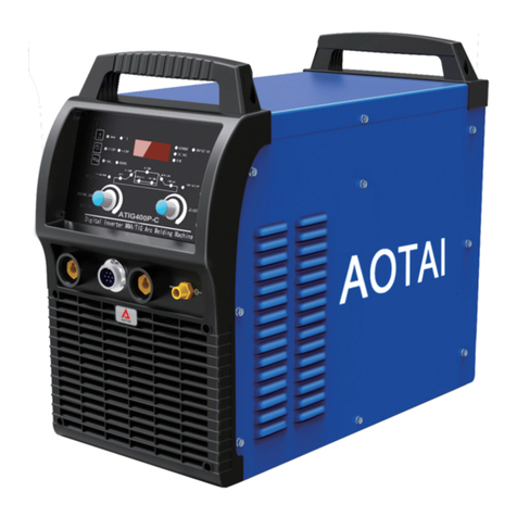
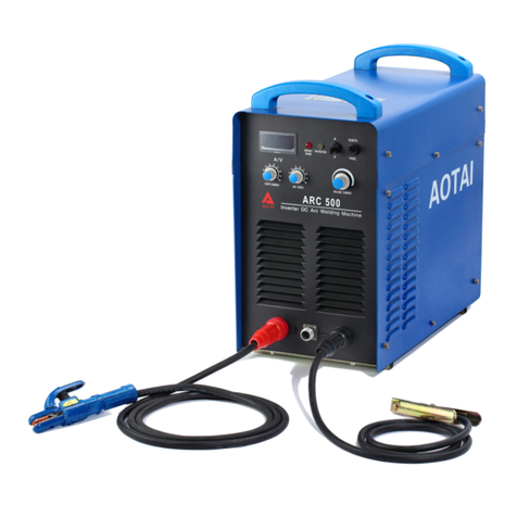
AOTAI Dura ARC160 User manual

Dear Customer
This instruction manual will help you get to know your new machine. Read the
manual carefully and you will soon be familiar with all the great features of your
new product. Meanwhile, please remember safety rules and operate as
instructed.
If you treat your product carefully, this definitely helps to prolong its enduring
quality and reliability-things which are both essential prerequisites for getting
outstanding results.
Production specification may change without advance notice.
The model you purchase is for:
Dura ARC200
Dura ARC200II
Please find corresponding models from the “Contents”.
Important:
Please take special note of safety rules and operate as instruction in case of
damage and serious injury.
Dura ARC160
Dura ARC160II
Dura ARC250
1

Safety Rules
“Danger” indicates an imminently hazardous situation which, if not avoided, will
result in death or serious injury.
“Warning!” indicates a possible hazardous situation which, if not avoided, could
result in death or serious injury. The possible hazards are explained in the text.
“Caution” indicates a possible hazardous situation which, if not avoided, may result
in slight or moderate injury.
“Note!” indicates a situation which implies a risk of impaired welding result and
damage to the equipment.
“Important!”indicates practical tips and other useful special-message. It is no signal
word for a harmful or dangerous situation.
Utilisation for intended purpose only.
defined by the “Intended purpose”.
Utilisation for any other purpose, or in any other manner, shall be deemed to be “not
in accordance with the intended purpose”. The manufacturer shall not be liable for
any damage resulting from such improper use.
The machine may only be used for jobs as
Safety signs.
be kept in legible condition, not removed, not be covered, pasted or painted cover.
All the safety instructions and danger warnings on the machine must
Safety inspection.
regular intervals.
The manufacturer also recommends every 3-6 months for regular maintenance of
power sources.
The owner/operator is obliged to perform safety inspection at
Electric shock can kill.
severe burns. The electrode and work circuit is electrically live whenever the output is
on. The input power circuit and machine internal circuits are also live when power is
on. In MIG/MAG welding, the wire, drive rollers, wire feed housing and all metal parts
touching the welding wire are electrically live. Incorrectly installed or improperly
grounded equipment is a hazard.
Do not touch live electrical parts of the welding circuit, electrodes and wires with your
bare skin or wet clothing.
The operator must wear dry hole-free insulating welding gloves and body protection
while performs the welding.
Insulate yourself from work and ground using dry insulating protection which is large
enough to prevent you full area of physical contact with the work or ground.
Connect the primary input cable according to rules. Disconnect input power or stop
machine before installing or maintenance.
If welding must be performed under electrically hazardous conditions as follow: in
damp locations or wearing wet clothing; on metal structures such as floors, gratings,
or scaffolds; when in cramped positions such as sitting, kneeling, or lying; or in
Touching live electrical parts can cause fatal shocks or
2

occasion when there is a high risk of unavoidable or accidental contact with the work
piece or ground. Must use additional safety precautions: semiautomatic DC constant
voltage (wire) welder, DC manual (Stick) welder and AC welder with reduced open-
load voltage.
Maintain the electrode holder, ground clamp, welding cable and welding machine in
good, safe operating condition. Replace damaged part immediately.
Electric and magnetic fields (EMF) may be dangerous.
interference is found to be occurring, the operator is obliged to examine any possible
electromagnetic problems that may occur on equipment as follow:
- Minas, signal and data-transmission leads
- IT and telecoms equipment
- Measurement and calibration devices
- Wearers of pacemakers
Measures for minimizing or preventing EMC problems:
- Mains supply
If electromagnetic interference still occurs, despite the fact that the mains connection
in accordance with the regulations, take additional measures
- Welding cables
Keep these as short as possible.
Connect the work cable to the work piece as close as possible to the area being
welded.
Lay them well away from other cables.
Do not place your body between your electrode and work cables.
- Equipotential bonding
- Workpiece grounding (earthing)
- Shielding
Shield the entire welding equipment and other equipment nearby.
If electromagnetic
ARC rays can burn.
Wear an approved welding helmet or suitable clothing made from durable
flame-resistant material (leather, heavy cotton, or wool) to protect your
eyes and skin from arc rays and sparks when welding or watching.
Use protective screens or barriers to protect other nearby personnel with
suitable, non-flammable screening and/or warn them not to watch the arc
nor expose themselves to the arc rays or to hot spatter or material.
Visible and invisible rays can burn eyes and skin.
Fumes and gases can be dangerous.
breathing these fumes and gases can be hazardous to your health.
When welding, keep your head out of the fume. If inside, ventilate the area at the arc
to keep fumes and gases away from the breathing zone. If ventilation is not good,
wear an approved air-supplied respirator.
Work in a confined space only if it is well ventilated, or while wearing an air-supplied
respirator.
Welding fumes and gases can displace air and lower the oxygen level causing injury
or death. Always use enough ventilation, especially in confined areas, to insure
breathing air is safe.
Welding may produce fumes and gases,
3

Welding and cutting sparks can cause fire or explosion.
sure the electrode circuit is not touching the work or ground. Accidental contact can
cause sparks, explosion, overheating, or fire. Make sure the area is safe before doing
any welding.
Welding and cutting on closed containers, such as tanks, drums, or containers, can
cause them to blow up. Make sure proper steps have been taken.
When pressure gas is used at the work site, special precautions are required to
prevent hazardous situations.
Connect work cable to the work as close to the welding zone as practical to prevent
welding current from passing too long and creating fire hazards or overheat.
Wear oil-free protective garments such as leather gloves, heavy shirt, cuffless
trousers, high shoes, and a cap. Wear ear plugs when welding out of position or in
confined places. Always wear safety glasses with side shields when in a welding
area.
Be attention that welding sparks and hot materials from welding can easily go
through small cracks and openings to adjacent areas and start a fire. Remove fire
hazardous from the welding area, if not possible, cover them thoroughly. Do not weld
where flying sparks can strike flammable material and where the atmosphere may
contain flammable dust, gas, or liquid vapors (such as gasoline).
Protect yourself and others from flying sparks and hot metal. Remove any
combustibles from operator before perform any welding.
Keep a fire extinguisher readily available.
Empty containers, tanks, drums, or pipes which have combustibles before perform
welding.
Remove stick electrode from electrode holder or cut off welding wire at contact tip
when not in use.
Apply correct fuses or circuit breakers. Do not oversize or bypass them.
When not welding, make
Cylinder can explode if damaged.
pressure. If damaged, a cylinder can explode. Since gas cylinders are normally part
of the welding process, be sure to treat them carefully.
Cylinders should be located away from areas where they may be struck or subjected
to physical damage. Use proper equipment, procedures, and sufficient number of
persons to lift and move cylinders.
Always install cylinders in an upright position by securing to a stationary support or
cylinder rack to prevent falling over or tipping.
Keep a safe distance from arc welding or cutting operations and any other source of
heat, sparks, or flame.
No touching cylinder by welding electrode, electrode holder or any other electrically
“hot” parts. Do not drape welding cables or welding torches over a gas cylinder.
Use only correct compressed gas cylinders, regulators, hoses, and fittings designed
for the process used; maintain them and associated parts in good condition.
Use only compressed gas cylinders containing the correct shielding gas for the
properly operating regulators designed for the gas and pressure used. All hoses,
Pressure gas cylinders contain gas under high
4

fittings, etc. should be suitable for the application and maintained in good condition.
Open the cylinder valve slowly and keep your head and face away from the cylinder
valve outlet.
Valve protection caps should be kept in place over valve expect when the cylinder is
in use or connected for use.
Hot parts can burn.
Ensure equipment is cooled down before perform any work.
If touching hot parts is needed, use proper tools and/or wear heavy, insulated
welding gloves and clothing to prevent burns.
Do not touch hot parts with bare hand or skin.
Flying metal or dirt can injure eyes.
grinding can cause sparks and flying metal. It can hurt your eyes.
Remember wear appropriate safety glasses with side shields when in welding zone,
even under your welding helmet.
When welding, chipping, wire brushing, and
Noise can damage hearing.
hearing.
Remember wear approved ear protection to protect ears if noise level is high.
Noise from some processes or equipment can damage
Moving parts can injure.
Stay away from pinch points such as drive rolls.
Keep all doors, panels, covers, and guards closed and securely in place.
Have only qualified persons remove doors, panels, covers, or guards for servicing
and maintenance.
Reinstall doors, panels, covers, or guards when servicing and maintenance is
finished and before reconnecting input power.
Stay away from moving parts such as fans.
Overuse can cause overheating.
reduce duty cycle before starting to weld again.
Allow cooling period.
Do not block or filter airflow to unit.
Use machine follow duty cycle. Reduce current or
Safety markings.
Low-Voltage and Electromagnetic Compatibility Guideline (e.g. relevant product
standards according to EN 60 974).
Equipment with CCC markings meets the requirements of implementations rules for
China compulsory certification.
Equipment with CE-markings fulfils the basic requirements of the
5

Contents
1-GENERAL REMARKS
1-1 Power source features
1-2 Functional principle
1-3 Output characteristics
1-4 Duty cycle
1-5 Applications
2-BEFORE COMMISSIONING
2-1 Utilization for intended purpose only
2-2 Machines set-up regulations
2-3
2-4
3-DURA ARC160/160II/200/ 250
3-1 System components
3-2 Standard equipments for welding
3-3 Control panel
3-4 Interface
3-5 Rear panel
3-6 Installation and operation
3-7 Technical data
3-8 Main components
3-9 Disassembly and reassembly
4-TROUBLE SHOOTING
5-CARE AND MAINTENANCE
6-BASIC WELDING
6-1 TIG welding
6-2 ( ) welding
Power source connection
Welding cables instruction
200II/
TECHNIQUE
technique
SMAW STICK technique
1
6
6
6
6
7
7
8
8
8
8
8
9
9
9
9
10
11
11
16
16
17
21
22
23
23
26

1-GENERAL REMARKS
1-1 Power source features
SMAWDura ARC160/160II/200/250/200II welding machine is suitable for DC , simple TIG
process, which can weld carbon steel, stainless steel, copper, titanium, etc. Because of the
ideal static characteristic and dynamic characteristics, machines highlights are as follows:
- Single phase 230V power supply, portable design
- Leading IGBT tube technology
- Rapid adjustment adapting to changes in the load, stable arc length, excellent
constant-current characteristics
- Low spatter
- Easily arc ignition, anti-stick features
- High penetration power, pretty weld formation
- Reliable and durable with patented technology
1-2 Functional principle
The schematic diagram is as shown in Fig. 1-2-1:
AC 230V
50/60Hz 1-phase
rectifier HF inverter HF
transformer
Rectifier
&filter
Output
Control
circuit
Fig. 1-2-1: Schematic Diagram
This series welding machine applies HF inverter technology. 1- phase 230V, 50/60Hz input
volt is rectified by rectifier, inverted into HF AC, reduced by HF transformer, rectified by HF
rectifier, then output DC power suitable for welding. After this process, the welder’s
dynamically responsive speed has been greatly increased, so the welder size and weight are
reduced noticeably.
Power source enjoy sound anti-fluctuating ability and high-quality performance during external
condition changes (such as power grid voltage fluctuation, fast distance welding with long
welding cable). Easy to arc start, stable arc length, pretty weld formation and capability of
continuous adjusting the welding current.
1-3 Output characteristics
The output characteristic is droop characteristic, which is suitable for Stick process.
6

1-4 Duty cycle
Duty cycle is percentage of 10 minutes that unit can weld at rated load without overheating. If
unit overheats, thermostat(s) close, output stops, and cooling fan runs. Wait twenty minutes
for unit to cool. Reduce amperage or duty cycle before welding.
NOTE! Exceeding duty cycle can damage unit and void warranty.
Fig. 1-4-1: Duty Cycle (at 40 C)
1-5 Applications
The ARC series can weld most of the metal materials absolutely including the welding
of carbon steel, stainless steel, etc. The recommend areas of use as follows:
- Boiler and pressure vessel fabrication
- Chemical industry
- Power generation and process
- Shipbuilding
- Automotive manufacture
- Machinery manufacturing
- Pipeline industry (Dura ARC160II/200II)
0
15
20
59
U(V)
I (A)
U=20+0.04I
I min I max
Fig. 1-3-1: Output Characteristics
7
1 0 20 30 40 5 0 6 0 7 0 8 0 9 0 1 0 0
WELD AMPERES
0
% DUTY C YCLE
2 0 0
250
300
3 5
1 0 0
160
1 1 2
118
1 2 4
D u r a A R C 2 0 0 / 2 0 0Ⅱ
D u r a A R C 2 5 0
D u r a A R C 1 6 0 / 1 6 0Ⅱ

2 - BEFORE COMMISSIONING
Warning! Operating the equipment incorrectly can cause serious injury and damage.
Do not use the machine until you have read "Safety rules".
2-1 Utilization for intended purpose only
The power source may only be used for SMAW and Simple TIG welding. Utilization for
any other purpose, or in any other manner, shall be deemed to be "not in accordance
with the intended purpose". The manufacturer shall not be liable for any damage
resulting from such improper use.
Please perform the inspection and maintenance work in accordance with all the
instructions given in this manual.
2-2 Machines set-up regulations
The power source is tested to "Degree of protection IP23S", However, direct wetting
should be avoided.
Warning! A machine that topples over or falls from its stand can easily kill someone.
Place machine on an even, firm floor in such a way that it stands firmly.
The venting duct is a very important safety feature. When choosing the machine location,
make sure it is possible for the cooling air to enter and exit unhindered through the louvers on
the front and back of machine. Any electroconductive metallic dust from e.g. grinding-work
must not be allowed to get sucked into the machine.
2-3 Power source connection
- The power source is designed to run on the mains voltage given on the respective rating
plates.
- The mains cables and plugs must be mounted in accordance with the relevant technical
standard.
- The power supply socket come with power source is designed to use strictly according to
the marked voltage class.
Note! Inadequately dimensioned electrical installations can lead to protection failed
or partially failed. The mains plug and socket, and its fuse protection, must be
dimensioned in accordance with local power supply.
8
2-4 Welding cables instruction
- The cross section area of welding cable must meet the requirements of welding machine
output current value.
- When the extension cable is being used, please appropriately increase the cross-sectional
area of the cable.

3–DURA ARC160/160II/200/ 250200II/
3-1 System components
Welding cable
Ground cable
Power source
3-2 Basic equipments for welding
- Power source
- Ground cable
- Electrode holder
- Electrode
9
Fig. 3-1-1: System components
3-3 Control panel
Note! Your machine has certain functions that are not in accordance with this
operating manual, or vice versa. Also, certain illustrations may be slightly different
from the actual controls on your machine. However, these controls function in exactly
the same way.
Warning! Operating the equipment incorrectly can cause serious injury and damage.
Do not use the functions described here until you have read and completely
understood this operating manual.

WELDING CURRENT(A)
12
4
5
3
1. Protection on LED
Yellow color, which will light off if the machine operates properly; lights up if the power source
overheats or some other fault, machine will stop working automatically, keep the machine
power on and fan running until the overheat indicator lights off, then wait 20 minutes before
start welding.
2. “Amp” LCD
When power on, LCD displays the welding current; and the welding current value can be
adjusted by “welding current” regulation knob.
3. Welding current regulation knob
Used for adjusting current value. Adjust welding current according to work piece thickness,
groove shapes, welding position, electrode diameter, etc. Welding current decides welding
seam penetration and wire molten speed.
4. Process selection switch
Used for select the desired welding mode, two modes are available, DC Stick, simple TIG.
5. Striking current “ON/OFF” selection switch
Striking current is “ON”, which is used mostly in DC processSMAW
Striking current is “OFF”, which is recommend for thin sheet welding to avoid work
piece burn through.
10
Fig. 3-3-1: Control panel
3-4 Interface
Fig. 3-4-1: Output interface
CURRENT

6. Welding cable quick socket (+)
For basic electrode: used for connecting the electrode holder.
For cellulose electrode & acid electrode: used for connecting the work piece. (For Dura
ARC160II/200II)
In simple - TIG process: used for connecting the work piece.
7.Welding cable quick socket (-)
For basic electrode: used for connecting the work piece.
For cellulose electrode & acid electrode: used for connecting the electrode holder. (For Dura
ARC 200II)
In simple– TIG process: used for connecting TIG torch.
160II/
1. Power switch
Switch for 230V single-phase AC power.
Turn on this switch (on the position: “ON”), then the front panel digital meter lights up, and the
fan runs.
2. Power supply cable
The mixed-colored wire must be firmly grounded; the rest wires connect to 1- phase AC 230V
~50/60Hz power supply.
3. Cooling fan
Cool down the hot components inside welding machine.
Fig. 3-5-1: Rear panel
3-5 Rear panel
23
1
11
3-6 Installation and operation
Warning! If the machine is plugged into the mains supply during installation, there is
a high risk of very serious injury and damage. Only carry out work on the machine
when you have read "Safety rules" and when
- the mains switch is in the "OFF" position;
- the machine is unplugged from the mains;
Installation of power supply cable
Specifications of mains input are shown in Table 3-6-1:

Table 3-6-1:Specifications of mains input
Model Dura ARC200/200II Dura ARC250
1- phase AC230V±15%, 50/60Hz
Power supply
Electricity grid min. capacity ( )KVA
Cable size
( )mm
Fuse
Circuit breaker
Input cable
Output cable
Protective GND wire
Input
protection
(A)
25
16
≥2.5
70
60
12 16
≥2.5
The connection between input cable and distribution box (Fig. 3-6-1)
Warning!
- Never perform hot-line work!
- Electric connection should be done by professional electrician!
- Two machines should not be connected to the same one circuit breaker!
- Check the input voltage, circuit breaker, input cable in accordance with Table 3-6-1.
Specifications of mains input
Fig. 3-6-1: Connection between input cable & distribution box
Power socket and using region
Table 3-6-2: Power socket selection
A: 2-plug flat type B: 2-plug flat + GND
round hole type
L
N
C: 2-plug flat 8 type
12
E
NL
E
L
N
GND/PE earth
ground
AC230V±15%
GND
Yellow-green mixed wire is used
for grounding! Not connected to
zero wire! Please connect
according to picture or other
correct way. Please disconnect
mains power when connecting!
Dura ARC160/160II
9
16

E: 2-plug round (4.0mm) type F: 2-plug round (4.0mm) type
G: 2-plug round + GND
round hole type H: 2-plug round + bayonet type
L
N
D: 3-plug flat 8 type
I: 3-pin flat type
K: 3-pin round type M: Switzerland type N: Italy type
O: Denmark type P: Israel type
Power socket selection
Table 3-6-3: Using region selection
Country Type Country Type
Asian-Pacific region
Hong-Kong
Vietnam
Malaysia
Indonesia
Australia
Japan
I
A, B, E, G
I
E, G
C, D
A, B
Macau
Thailand
Singapore
India
New-Zealand
Korea
E, G
A, B
I
I, K
C, D
E, G
13

Country Type Country Type
Saudi Arabia
Dubai
A, B, I
G
Iran E
Middle East region
Europe region
Italy
Poland
Greece
E, N
E, F, G
E, F, G
Austria
Hungary
Belgium
E, F, G
F, G
E, F, G
Netherlands
France
Spain
E, F, G
E, F, G
E, F, G
United Kingdom
Switzerland
German
I
E, M
E, F, G
Finland
Russia
E, F, G
E, F, G
Denmark
Turkey
E, F, G, O
E, F
America region
United States
Mexico
Venezuela
Peru
Chile
A, B
A, B
A, B
A, B, E
E, N
Canada
Columbia
Brazil
Argentina
Uruguay
A, B
A, B
A, B, E
C, D
E
Africa region
Rep. South Africa K
Using region selection
Stick welding
Stick welding with basic electrode: E7016/E7018
Warning! Operating the machine incorrectly can cause serious injury and damage.
Do not use the machine until you have read the following:
- Safety rules
- Before putting the power source into service
Warning! If the machine is plugged into the mains supply and the mains switch is in
“ON” position during preparation, there is a high risk of very serious injury and
damage. Only carry out preparation when the machine is unplugged from the mains
and mains switch is OFF.
1. Plug the ground cable into the output socket (-) and fasten it;
2. With the other end of ground cable, establish a connection to the work piece;
14

3. Plug the welding cable into the output socket (+) and fasten it;
4. Connect with single phase 230V power supply, and put the circuit breaker in ON position;
5. Switch on the mains switch;
6. Turn “Welding Current” knob to adjust the welding current according to the size of electrode;
7. Start welding.
Stick welding with cellulose electrode E6010 & acid electrode E6013
1. Plug the ground cable into the output socket (+) and fasten it;
2. With the other end of ground cable, establish a connection to the work piece;
3. Plug the welding cable into the output socket (-) and fasten it;
4. Connect with single phase 230V power supply, and put the circuit breaker in ON position;
5. Switch on the mains switch;
6. Turn “Welding Current” knob to adjust the welding current according to the size of electrode;
7. Start welding;
TIG welding
Shielding gas regulator operating instructions
Warning! The inert gas can be hazardous to your health. Work in a place only if it is
well ventilated. Please do not use the shielding-gas cylinder until you have
completely read and followed all the instructions about shielding-gas cylinder and
accessories.
1. Take the protective cap off the shielding-gas cylinder;
2. Briefly open the shielding-gas cylinder valve anticlockwise to blow off any dust and dirt;
3. Check the tightness of pressure regulator;
4. Screw the pressure regulator onto the gas cylinder and tighten it;
5. Place the shielding-gas cylinder on the solid, level surface or use cylinder bracket to
prevent from toppling over;
The connection and operation for gas-cooling TIG welding
1. Plug the ground cable into the output socket (+) and fasten it;
2. With the other end of ground cable, establish a connection to the work piece;
3. Screw the pressure regulator onto the gas cylinder and tighten it;
4. Plug the gas hose plug on the end of torch into the gas outlet of pressure regulator and
screw it;
5. Connect with single phase 230V power supply, and put the circuit breaker in ON position;
6. Switch on the mains switch;
7. Select simple TIG mode with the “SMAW / TIG” selection control switch;
Note! "SMAW" welding process should not be selected when the TIG process has
been selected. The "SMAW" is activated if selecting "SMAW".
8. Turn knob to adjust the welding current;
9. Select with “striking current ON/OFF” selection switch;
10. Open the pressure regulator valve and set the desired gas flow rate on the pressure
regulator;
11. Establish electric arc successfully between the tungsten electrode and the work piece in
contact way, and then draw back the electric arc to start welding;
12. Pull out electric arc after finishing welding;
13. Close cylinder valve after seconds;
15
Welding Current

3-7 Technical data
Table 3-7-1: Technical data
200/200II 160/160II 250
IGBT inveter
Model
Control type
Rated input voltage (V)
Input voltage frequency (Hz)
1-phase AC230±15%
50/60
Rated input power (KVA)
Rated input current (A)
Rated duty cycle (%)(@40℃)
Rated output open-load voltage (V)
Ouput welding current (A)
Arc force current in (A)
Hot start current in (A)
Protection class
SMAW
SMAW
7
31.8
35
9.4
43.5
20
59
20 ~ 200 20 ~ 250
50
70
IP23S
Insulation class
COSφ
Efficiency (%)
Cooling style
Dimension (W×D×H) (mm )
Weight (Kg)
F
0.98
≥80
Forced air cooling
389×155×299
7.3
Technical data
3-8 Main components
No. Tab Item Stock No. Quantity Remark
16
Table 3-8-1:Main components
59 80
160(II)/
250
250
200(II)
160(II)/200(II)
1
1
2
2
745002-00019
745011-00068
735004-00005
735004-00006
Circuit breaker
Single phase rectifier bridge
SF3
TB301~
TB302
1
2
3RE301 Varistor 720021-00020 1All
5.3
23.4
60
59
20 ~ 160
80
3

3-9 Disassembly and reassembly
3.9.1 Disassembly and reassembly of unit
Main components
17
No. Tab Item Stock No. Quantity Remark
RD301~
RD304 720021-00031 4250
Thermistor
CE202~
CE204
720022-00013 4 160(II)/200(II)
Aluminum electrolytic
capacitor 722004-00105 3 ALL
KF211~
KF242
735003-00011
735003-00013
8 160/200
8 160II/ 250200II/
IGBT tube
4
5
6
T1 763001-00207 1 ALL
Power transformer
7
8T251 Main transformer
9 Diode
RB251~
RB258
730001-00027 8
730001-00041 8 250
160(II)/200(II)
10 BB1 745009-00012 1 ALL
Temperature relay
11 PG1 755001-00028 1 ALL
12 FA1 Fuse 745007-00045 1 ALL
13 FA2~FA3 Fuse 720022-00049 2 ALL
14 BE401 753001-00074 1 ALL
15 GQ1 Fan 746002-00025 1 ALL
Digital display meter
Current transformer
210580-00620 1 00
210580-00649 1 250
-- 1 160II/200II
210310-00094 1 160/200
210310-00103 1 250
-- 1 160II/200II
160/2
16 A1 Main board
17 A2 Drive board
18 A3 Display board 220503-00113 1 ALL
19 PH1 Protection lamp 715002-00014 1 ALL
763002-00022 1 160/200/250
-- 1 160II/200II
20 RW1 Potentiometer 720031-00128 1 ALL
21 SF1 Toggle switch 745003-00013 1 ALL
22 SF2 Toggle switch 745003-00034 1 ALL

Fig. 3-9-1: Disassembly and reassembly of unit
Table 3-9-1: Key components
No. Stock No. Description Quantity
Plastic Front Panel
Main Case
Welding Machine Handle
Plastic Rear Panel
Rocker Switch
Fan
1
2
3
4
5
6
7
8
9
262005-00943
779002-00009
779002-00501
262047-00091
766003-02141
262011-00639
745002-00019
779002-00502
746002-00025
GB_CROSS_COUNTERSUNK_SCREWS M4X12
Cross Recess Pan Head Screw
M4×10 Black (three combinations)
Cross Recess Pan Head Screw
M5×16 Black (three combinations)
1
8
14
1
1
1
1
4
1
1
2
3
4
5
67
8
9
10
11
12
13
14 15
18 19
1617
10
11
12
13
14
15
16
210340-00637
263065-00397
740002-00080
--
720031-00105
720031-00128
715002-00014
Radiator Components
Bottom Board
Quick Socket Copper Core
Knob
Potentiometer Knob
Potentiometer
LED
1
1
2
2
1
1
1
18

LED Base
Digital Displayer
Control Board
740008-00005
755001-00028
262035-00296
1
1
1
3.9.2 Disassembly and reassembly of radiator
Fig. 3-9-2: Disassembly and reassembly of radiator
1
2
3
4
5 6 7
8 9
13 12 11
14
15
17
18
19
20
21
22 23
24
25
26
27
10
16
17
18
19
Key components
Table 3-9-2:Key components
No. Stock No. Description Quantity
1
2
3
4
5
6
7
8
9
10
11
12
763001-00207
775001-00037
775001-00038
779002-00009
779002-00281
779007-00017
779007-00006
210310-00094
210580-00620
763002-00022
779002-00082
779007-00008
Power Transformer
Power Transformer Fixed Plate 1
Power Transformer Fixed Plate 2
GB_CROSS_COUNTERSUNK_SCREWS M4X12
Flat Washer Ф4
Spring Washer Ф4
Drive Board Assembly
Main Board Assembly
Main Transformer
GB_CROSS_HEX_SCREWS M6X12
Spring Washer Ф6
1
1
1
8
19
2
2
1
1
1
5
5
19
Cross Recess Pan Head Screw
M3×10 (three combinations)
This manual suits for next models
4
Table of contents
Other AOTAI Welding System manuals
Popular Welding System manuals by other brands

GWS
GWS TIGARC 200DC TIG Instructional manual

SFS intec
SFS intec isoweld 3000 Series operating instructions

Linz
Linz E1W10 150AC Operating and maintenance instruction

Amada
Amada ML-2450A-CE Operation manual

Miller
Miller DIVERSION 165 And owner's manual

Tokentools
Tokentools Multi-process 200 instruction manual

Lincoln Electric
Lincoln Electric ACTIV8 Operator's manual

ArcOne
ArcOne Inverter Power Sources User instruction manual

Nupi
Nupi Elofit Smartflex quick guide

Air Liquide
Air Liquide SAFMIG 280 BL Safety instruction for use and maintenance

Bernard
Bernard T-Gun 450 owner's manual

Lincoln Electric
Lincoln Electric MAXsa 29 WIRE DRIVE Operator's manual