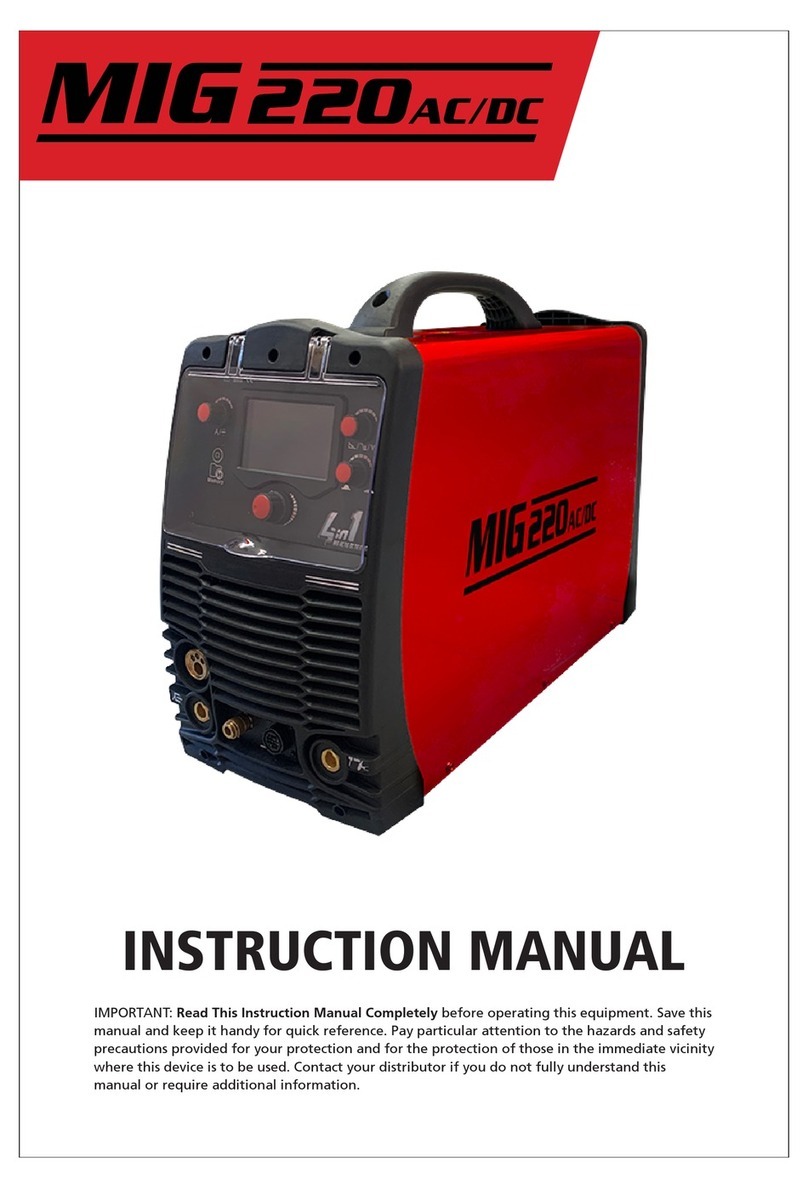
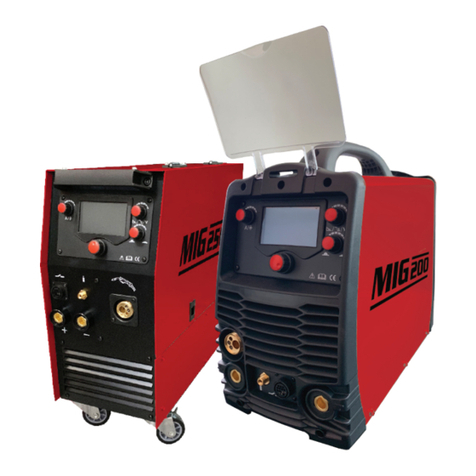
GWS TIGARC 200DC TIG Operating and maintenance manual

INSTRUCTIONAL MANUAL

1
Contents
Features
1.0 Recommended Safety Precautions ........................ 2
1.1 Health Hazard Information.................................... 2
1.2 Personal Protection ................................................ 2
1.3 Electric Shock .......................................................... 3
1.4 User Responsibilities .............................................. 3
• DC TIG, MMA
• IGBT technology, MCU control system, Easy HF ignition
• Outstanding performance on aluminium alloys,
carbon steel, stainless steel & titanium
• Low current consumption
• Power Factor Correction (PFC)
2.0 Gas Tungsten Arc Welding (GTAW/TIG) ................ 4
2.1 Introduction ............................................................ 4
2.2 Polarity Variations .................................................. 4
2.3 Shielding Gas Selection .......................................... 6
2.4 Consumable Selection ............................................ 7
2.5 Welding Techniques ............................................... 8
2.6 Torch Movement During Welding ......................... 8
2.7 Torch Positioning ................................................... 8
2.8 Non Consumable Tungstens .................................. 9
2.9 Joint Preparation .................................................. 12
2.10Troubleshooting ................................................... 14
3.0 TIG Welding Material Reference ......................... 16
3.1 Application Summary ........................................... 16
3.2 C-Mn Steel ............................................................. 17
3.3 Alloyed Steel ......................................................... 18
3.4 Stainless Steel........................................................ 19
3.5 Aluminium ............................................................ 19
3.6 Balanced Square wave ......................................... 20
3.7 Copper and Copper Alloys ................................... 20
6.0 Warranty Information .......................................... 25
6.1 Terms of Warranty ................................................ 25
6.2 Limitations on Warranty ...................................... 25
7.0 Recommended Safety Guidelines ........................ 26
8.0 Machine Hazards .................................................. 26
5.0 Technical Specifications ........................................ 25
4.0 Getting Started With Your TIGARC 200DC ........... 21
4.1 Power .................................................................... 21
4.2 Shielding Gas ........................................................ 21
4.3 TIG Torch Connection ........................................... 21
4.4 MMA Operation ................................................... 21
4.5 Panel, Functions & Features Guide ..................... 22
4.6 DC TIG Welding .................................................... 23
4.7 DC Pulse TIG Welding ........................................... 23
4.8 AC TIG Welding .................................................... 24
PLEASE NOTE that under no circumstances should your
TIGARC 200DC be altered or changed in any way from
standard factory configuration. Doing so, will void the
machine warranty.

1.1 Health Hazard Information
2
1.0 Recommended Safety Precautions
The welding process can cause a variety of possible hazards
for the operator and those in close proximity. All
appropriate safety precautions should be made to prevent
harm and injury. Although these precautions are not all
inclusive, the following considerations should be followed
for most welding applications. As always, electrical
equipment should be used in accordance with the
manufacturer’s recommendations.
Eyes
The welding process produces ultraviolet rays that can cause
permanent eye damage. In addition, welding fumes may
also cause serious eye irritation.
Skin
Arc rays are dangerous to uncovered skin and will cause
burning of the skin.
Inhalation
Welding fumes and gases are dangerous to both operator
and to those in close proximity. Fumes may cause a number
of respiratory ailments. Excessive exposure may cause
nausea, dizziness, dryness, irritation of nose, throat & lungs
or even permanent lung damage.
1.2 Personal Protection
Respiratory
Welding in confined areas should be carried out with the
aid of a fume respirator or air supplied respirator as per
AS/NZS 1715 and AS/NZS 1716 Standards.
• Ensure proper ventilation at all times
• Keep your head out of the fumes emitted by the arc
• Fumes from the welding of some metals could have an
adverse effect on your health. DO NOT breathe them in.
If you are welding on materials such as stainless steel,
nickel, alloys or galvanised steel, additional
precautions are necessary.
• Wear a respirator when natural or forced ventilation
is not sufficient.
Eye Protection
A welding helmet fitted with the appropriate welding shade
lens for the welding operation must be worn at all times
when welding. The welding arc and the reflecting arc flash
emits ultraviolet and infrared rays. Protective welding
screening and eye protection should be provided for others
working in the area.
Clothing
Suitable clothing must be worn to prevent excessive skin
exposure to UV radiation, sparks and molten metal. Flame-
proof, loose fitting cotton clothing buttoned to the neck,
protective leather gloves, spats, apron and steel toe safety
boots are also highly recommended. In addition, use a
helmet with the recommended shade lens for amperage
listed in the shade chart below.
Ten Points about Cylinder Safety
1) Read labels and Material Safety Data Sheet (MSDS)
before use
2) Store upright and use in well ventilated, secure areas
away from pedestrian or vehicle thoroughfare
3) Guard cylinders against being knocked violently or
being allowed to fall
4) Wear safety shoes, glasses and gloves when handling
and connecting cylinders
5) Always move cylinders securely with an appropriate
trolley. Take care not to turn the valve on when moving
a cylinder
Cylinder Safety
Back view of typical
cylinder valve
Operator wearing personal
protection equipment (PPE) in safe position
Less than 150 amps
150 to 250 amps
250 to 300
300 to 350
Over 350 amps
Use one shade darker for aluminium welding
Shade 9
Shade 10
Shade 11/12
Shade 13
Shade 14

3
When operating the cylinder valve:
• Open by hand turning the valve hand wheel
anti-clockwise using no more than reasonable force
• Ensure that no gas is leaking from the cylinder valve
connection or the system to which the cylinder is
connected. DO NOT use ammonia-based leak detection
fluid as this can damage the valve. Approved leak
detection fluid, can be obtained from your gas provider
• When cylinder is empty, close the valve by turning
the valve hand wheel in a clockwise direction using no
more than reasonable force
Ten Points about Cylinder Safety (continued)
6) Keep in a cool, well ventilated area, away from heat
sources, of ignition and combustible materials,
especially flammable gases
7) Store full and empty cylinders separately
8) Keep ammonia-based leak detection solutions, oil and
grease away from cylinders and valves
9) Never use excessive force when opening or closing valves
10) Don’t repaint or disguise markings or damage.
If damaged, return cylinders immediately
Cylinder Valve Safety
When working with cylinders or operating cylinder valves,
always wear appropriate protective clothing – gloves, boots
and safety glasses. When moving cylinders, ensure that the
valve is not accidentally opened in transit.
Before operating a cylinder valve:
• Ensure that the system you are connecting the cylinder
into is suitable for the gas and pressure involved
• Ensure that hoses are securely connected to the cylinder
valve and system. A hose, for example, can potentially flail
about dangerously if it is not restrained at both ends
and accidentally pressurised
• Stand to the side of the cylinder so that neither you nor
anyone else is in line with the back of the cylinder valve.
This is in case a back-plug is loose or a bursting disc vents.
The correct stance is shown in the “Cylinder Safety”
diagram previously in this section
1.3 Electrical Shock
• Never touch ‘live’ electrical parts
• Earth clamp all work materials
• Never work in wet or damp environments
Avoid electric shock by:
• Wearing dry, insulated boots
• Using dry, leather gloves
• Never changing electrodes with bare hands or wet gloves
• Never cool electrode holders in water
• Work on a dry, insulated floor where possible
• Never hold the electrode or holder under your arm
1.4 User Responsibilities
• Read the Instructional Manual prior to using your
TIGARC 200DC
• Unauthorised repairs to this equipment may endanger
the technician and operator and will void your Warranty.
Only qualified personnel should perform repairs
• Always disconnect mains power before investigating
equipment malfunctions
• Replace broken, damaged, missing or worn parts & hoses
immediately.
• Equipment should be cleaned & serviced periodically

2.0 Gas Tungsten Arc Welding (GTAW/TIG)
4
2.1 Introduction
Either direct or alternating current may be used in the
welding process. For DC operation the tungsten may be
connected to either output terminal, however is most
commonly connected to the negative terminal. The output
characteristics of the power source will have an effect on
both the quality and speed of the weld.
Shielding gas is directed into the arc area through the
welding torch. A collet body inside the torch distributes the
shielding gas evenly over the weld area. In the torch the
welding current is transferred to the tungsten electrode
from the copper conductor.
2.2 Polarity Variations
DCEN
When direct-current electrode-negative (straight polarity)
is used:
• Electrons strike the part being welded at a high speed
• Intense heat on the base metal is produced
• The base metal melts very quickly
• Ions from the inert gas are directed towards the negative
electrode at a relatively slow rate
The increased amperage provides:
• Deeper penetration
• Increased welding speed
• A narrower, deeper, weld bead
• Better arc control
Use of DCEN
For a given diameter of tungsten electrodes, higher amper-
age can be used with straight polarity. Straight polarity is
used mainly for welding:
• Carbon steels
• Stainless steels
• Copper alloys
• Titanium
Sheilding gas
Arc
TIG filler rod
Weld pool
Collet body
Tungsten electrode
Workpiece

DCEP
DCEP (reverse polarity) is different from DCEN in the
following ways:
• High heat is produced on the electrode rather than on
the base metal
• The heat melts the tungsten electrode tip
• The base metal remains relatively cool compared to
straight polarity
• Relatively shallow penetration is obtained
Use of DCEP
• Intense heat means a larger diameter of electrode must
be used with DCEP.
• Maximum welding amperage should be relatively high
5

6
2.3 Shielding Gas Selection
Aluminium bronze
Brass
Cobalt-based alloys
Copper-nickel (Monel)
Deoxised copper
Nickel alloys (Inconel)
Steel
Magnesium alloys
Stainless steel
Titanium

7
2.4 Consumable Selection
Welding Wire
The following table includes the recommended welding consumable for the most commonly welded materials.
0.9 - 1.6
1.6 - 2.0
1.6 - 2.0
2.4
3.2

8
2.5 Welding Techniques
2.6 Torch Movement During Welding
2.7 Positioning Torch Tungsten for Various Weld Joints

9
Non Consumable Tungstens
Mild Steels,
Carbon Steels,
Alloy Steels,
Stainless Steels &
Titanium Alloys
DCEP
DCEN
100% He
DCEN
DCEN
100% He

10

11

2.6 Joint Preparation
12

13

14
Increase gas flow post time to approx. 1 sec per 10 amps
strike plate or use high frequency arc starter.
Filler material is oily, dusty or rusty

15
Use remote amperage or foot control to manually
down slope current
Lower the travel speed/increase amps
Preheat. Increase weld bead cross-section size.
Change weld bead contour. Use metal with fewer
alloy impurities & longer down slope
Change gas flow or gas lens parts
Reduce weld current and use arc length as short as
possible. Move influence.
Do not operate beyond rated capacity. Use water cooled
model. Do not bend rigid torches or overbend flexi torches

3.0 TIG Welding Material Reference
16
3.1 Application Summary
DCEN
DCEN
DCEN
DCEN
DCEN
ACEN
DCEN
ACEN

3.2 C-Mn Steel
17
TIG welding may be used for welding carbon steel but
because deposition rates are low, it is usually only used for
welding sheet and thin sections for high quality
applications, small components, and root passes of
multi-pass butt joints in plate and pipe.
Standard DC TIG equipment is normally suitable and DCEN
polarity is usually chosen to provide good workpiece
heating.
Only inert or reducing gases should be used for TIG welding
and pure argon is normally recommended as the shielding
gas for steel.
Filler rods are usually selected to match the chemical
composition and the mechanical properties of the parent
plate. The weldability of the steel may impose restrictions
on the choice of filler rod.
Steels with carbon contents above about 0.3%are harden-
able, and fast cooling will produce a hard HAZ and this is
liable to result in hydrogen cracking. This form of cracking
can be prevented by use of preheat and suitable welding
procedures.
2.4
2.4
2.4
2.4
2.4
2.4
2.4
25
30
50
80
20
40
80

3.3 Alloyed Steel
18
TIG welding may be used for welding alloyed steel but
because deposition rates are low, it is usually only used for
welding sheet and thin sections for high quality
applications, small components and root passes of multi-pass
butt joints in plate and pipe.
Standard DC TIG equipment is normally suitable and DCEN
polarity is usually chosen and provide good workpiece
heating. Tungsten electrodes with additions of thorium
oxide are used for welding steel and they give good arc
stability. Only inert or reducing gasses should be used for
TIG welding and pure argon is normally recommended as
the shielding gas for welding alloy steel.
Filler rods are usually selected to match the chemical
composition and the mechanical properties of the parent
plate. The weldability of the steel may impose restrictions
on the choice of filler rod.
Alloy steels with high carbon equivalents are hardenable
and fast cooling will produce a hard HAZ and this is liable to
result in hydrogen cracking. This form of cracking can be
prevented by preheating and other appropriate safeguards.
General Welding Parameters
1.6
1.6/2.4
1.6/2.4
2.4/3.2
2.4/3.2
2.4/3.2
2.4/3.2
2.4/3.2
1.0/1.2
1.6
1.6
1.6
1.6/2.4
2.4
2.4/3.2
3.2

19
3.4 Stainless Steel
TIG welding is often used for stainless steels, in particular,
thin sheet up to 5mm thick, where weld integrity and good
surface finish are critical. The process has a high degree of
controllability resulting in clean, smooth, high quality welds
with good penetration and strength with low defect rate.
Standard TIG equipment is suitable for stainless steel
welding using DCEN polarity. A thoriated tungsten electrode
is normally used, however due to health concerns, ceriated,
lanthanated or E3 electrodes may also be used. The filler rod
selection depends on the type of stainless base metal being
welded.
Shielding gas is conventionally pure argon, but other gases
are available that provide specific results. Other gasses
include argon/hydrogen, argon/helium &
argon/helium/hydrogen mixtures.
3.5 Aluminium (AC Welding Only)
TIG welding is widely used for welding aluminium,
particularly up to about 6mm thick.
TIG welding of aluminium can be carried out using alternat-
ing current (AC) or direct current electrode positive (DCEP).
AC is the most frequently used since with AC cleaning of the
oxide film occurs on the electrode positive cycle and heating
occurs on the electrode negative cycle. With aluminium, the
surface oxide film must be removed to allow full fusion to
take place and AC TIG does this efficiently allowing high
quality joints to be made. High purity argon or
argon/helium/hydrogen shielding gas mixtures may be used.
The AC output may be conventional sine wave or square
wave and many electronic power sources allow the AC
waveform to be adjusted. Some also offer the ability to
provide pre and post gas flow as well as slope-in and slope
out functions.
Aluminium Welding Parameters
This manual suits for next models
1
Table of contents
Other GWS Welding System manuals
Popular Welding System manuals by other brands

IMS
IMS SPOT 14500 TRAFO user manual

Welbach
Welbach OMEGA 500-2.0 user manual

Spartus
Spartus ProTIG 220P AC/DC user manual

Northern Industrial Tools
Northern Industrial Tools ARC 70 164620 Operator's manual

Paton
Paton STANDARDTIG-160 user manual

Parkside
Parkside PISG 80 A2 Assembly, operating and safety instructions, Translation of the original instructions