AP Diving RBV07 Series User manual

AP Diving Ltd. RBV07 Swivel Inflator Range Maintenance Manual
Page 1 of 50
RBV07
Swivel Inflator Range
Maintenance Manual
Version 0.95
April 2019
Written by Tino de Rijk

AP Diving Ltd. RBV07 Swivel Inflator Range Maintenance Manual
Page 2 of 50
Table of Contents
1. Introduction ........................................................................................... 4!
1.1 Functional description .................................................................................... 4!
1.2 Servicing ........................................................................................................ 4!
1.3 Warranty ......................................................................................................... 4!
1.4 Copyright and Applicable Law ........................................................................ 4!
3. RBV07 Swivel Inflator Range Exploded Diagrams and Parts Lists ..... 5!
3.1 RBV07(A) Single Swivel Inflator main assembly ............................................ 5!
3.2 RBV07(A)/DUAL Dual Swivel Inflator main assembly .................................... 6!
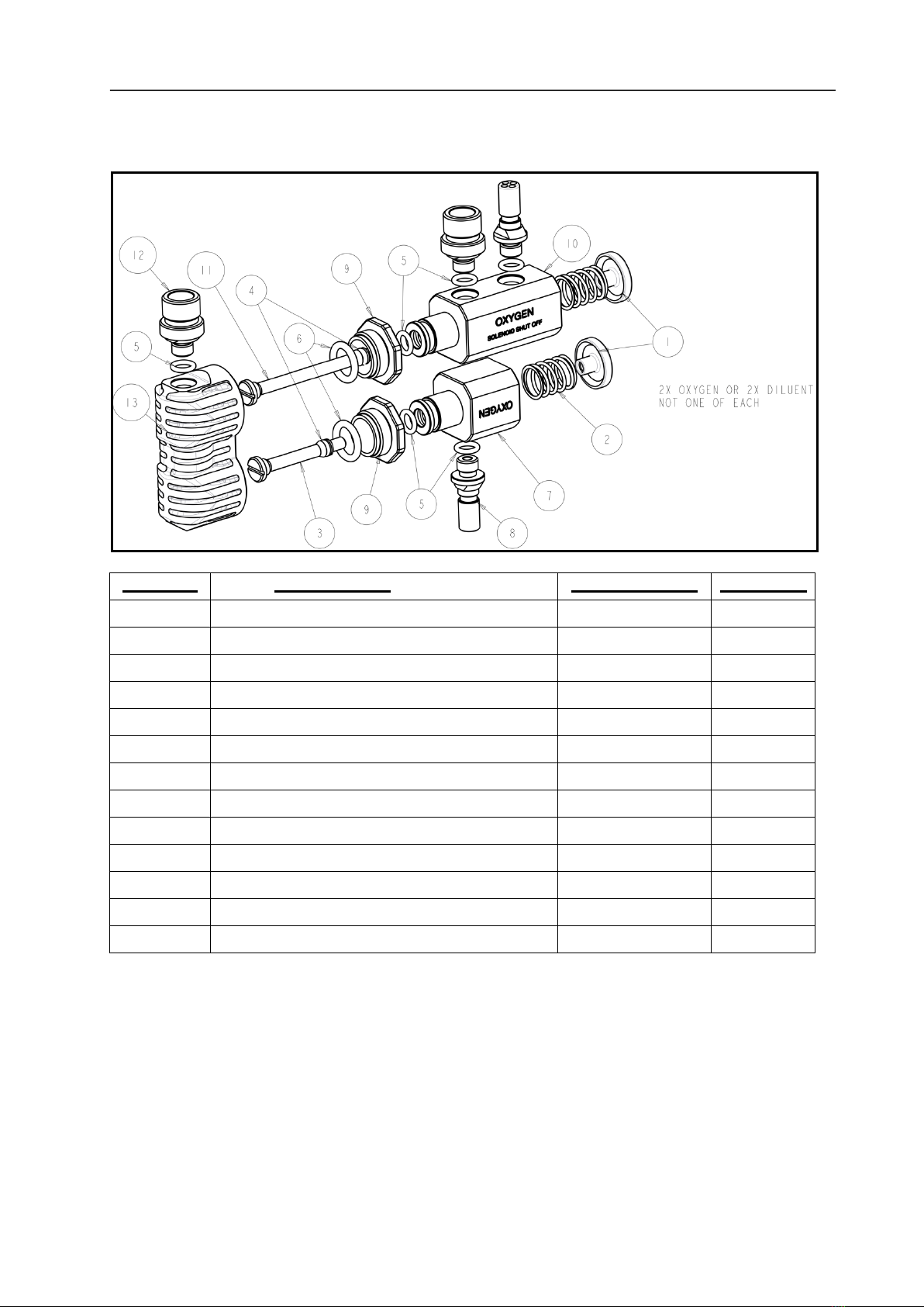
3.3 RBV07(A)/SO Single Swivel Inflator with Shutoff Valve main assembly ........ 7!
3.4 RBV07(A)/DUAL/SO Dual Swivel Inflator with Shutoff Valve main assembly 8!
3. General Information .............................................................................. 9!
3.1 Four versions ................................................................................................. 9!
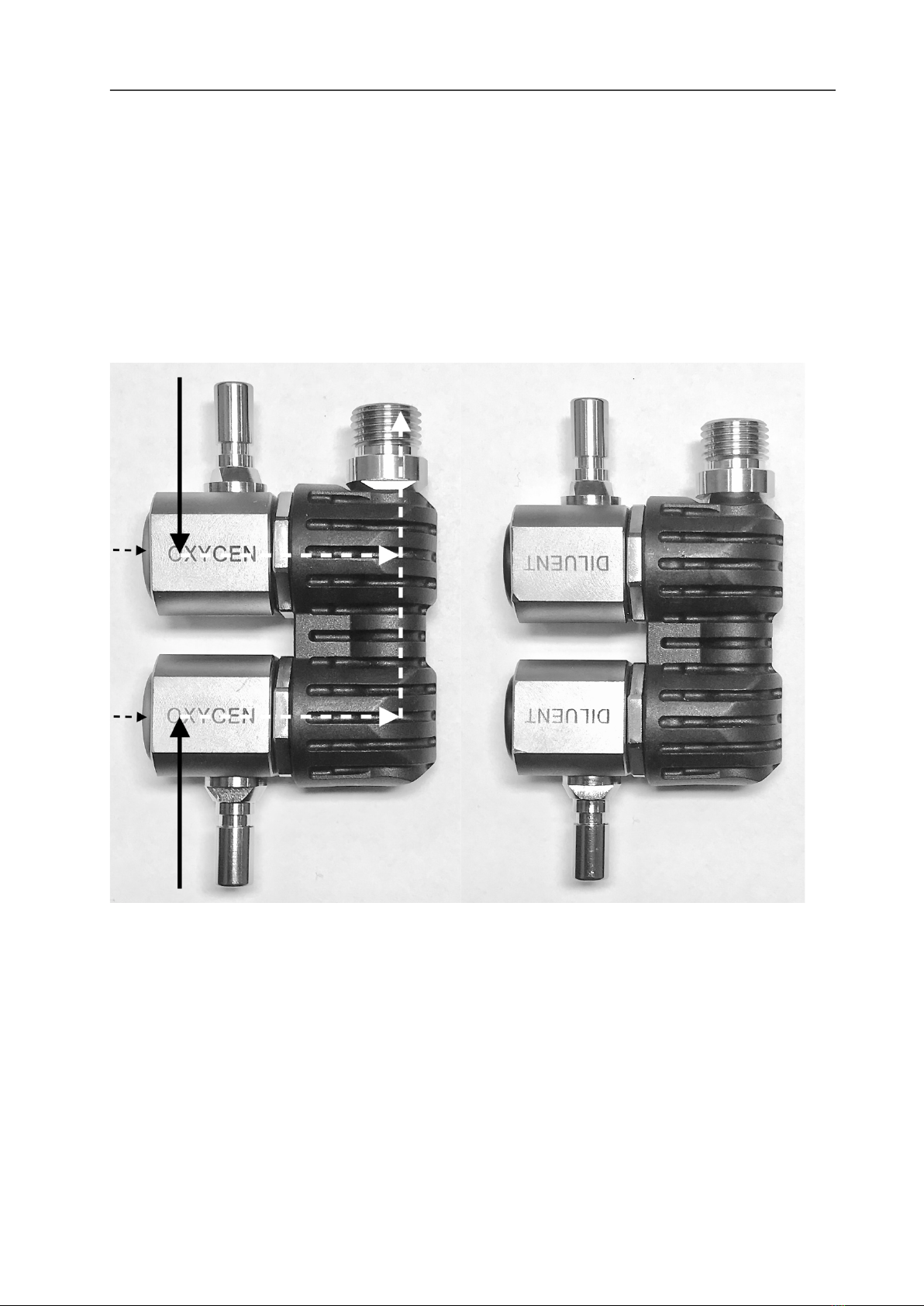
3.2 Gas flow paths ............................................................................................... 9!
3.3 Single Swivel Inflators - RBV07 & RBV07A .................................................... 9!
3.4 Dual Swivel Inflators - RBV07/DUAL & RBV07A/DUAL ............................... 10!
3.5 Single Swivel Inflators with Flowstop Shutoff - RBV07/SO & RBV07A/SO .. 11!
3.6 Dual Swivel Inflators with Shutoff - RBV07/DUAL/SO & RBV07A/DUAL/SO
........................................................................................................................... 12!
3.7 Recommended Position of the Collar of the GC3 Flowstop ......................... 13!
4. Service Kit Contents and Tools .......................................................... 14!
4.1 Service Kit Contents ..................................................................................... 14!
4.2 Tools Needed ............................................................................................... 15!
5. Disassembly Instructions .................................................................... 16!
5.1 General overview: main disassembly steps ................................................. 16!
5.2 Unscrew the 5/16” inflator stem(s) from the inflator body ............................. 16!
5.3 Unscrew the GC3 Flowstop isolator from the 5/16”-9/16” adapter ............... 17!
5.4 Unscrew the 5/16”-9/16” adapter(s) from the outlet body or inflator body .... 18!
5.5 Remove the inflator body from the outlet body ............................................. 19!
5.6 Unscrew the blue or green push button from the inflator spindle ................. 21!
5.7 Remove the O-ring from the inflator body .................................................... 23!
5.8 Remove low profile counterlung inlet elbow from counterlung ..................... 26!
5.9 Remove O-rings from MP counterlung inflator hose..................................... 27!
5.10 When GC3 Flowstop is fitted: remove O-rings from both ends of MP hose27!
AP50 Medium Pressure (MP) hose disassembly ............................................... 28!
5.11 Remove circlip from snap connector body ................................................. 28!
5.12 Remove sliding collar from snap connector body ....................................... 28!
5.13 Remove spring from snap connector body ................................................. 28!
5.14 Remove 4 ball bearings from snap connector body ................................... 29!
5.15 Unscrew Schraeder valve from snap connector body ................................ 29!
5.16 Remove O-ring from snap connector body ................................................. 30!
6. Clean and Replace Service Parts ....................................................... 31!
6.1 Ultrasonically clean deposits from all metal parts ......................................... 33!
6.2 Replace all O-rings with new ones from the Service Kit ............................... 34!
6.3 How to lightly grease O-rings ....................................................................... 34!
7. Assembly Instructions ......................................................................... 36!
7.1 General overview: main assembly steps ...................................................... 36!

AP Diving Ltd. RBV07 Swivel Inflator Range Maintenance Manual
Page 3 of 50
7.2 Place a new O-ring into the inflator body...................................................... 36!
7.3 Screw the blue or green push button onto the inflator spindle ...................... 37!
7.4 Fit a new O-ring onto the inflator body and locking ring ............................... 39!
7.5 Connect the inflator body to the outlet body ................................................. 40!
7.6 Screw the 5/16”-9/16” adapter(s) back into the outlet body or inflator body . 41!
7.7 Screw the GC3 Flowstop isolator back into the 5/16”-9/16” adapter ............ 43!
7.8 Screw the 5/16” inflator stem(s) back into the inflator body .......................... 43!
7.9 Fit new O-rings to MP counterlung inflator hose .......................................... 44!
7.10 Fit low profile counterlung inlet elbow back onto counterlung .................... 45!
7.11 When a GC3 Flowstop is fitted: fit new O-rings to both ends of MP hose .. 46!
7.12 Place the yellow locking strap back onto the GC3 isolator. ........................ 47!
AP50 hose assembly ......................................................................................... 47!
7.13 Fit new O-ring inside snap connector body ................................................ 47!
7.14 Screw new Schraeder valve into snap connector body .............................. 48!
7.15 Push 4 ball bearings back into snap connector body ................................. 48!
7.16 Put spring onto snap connector body ......................................................... 48!
7.17 Push sliding collar onto snap connector body ............................................ 49!
7.18 Refit circlip onto snap connector body........................................................ 49!
8. Testing Instructions ............................................................................. 50!
8.1 Test for leaks and proper operation.............................................................. 50!

AP Diving Ltd. RBV07 Swivel Inflator Range Maintenance Manual
Page 4 of 50
1. Introduction
1.1 Functional description
The AP RBV07 Swivel inflator range is a series of breathing gas inflators designed for use
with any AP Inspiration rebreather fitted with back-mounted counterlungs. Their unique
property is the swivel design with rotating inlet ports - which make it easy for the diver to plug
in various breathing gasses before and/or during the dive.
1.2 Servicing
Before servicing these swivel inflators, you must receive instruction and certification in the
maintenance of these inflators by AP Diving Ltd.
Without the correct training it is possible to service and configure the RBV07 Swivel inflators
incorrectly in an unsafe manner. Factory or Dealer prescribed service for these inflators is
recommended at least once annually.
The Inspiration, Evolution and Evolution+ closed circuit rebreathers’ CE certification to
EN14143 is unaffected by the fitting of this RBV07 Swivel inflators.
The RBV07 swivel inflators meet the requirements of the Personal Protective Equipment
Directive 89/686/EEC – CE certification when fitted to an AP Diving rebreather.
WARNING: When servicing the RBV07 swivel inflators it is VERY important that all parts
that may suffer wear and tear get replaced. It is also very important that the correct tools are
used to avoid damaging any part of the inflator in the disassembly and assembly process.
Please don’t try to save money by re-using parts that really should be replaced during a
proper servicing action.
B
The numbers between brackets after the part names in the disassembly and assembly
chapters correspond to the sequence numbers in the diagrams in chapter 2.
1.3 Warranty
The RBV07 Swivel inflators are covered by an AP 2 year warranty against defects in
materials or workmanship. This warranty is only offered to the original purchaser and is not
transferable. A copy of the receipt must be presented whenever obtaining warranty service.
1.4 Copyright and Applicable Law
This Maintenance Manual is copyrighted, all rights reserved. It may not, in whole or in part,
be copied, photocopied, reproduced, translated, or reduced to any electronic medium
(including the Internet) or machine-readable form without prior consent in writing from
AP Diving Ltd.
All products are sold on the strict understanding that only English Law applies in cases of
warranty claims and product liability, regardless of where the equipment is purchased or
used. Should a claim be made then the venue for this would be in Truro, England.
© 2019 AP Diving Ltd.
RBV07 Swivel Inflator Range Maintenance Manual

AP Diving Ltd. RBV07 Swivel Inflator Range Maintenance Manual
Page 5 of 50
3. RBV07 Swivel Inflator Range Exploded Diagrams and
Parts Lists
3.1 RBV07(A) Single Swivel Inflator main assembly
NUMBER
DESCRIPTION
PART NUMBER
QUANTITY
1
Push Button (Green or Blue)
AP_43
1
2
Spring
AP_43_A
1
3
Inflator Spindle
AP_52_C
1
4
BS-006-N70 O-ring
BS_006_N70
1
5
BS-010-N70 O-ring
BS_010_N70
3
6
BS-111-N70 O-ring
BS_111_N70
1
7
Single Outlet Body
RBV_07_01
1
8
Inflator Body
RBV_07_02
1
9
5/16” Inflator Stem
RBV_07_03
1
10
Locking Nut
RBV_07_04
1
11
5/16” – 9/16” Adapter
RBV_07_08
1
NOTE:
- RBV07 is the Diluent version, with blue push buttons and “DILUENT” engraving
- RBV07A is the Oxygen version, with green pushbuttons and “OXYGEN” engraving

AP Diving Ltd. RBV07 Swivel Inflator Range Maintenance Manual
Page 6 of 50
3.2 RBV07(A)/DUAL Dual Swivel Inflator main assembly
NUMBER
DESCRIPTION
PART NUMBER
QUANTITY
1
Push Button (Green or Blue)
AP_43
2
2
Spring
AP_43_A
2
3
Inflator Spindle
AP_52_C
2
4
BS-006-N70 O-ring
BS_006_N70
2
5
BS-010-N70 O-ring
BS_010_N70
5
6
BS-111-N70 O-ring
BS_111_N70
2
7
Inflator Body
RBV_07_02
2
8
5/16” Inflator Stem
RBV_07_03
2
9
8 Edge Locking Nut
RBV_07_04_8
2
10
5/16” – 9/16” Adapter
RBV_07_08
1
11
Dual Outlet Body
RBV_07_09
1
NOTE:
- RBV07/DUAL is the Diluent version, with blue push buttons and “DILUENT” engraving
- RBV07A/DUAL is the Oxygen version, with green pushbuttons and “OXYGEN”
engraving
!

AP Diving Ltd. RBV07 Swivel Inflator Range Maintenance Manual
Page 7 of 50
3.3 RBV07(A)/SO Single Swivel Inflator with Shutoff Valve main assembly
NUMBER
DESCRIPTION
PART NUMBER
QUANTITY
1
Push Button (Green or Blue)
AP_43
1
2
Spring
AP_43_A
1
3
BS-006-N70 O-ring
BS_006_N70
1
4
BS-010-N70 O-ring
BS_010_N70
4
5
BS-111-N70 O-ring
BS_111_N70
1
6
Single Outlet Body
RBV_07_01
1
7
5/16” Inflator Stem
RBV_07_03
1
8
Locking Nut
RBV_07_04
1
9
Shutoff Inflator Body
RBV_07_05
1
10
Shutoff Inflator Spindle
RBV_07_07
1
11
5/16” – 9/16” Adapter
RBV_07_08
2
NOTE:
- RBV07/SO is the Diluent version, with blue push buttons and “DILUENT” engraving
- RBV07A/SO is the Oxygen version, with green pushbuttons and “OXYGEN” engraving
!

AP Diving Ltd. RBV07 Swivel Inflator Range Maintenance Manual
Page 8 of 50
3.4 RBV07(A)/DUAL/SO Dual Swivel Inflator with Shutoff Valve
main assembly
NUMBER
DESCRIPTION
PART NUMBER
QUANTITY
1
Push Button (Green or Blue)
AP_43
2
2
Spring
AP_43_A
2
3
Inflator Spindle
AP_52_C
1
4
BS-006-N70 O-ring
BS_006_N70
2
5
BS-010-N70 O-ring
BS_010_N70
6
6
BS-111-N70 O-ring
BS_111_N70
2
7
Inflator Body
RBV_07_02
1
8
5/16” Inflator Stem
RBV_07_03
2
9
8 Edge Locking Nut
RBV_07_04_8
2
10
Shutoff Inflator Body
RBV_07_05
1
11
Shutoff Inflator Spindle
RBV_07_07
1
12
5/16” – 9/16” Adapter
RBV_07_08
2
13
Dual Outlet Body
RBV_07_09
1
NOTE:
- RBV07/DUAL/SO is the Diluent version, with blue push buttons and “DILUENT”
engraving
- RBV07A/DUAL/SO is the Oxygen version, with green pushbuttons and “OXYGEN”
engraving
!

AP Diving Ltd. RBV07 Swivel Inflator Range Maintenance Manual
Page 9 of 50
3. General Information
3.1 Four versions
There are four versions of the RBV07 Swivel inflator within the range. All four versions are
available in both a Diluent as well as an Oxygen model, making a total of eight different
models.
Note: The oxygen models have the letter "A" as a suffix in their part code.
3.2 Gas flow paths
In the pictures below (sections 3.3 to 3.6) the dotted arrows indicate the gas flow through the
inflator when the push button is operated. These are "on-demand" gas flow paths which are
normally blocked but can be temporarily opened by pushing the green or blue push button.
In the case of the four Swivel Inflator models with Flowstop shutoff (sections 3.5 & 3.6) the
solid arrows indicate a straight-through gas flow path through the inflator i.e. a continuous
gas flow regardless of whether the push button is operated. The gas flows uninterrupted from
the inlet through the inflator to the outlet to which the GC3 Flowstop is attached. The gas flow
can of course still be blocked by means of the slider on the GC3 Flowstop.
3.3 Single Swivel Inflators - RBV07 & RBV07A
The RBV07(A) has one MP (Medium Pressure) inlet and one MP outlet.
The RBV07(A) allows the diver to connect either an onboard or an offboard gas source. This
is made easy by virtue of the swivel design in which the inlet port section of the inflator can
rotate through 360 degrees.
The gas flow path is "on demand", i.e. gas only flows through when the button is pushed.
!

AP Diving Ltd. RBV07 Swivel Inflator Range Maintenance Manual
Page 10 of 50
3.4 Dual Swivel Inflators - RBV07/DUAL & RBV07A/DUAL
The RBV07(A)/DUAL has two MP inlets and one MP outlet. Both inlets rotate to facilitate
connection to wherever the gas sources are located.
The extra inlet (on the bottom in the picture below) allows the simultaneous connection of
another gas source, either onboard or offboard. Each gas source can be operated by its own
separate push button.
The gas flow paths are both "on demand", i.e. gas only flows when one of the buttons is
pushed.
!

AP Diving Ltd. RBV07 Swivel Inflator Range Maintenance Manual
Page 11 of 50
3.5 Single Swivel Inflators with Flowstop Shutoff - RBV07/SO &
RBV07A/SO
The RBV07(A)/SO has one MP inlet and two MP outlets.
The central outlet is “straight-through”, which means the gas always flows from the inlet to
this outlet regardless of the push button operation. This outlet is fitted with a GC3 Flowstop
in-line gas isolator, which offers the option of shutting off the gas flow.
This outlet is typically connected to the solenoid (on the Oxygen model) or ADV (on the
Diluent model). It gives the diver the option of blocking the gas flow to the solenoid or ADV in
the unlikely event of a “solenoid stuck-open” or "ADV free-flow" fault situation or for any other
reason the diver may want to isolate these gasses - for example, when performing a “diluent
flush” cell check.
!

AP Diving Ltd. RBV07 Swivel Inflator Range Maintenance Manual
Page 12 of 50
3.6 Dual Swivel Inflators with Shutoff - RBV07/DUAL/SO &
RBV07A/DUAL/SO
The RBV07(A)/DUAL/SO has two MP inlets and two MP outlets.
The central outlet is “straight-through”, which means the gas always flows from the inlet to
this outlet regardless of the push button operation. This outlet is fitted with a GC3 Flowstop
in-line gas isolator, which offers the option of shutting off the gas flow.
This outlet is typically connected to the solenoid (on the Oxygen model) or ADV (on the
Diluent model). It gives the diver the option of blocking the gas flow to the solenoid or ADV in
the unlikely event of a “solenoid stuck-open” or "ADV free-flow" fault situation or for any other
reason the diver may want to isolate these gasses - for example, when performing a “diluent
flush” cell check.
The extra inlet (on the bottom in the picture below) allows for the simultaneous connection of
another gas source. The swivel design facilitates connection to wherever the gas source is
located, onboard or off. It is operated by its own separate push button.
NOTE: The service procedure for the GC3 Flowstop in-line gas isolator as fitted to the
RBV07(A)/SO and RBV07(A)/DUAL/SO is not described in this service manual.
There is a separate manual available that fully describes the service procedure for this item.

AP Diving Ltd. RBV07 Swivel Inflator Range Maintenance Manual
Page 13 of 50
3.7 Recommended Position of the Collar of the GC3 Flowstop
The GC3 Flowstop gas isolator features a knurled slider which functions to open or close off
the gas flow. The orientation of this slider determines which slider direction is open and
which is closed.
Although the orientation of the slider is reversible (by dis-assembly/re-assembly), APD
strongly recommends that you stick to the position as it is delivered from the factory when
fitted to the RBV07(A)/SO or RBV07(A)/DUAL/SO inflator.
From a safety and natural handling point-of-view this is the best position, for two reasons:
1) It makes closing the valve a positive pull-up action;
2) If the yellow locking strap gets accidentally dislodged, the valve “fails-open” in the
open position rather than in the closed position. See also paragraph 7.8.
The recommended position of the collar is with the laser-engraved text “OPEN” text closest
to the main body of the inflator, as show in the pictures below:

AP Diving Ltd. RBV07 Swivel Inflator Range Maintenance Manual
Page 14 of 50
4. Service Kit Contents and Tools
4.1 Service Kit Contents
WARNING: When replacing O-rings, next to the size, the hardness of the O-rings
(declared in degrees Shore, and indicated by the suffixes N70 and N90 in the parts lists in
chapter 2) is ESSENTIAL for proper operation.
If, against our recommendation, you choose to select your O-rings to come from another
source than AP Diving Ltd., make sure you select the right type in size AND hardness AND
material (composition).
When servicing the RBV07 Swivel inflator, you can make use of a total of 10 AP Diving
service kits:
- 4 for each diluent version of the inflator,
- 4 for each oxygen version of the inflator,
- 1 for the AP50 MP hose, and
- 1 for the GC3 Flowstop in-line gas isolator.
-
Note that there is a separate AP Diving maintenance manual for the GC3 Flowstop that also
describes its service kit contents.
The contents of the various service kits are described in detail in chapter 6.
The order names for the service kits are as follows:
RBV07KIT
Single Diluent Swivel Inflator + outlet Hose + Counterlung Inlet Service Kit
RBV07AKIT
Single Oxygen Swivel Inflator + outlet Hose + Counterlung Inlet Service Kit
RBV07/DUAL/KIT
Dual Diluent Swivel Inflator + outlet Hose + Counterlung Inlet Service Kit
RBV07A/DUAL/KIT
Dual Oxygen Swivel Inflator + outlet Hose + Counterlung Inlet Service Kit
RBV07/SO/KIT
Single Diluent Swivel Inflator with Shutoff + outlet Hose + Counterlung Inlet +
Flowstop outlet-Hose Service Kit
RBV07A/SO/KIT
Single Oxygen Swivel Inflator with Shutoff + outlet Hose + Counterlung Inlet +
Flowstop outlet-Hose Service Kit
RBV07/DUAL/SO/KIT
Dual Diluent Swivel Inflator with Shutoff + outlet Hose + Counterlung Inlet +
Flowstop outlet-Hose Service Kit
RBV07A/DUAL/SO/KIT
Dual Oxygen Swivel Inflator with Shutoff + outlet Hose + Counterlung Inlet +
Flowstop outlet-Hose Service Kit
AP50KIT
AP50 snap connector Hose Service Kit
FLOWSTOP SERVICE
KIT – GC3A
GC3 Flowstop In-line Gas Isolator Service Kit
!

AP Diving Ltd. RBV07 Swivel Inflator Range Maintenance Manual
Page 15 of 50
4.2 Tools Needed
There are no special tools needed for servicing the RBV07 Swivel inflator.
Normal tools needed are:
- A 5mm Allen key
- 8, 12,13, 14 and 24mm spanners
- A torque wrench for low torque settings (down to 4 Newton Meter)
- A screw driver
- a bench vice, fitted with soft jaws
- O-ring picking tools
- Oxygen-compatible grease
o see chapter 5 for remarks about when you need to keep this device in oxygen
service
- (Access to) an ultrasonic bath for cleaning the metal parts.
WARNING: Do NOT use aggressive chemicals. They might damage the metal plating of
the RBV07 Swivel inflator. Use an ultrasonic cleaning bath with a suitable cleaning fluid. A
very good cleaning fluid is Biox “O2” immersion fluid. See WWW.BIOXINT.COM for further
information and distributors.
The use of rubber gloves while re-assembling the RBV07 Swivel inflator is recommended to
avoid rendering the RBV07 Swivel inflator oxygen unclean due to human touch.

AP Diving Ltd. RBV07 Swivel Inflator Range Maintenance Manual
Page 16 of 50
5. Disassembly Instructions
5.1 General overview: main disassembly steps
Despite the fact that all eight models of the RBV07 range of inflators have different layouts
and functionality, the service procedures for these inflators have a lot in common. For that
reason, the disassembly steps of the 8 different models are not described separately for
each one, but are consolidated into steps that are common to all.
There are four main steps in the disassembly process:
1. Unscrew and remove all inlet and outlet adapters:
a. The 5/16” inflator stems,
b. The 5/16”-9/16” adapters and
c. The GC3 Flowstop isolators (where fitted).
2. Remove the swivelling inflator bodies (the parts with the blue or green buttons) from
the outlet bodies by unscrewing the connecting locking nuts from the outlet bodies.
3. Remove the blue or green push buttons by unscrewing them from the inflator
spindles, and subsequently pull out the inflator spindles.
4. Remove all O-rings and clean the metal parts.
5.2 Unscrew the 5/16” inflator stem(s) from the inflator body
- Use an 8 mm spanner to unscrew the inflator stem from the inflator body.
- Remove the O-ring and discard it.

AP Diving Ltd. RBV07 Swivel Inflator Range Maintenance Manual
Page 17 of 50
5.3 Unscrew the GC3 Flowstop isolator from the 5/16”-9/16” adapter
- ATTENTION: This step only applies to the RBV07(A)/SO and RBV07(A)/DUAL/SO
versions of the inflator, which are fitted with a GC3 in-line gas isolator.
- Remove the yellow locking strap from the GC3 isolator.
- Use a 14 mm spanner to unscrew the GC3 Flowstop from its adapter.
- NOTE: the service procedure for the GC3 Flowstop gas isolator is described in a
separate AP maintenance manual, available on the AP Diving website.
- If the adapter becomes unscrewed from the inflator body in the process: don’t worry, as
the adapter also needs to be unscrewed anyway. If this happens, use a 12 mm spanner
and a 14 mm spanner to separate the GC3 and the adapter from each other.

AP Diving Ltd. RBV07 Swivel Inflator Range Maintenance Manual
Page 18 of 50
5.4 Unscrew the 5/16”-9/16” adapter(s) from the outlet body or inflator
body
- Use a 5 mm Allen key to unscrew the adapter from the single or dual outlet body or
inflator body, counter-clockwise.
- Remove the O-ring from the adapter and discard it.

AP Diving Ltd. RBV07 Swivel Inflator Range Maintenance Manual
Page 19 of 50
5.5 Remove the inflator body from the outlet body
- Use a permanent marker to place a small mark on both the locking ring and the outlet
body. This serves to later on, during assembly, act as an indicator as to how far to screw
the locking nut back into the outlet body.
- Clamp the outlet body into a bench vice.
ATTENTION: when using the vice, make sure to fit it with soft jaws (plastic or fibre).
This avoids damaging the clamped inflator body and its nickel-plated coating.
- ATTENTION: when clamping the black synthetic dual outlet body into the vice, use as
little force as possible to avoid distorting the dual outlet body.
- Use a 24 mm spanner to unscrew the locking nut and inflator body counter-clockwise
from the outlet body.
- ATTENTION: Make sure the jaw of the spanner ONLY touches the inflator body and the
locking ring, i.e. the parts with “OXYGEN” or “DILUENT” laser engraving and containing
the blue or green push button. The jaw of the spanner should NOT touch the outlet body.

AP Diving Ltd. RBV07 Swivel Inflator Range Maintenance Manual
Page 20 of 50
- Avoid the use of an adjustable spanner, as it might damage the coating of the inflator
body and locking ring.
- Remove the large O-ring from the stem of the inflator body, discard it and subsequently
lift the locking nut from the inflator body.
This manual suits for next models
6
Table of contents
Other AP Diving Power Tools manuals
Popular Power Tools manuals by other brands

jcb
jcb JCB-18JS Instructions & user's manual

PREMIUM BALLON ACCESSORIES
PREMIUM BALLON ACCESSORIES Cool Aire 4 manual

Spellbinders
Spellbinders Artisan X-plorer instructions

MasterCraft
MasterCraft 54-4790-6 owner's manual

LEMKEN
LEMKEN VarioPack 80 WDP 70 operating instructions

Fromm
Fromm A482 Operation manual & spare parts list