Fromm A482 Guide

OPERATION MANUAL / SPARE PARTS LIST
PNEUMATIC COMBINATION
PUSHER TYPE TOOL
MODEL A482
13.4620.01
13462001.en-3/MAS/© 04.12
Original instructions

2
INDEX PAGE
1 SAFETY INSTRUCTIONS 3
2 WARRANTY CONDITIONS AND LIABILITY 4
3 APPROPRIATE USE 4
4 TECHNICAL DATA 4
4.1 Tool size (without suspension bracket) . . . . . . . . . . . . . . . . . . . . . . . . . . . . . . . 4
4.2 Steel strap . . . . . . . . . . . . . . . . . . . . . . . . . . . . . . . . . . . . . . . . . . . . . . . . . . . . . 4
4.3 Seals . . . . . . . . . . . . . . . . . . . . . . . . . . . . . . . . . . . . . . . . . . . . . . . . . . . . . . . . . 5
4.4 Joint. . . . . . . . . . . . . . . . . . . . . . . . . . . . . . . . . . . . . . . . . . . . . . . . . . . . . . . . . . 5
4.5 Sound information . . . . . . . . . . . . . . . . . . . . . . . . . . . . . . . . . . . . . . . . . . . . . . . 5
4.6 Vibration information . . . . . . . . . . . . . . . . . . . . . . . . . . . . . . . . . . . . . . . . . . . . . 5
5 INSTALLATION 5
5.1 Compressed air connection. . . . . . . . . . . . . . . . . . . . . . . . . . . . . . . . . . . . . . . . 5
5.2 Suspension of tool. . . . . . . . . . . . . . . . . . . . . . . . . . . . . . . . . . . . . . . . . . . . . . . 6
6 OPERATION 6
6.1 Feeding the strapping . . . . . . . . . . . . . . . . . . . . . . . . . . . . . . . . . . . . . . . . . . . . 6
6.2 Introducing the tool . . . . . . . . . . . . . . . . . . . . . . . . . . . . . . . . . . . . . . . . . . . . . . 6
6.3 Tensioning the strapping . . . . . . . . . . . . . . . . . . . . . . . . . . . . . . . . . . . . . . . . . 7
6.4 Sealing the strapping . . . . . . . . . . . . . . . . . . . . . . . . . . . . . . . . . . . . . . . . . . . . 7
6.5 Releasing the tool . . . . . . . . . . . . . . . . . . . . . . . . . . . . . . . . . . . . . . . . . . . . . . . 7
6.6 Tension regulation . . . . . . . . . . . . . . . . . . . . . . . . . . . . . . . . . . . . . . . . . . . . . . 7
7 SPARE PARTS LIST 13.4620.01 10
8 JOINT CONTROL 13
9 MAINTENANCE 13
9.1 Air-unit . . . . . . . . . . . . . . . . . . . . . . . . . . . . . . . . . . . . . . . . . . . . . . . . . . . . . . . 13
9.2 Cleaning . . . . . . . . . . . . . . . . . . . . . . . . . . . . . . . . . . . . . . . . . . . . . . . . . . . . . 13
9.3 Lubrication. . . . . . . . . . . . . . . . . . . . . . . . . . . . . . . . . . . . . . . . . . . . . . . . . . . . 13
10 EXCHANGE OF WEARING PARTS 14
10.1 Exchange of tensioning wheel and slide plate. . . . . . . . . . . . . . . . . . . . . . . . . 14
10.2 Exchange of cutter, cutter jack, cutting jaws and notching knives. . . . . . . . . . 14
11 CHART OF TYPES 14

3
1 SAFETY INSTRUCTIONS
Read these instructions carefully. Failure to follow these instructions can result in severe personal injury.
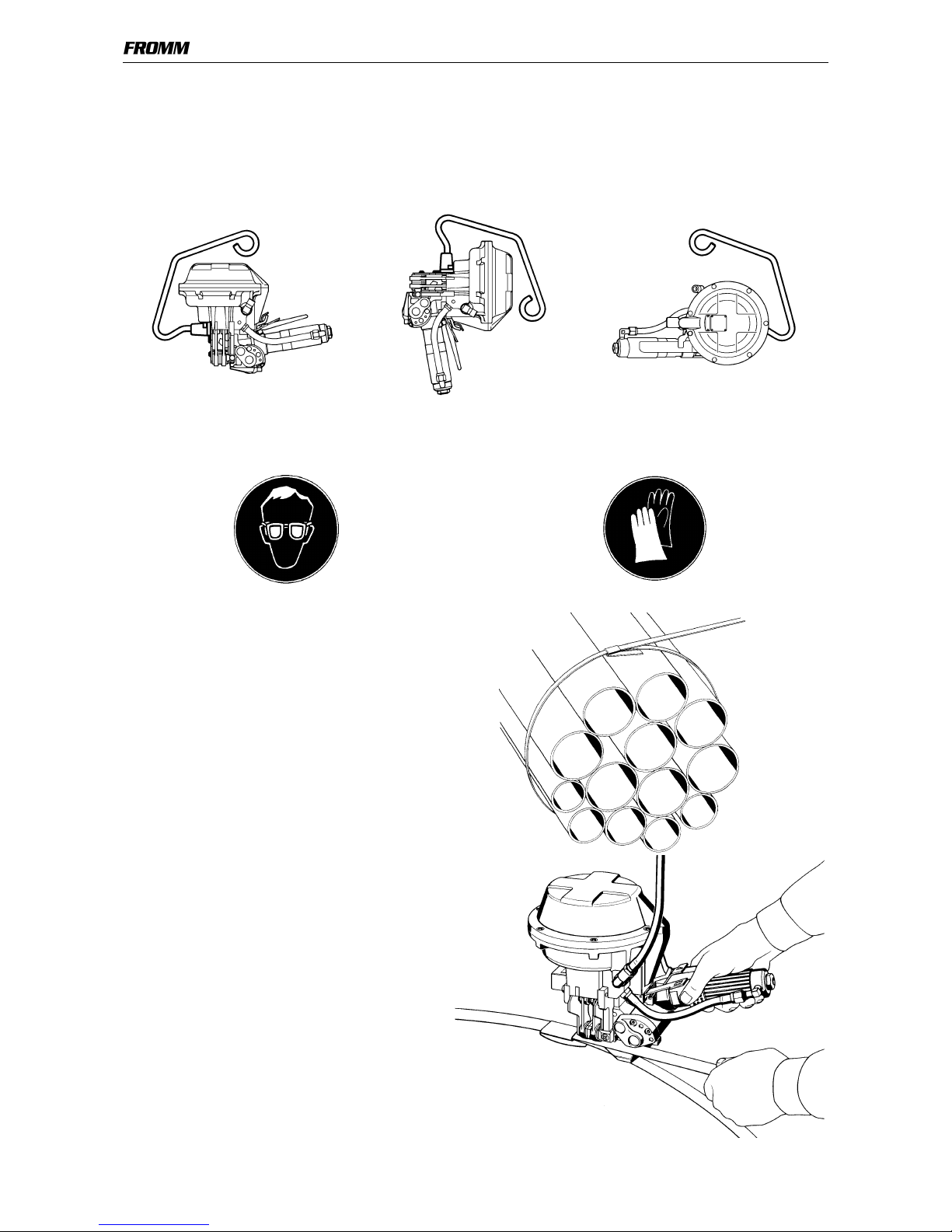
Eye injury hazard
Failure to wear safety glasses with side shields can result in
severe eye injury or blindness. Always wear safety glasses with
side shields which conform to ANSI Standard Z87.1.
Operation
Tool must not be used by persons not properly trained in their use.
Before tensioning strap, read and understand the tool operating
instructions. Failure to follow the operating instructions or improper
load positioning could result in strap breakage.
Become familiar with your tool and keep fingers away from areas
that can pinch or cut.
Joints
You are fully responsible to review the joints made by your tool.
Become familiar with the seal control and seal adjustment
described in this operation manual. Misformed joints may not
secure the load and could cause serious injury. Never handle or
ship any load with improperly formed joints.
Dispensing strap
Only dispense strap from a dispenser specifically designed for
strap.
Tuck strap end back into dispenser when not in use.
Protective gloves
When handling strap, always wear protective gloves.
Strap warnings
Never use strap as a means of pulling or lifting loads. Failure to
follow these warnings can result in severe personal injury.
Strap breakage hazard
Improper operation of the tool, excessive tensioning, using strap
not recommended for this tool or sharp corners on the load can
result in a sudden loss of strap tension or in strap breakage during
tensioning, which could result in the following:
• A sudden loss of balance causing you to fall.
• Both tool and strap flying violently towards your face.
Note as follows:
• If the load corners are sharp, use edge protectors.
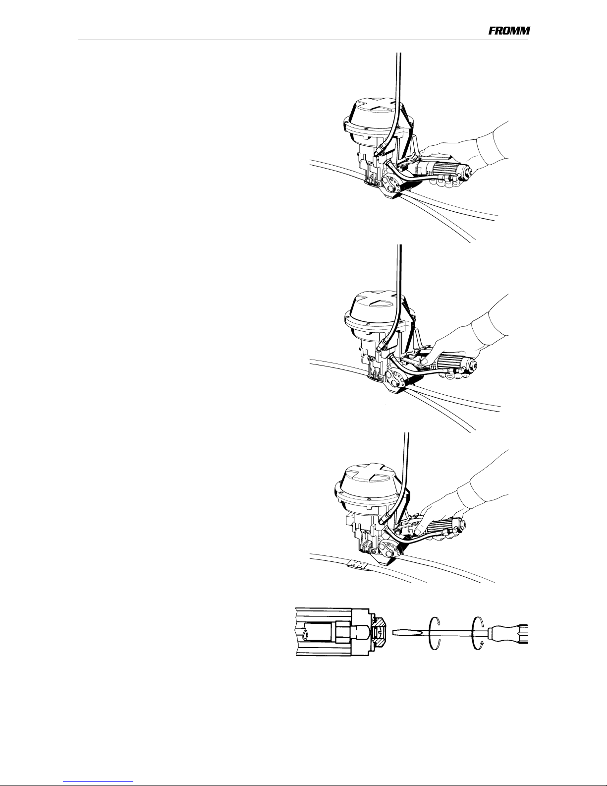
• Place the strap correctly around a properly positioned
load.
• Positioning yourself in-line with the strap, during
tensioning and sealing, can result in severe personal
injury from flying strap or tool. When tensioning or sealing,
position yourself to one side of the strap and keep all
bystanders away.
• Use the correct strap quality, strap width, strap gauge and
strap tensile strength recommended in this manual for
your tool. Using strap not recommended for this tool can
result in strap breakage during tensioning.
Cutting tensioned strap
When cutting strapping, use the proper strapping cutter and keep
other personnel and yourself at a safe distance from the strap.
Always stand to side of the strap, away from the direction the
loosened strap end will fly. Use only cutters designed for strap and
never hammers, pliers, hacksaws, axes, etc.
Fall hazard
Keep your working area tidy. Untidiness of your working area may
cause a risk of injury. Maintaining improper footing and/or balance
when operating the tool can cause you to fall. Before tensioning
and especially in elevated areas, always establish good balance.
Both feet should be securely placed on a flat, solid surface,
especially when working in elevated areas. Do not use the tool
when you are in an awkward position.
Pay attention to the rules and regulations for preventions of
accident which are valid for the work place.
Tool hazards
A well maintained tool is a safe tool!
Check tool regularly for broken or worn parts. Do not operate a
tool with broken or worn parts.
Never modify any tool. Modification can result in severe bodily
injury.

4
2 WARRANTY CONDITIONS AND LIABILITY
FROMM Holding AG warrants all its strapping tools and machine heads during a period of 90 days from the
date sale.
The warranty includes all deficiencies clearly resulting from poor manufacturing or faulty materials. Damage
claims as a result of production shutdowns and claims for damage to persons and to property resulting from
warranty deficiencies cannot be asserted by the customer.
The warranty excludes:
• wearing parts
• deficiencies resulting from improper installing, incorrect handling and maintaining the tool
• deficiencies resulting from using the tool without or with defective security- and safety devices
• disregard of directions in the operation manual
• arbitrary modifications of the tool
• deficient control of wearing parts
• deficient repair works of the tool
• Use of consumable products not recommended by FROMM Holding AG
We reserve the right to modify the product at any time in order to improve its quality.
3 APPROPRIATE USE
The tool model A482 has been designed to strap packages with steel strapping exclusively.
The warranty / liability excludes:
•non appropriate use of the tool,
•disregard of directions in the operation manual,
•disregard of control- and maintenance instructions.
4 TECHNICAL DATA
4.1 Tool size (without suspension bracket)
Tool: Package:
Length: 350 mm / 13.7" 460 mm / 18.1"
Width: 180 mm / 7.0" 420 mm / 16.5"
Height: 240 mm / 9.4" 220 mm / 8.7"
Weight
Without suspension bracket: 6.5 Kg / 14.3 lbs
With suspension bracket: 7.0 Kg / 15.4 lbs
Package: 1.3 Kg / 2.9 lbs
4.2 Steel strap
Width: 19 mm / 3/4" (see chart of types)
Thickness: 0.63 - 0.90 mm / .025 -.035" (see chart of types)
Quality: The A482 model allows the use of all current steel straps with tensile strengths
ranging from 600 - 1100 N/mm2/ 87 000 - 160 000 psi (see chart of types).
Straps with a low breaking elongation are unsuitable.

5
4.3 Seals
19 X 0.9 X 45 mm / 3/4" X.035 X 1 3/4", push-type with overlapping flanges
4.4 Joint
Joint strength: approx. 75% of the tensile strength of the steel strap
A double-notch (two pairs of cut notches) is made per cycle.
4.5 Sound information
The A-weighted equivalent continuous sound level at the work place of the machine operator is
typical 83 dB (A).
This value was determined according to DIN 45 635 T3 (11.85).
4.6 Vibration information
The weighted effective value of the acceleration typically amounts to less than 2,5m/s2.
This value was determined according to DIN EN 28 662 T1 (01.93).
5INSTALLATION
5.1 Compressed air connection
The compressed air should be connected to the tool preferably by a quick disconnector.
It is very important to clean the compressed air with an air unit consisting of a separator for water and dirt, a
pressure regulator with a manometer and a lubricator (see sketch).
Compressed air
Joining thread: G1/4
Working pressure: 5 bar / 72.5 psi
Max. air pressure: 6 bar / 87 psi.
Air flow of air unit: min. 780 Nl/min / 27.55 cu.ft /min with a maximum pressure drop of 0.5 bar / 7.25 psi.
Air consumption
Tensioning: approx. 3.5 Nl / 0.12 cu.ft uncompressed air per second with the air motor running.
Sealing: approx. 7.7 Nl / 0.27 cu.ft. uncompressed air per cycle.
app. 2%fall
Shut off valve
Drain of main air line
Main air line min. 2"
Air line min. 1/2"
Pressure adjustment valve
with manometer
Filter with
Lubricator
(1 - 2 drops/min.)
water separator
with shut off valve Air hose
max. length 5m (16ft.)
min. Ø-inside 9mm (3/8")
Coupling min. G1/4
Air unit min. G3/8

6
5.2 Suspension of tool
It is possible to suspend the tool on a spring loaded balancer using the suspension bracket A48.2303.
By swivelling the bracket the tool can be suspended in its three main working positions.
The suspension bracket is attached to the cover plate A48.2135 using the screws N1.1106 and the spring lock
washers N1.6220 supplied with the tool.
6OPERATION
6.1 Feeding the strapping
The strap is fed through the seal, around the
package to be strapped and again through the
seal.
The strap end is then bent.
The operator then tensions the loose hoop
manually making sure that the bent strap end is
adjacent to the object to be strapped.
6.2 Introducing the tool
The upper strap is held with the left hand;
the right hand lifts the air motor and introduces the
tool from the right to the left and from the rear to
the front.
The air motor is then released.
When handling strap, always wear
protective gloves and safety glasses
with side shields which conform to
ANSI Standard Z87.1.

7
6.3 Tensioning the strapping
The tension valve lever is pressed down.
The lever is caught completely and the strap is
tensioned until the air motor stalls.
If the cycle has to be interrupted the catch bolt has
to be pressed to the left.
6.4 Sealing the strapping
The sealing valve lever is pressed down until the
seal is cut and the upper strap sheared;
the tensioning process is interrupted
automatically.
6.5 Releasing the tool
The tool can be released from the strapping
without any further action after completing the
strapping cycle.
By lifting the air motor the strap end is removed
from the tool.
6.6 Tension regulation
The tension is regulated by the continuous
adjustment of the throttle screw.
The air supply is reduced by turning the screw
clockwise.
The throttle screw is located at the rear end of the
air motor.

2 31A
B
C
D
E
A48.2111
A48.2112
A48.2112
A48.2132
N7.1205
N1.6207
N1.6207 N2.2172
N2.2172
N1.1114
N1.1114
A48.2104
A48.2103
N1.2140
A48.2103
A48.2103
A48.2102
A48.2102
N1.5130
N2.5604
A38.3407
A38.3405
A48.2304 A48.2306
A48.2303
N1.1128
N1.6206
N1.6206
A48.2135
N1.5302
A48.2114
A48.2115
N1.1106
N1.1106
N1.6220
N1.6220
A48.2105
A48.2106
A48.2106
A48.2113
A48.2110
A38.1209
A48.2136
N6.6235
N6.6204
A38.1208
N2.5161
N3.1706
N6.6204
N2.5159
N1.2212
N1.2215
A48.2129
A38.1202
N2.5102
N3.1708
N6.6217
N6.6217
N6.6230
A38.1203
N2.5216
N2.5151
A48.2128
A48.1234
13462001.z
A48.1237
N6.5133
N6.5624
A48.2134
A48.2133
A48.2130
N6.6235
N2.5195
N1.1815
A48.2125
A48.0102
A48.0103

4 5 6 7
N2.5196
A48.2121
L2.1108
A48.1133
A48.1133
A48.1213
A48.2201
N1.2109
N1.1813
A48.2204
N2.2115
A48.2120
A48.2212
N1.1521
N1.5131
A48.2217
N6.5195
A48.2205
N3.2313
N3.4311
N3.4108
A48.2207
N2.3205
A48.2210
N1.1816
A48.2208
N3.2342
N6.6253
A48.2215
N3.1131 A48.1226
N3.3144
A48.2211
N3.2608
N3.2343
N1.1814
A48.2118
A48.2117
N1.2141
A48.2131
A48.2132
N1.2108
A48.2119
A48.2126
A48.2127
A48.2213
N1.1813
A48.0104
N3.2405
A48.2137
A48.2137
Loctite 222
Talcum
Mobilux EP2
Molykote BR 2 plus
41 Nm
Loctite 603
Loctite 542
Loctite 243
2,5 Nm
N1.1814

[ ] = Group * = Wearing parts
10 13462001.een
7 SPARE PARTS LIST 13.4620.01
13.4620.01 A482/19/0.80/ULT/7.0 A482.0001.01 22.12.10
Item-No. in group Pcs. Description Dimension Field
A38.1202 A48.0103 1 SECURITY VALVE SHELL B3
A38.1203 A48.0103 1 VALVE BOLT B3
A38.1208 A48.0103 1 SEALER VALVE SHELL B2
A38.1209 A48.0103 1 VALVE BOLT C2
A38.3405 A48.2303 2 RATCHET DISK E1
A38.3407 A48.2303 1 THRUST WASHER E1
[A48.0102] 1 JAW ASSEMBLY D3
[A48.0103] 1 CYLINDER BOTTOM A2
[A48.0104] 1 TENSIONING UNIT B7
A48.1133 2 TONG GUIDE D4+
A48.1213 *A48.0104 1 SLIDE PLATE D5
A48.1226 A48.0104 1 BEARING JACKET D7
A48.1234 A48.0103 1 CATCH B4
A48.1237 A48.0103 1 SIEVE B2
A48.2102 *A48.0102 4 CUTTING JAW D2+
A48.2103 *A48.0102 4 NOTCHING KNIFE D2+
A48.2104 A48.0102 2 JAW PIN D4
A48.2105 A48.0102 4 FRONT TOGGLE LINK C2
A48.2106 A48.0102 4 LEVER BOLT C2+
A48.2110 A48.0102 1 ROD BAR BOLT C3
A48.2111 A48.0102 1 SIDE PLATE C3
A48.2112 A48.0102 2 DISTANCE SUPPORT C2+
A48.2113 A48.0102 2 SPACER BUSH C3
A48.2114 A48.0102 1 SIDE PLATE C1
[A48.2115] A48.0103 1 CYLINDER BOTTOM A2
A48.2117 1 PISTON PLATE B5
A48.2118 1 CYLINDER COVER A5
A48.2119 *1 CUTTER C4
A48.2120 *A48.0104 1 CUTTER JACK D4
[A48.2121] A48.0104 1 CONNECTION PLATE C5
A48.2125 A48.0103 1 LEVER BODY B4
A48.2126 A48.0103 1 SEALING VALVE LEVER C4
A48.2127 A48.0103 1 TENSIONER VALVE LEVER B4
A48.2128 A48.0103 1 LEVER SHAFT B4
A48.2129 A48.0103 1 CATCH PIN C4
A48.2130 1 HANDLE A3
A48.2131 1 DIAPHRAGM A5
A48.2132 A48.0102 4 SCREW B2+
A48.2133 1 JAW GUIDE A3
A48.2134 1 JAW GUIDE B2
A48.2135 1 COVER PLATE C1
A48.2136 A48.0102 1 PISTON ROD B2
A48.2137 A48.2121 2 BOLT D5
[A48.2201] *A48.0104 1 TENSIONING BODY D5
A48.2204 A48.0104 2 CENTERING BUSH C5
[A48.2205] A48.0104 1 GEAR BODY C6
A48.2207 A48.0104 1 TENSION SHAFT C6
A48.2208 A48.0104 1 WORM WHEEL C7
A48.2210 A48.0104 1 END COVER C7
A48.2211 *A48.0104 1 TENSIONING WHEEL E5
A48.2212 A48.0104 1 PIVOT PIN D4

[ ] = Group * = Wearing parts
11
13462001.een
A48.2213 A48.0104 1 END COVER E4
A48.2215 A48.0104 1 WORM C7
[A48.2217] A48.0103 1 HOSE D6
[A48.2303] 1 SUSPENSION BRACKET D1
[A48.2304] A48.2303 1 SUSPENSION BRACKET E1
A48.2306 A48.2303 1 FLANGE SHAFT E2
[L2.1103] L2.1108 1 PLANET SHAFT --
[L2.1108] 1 AIR MOTOR D7
L2.1201 L2.1108 1 EXHAUST RING --
L2.1203 L2.1212 1 PLASTIC JACKET --
[L2.1212] L2.1108 1 HOUSING --
[L2.1223] L2.1108 1 PLANET SHAFT --
L2.1301 L2.1323 1 END PLATE --
L2.1302 L2.1323 1 PARALLEL PIN --
L2.1303 L2.1323 1 CYLINDER --
L2.1304 *L2.1323 5 VANE --
L2.1305 L2.1323 1 ROTOR --
L2.1308 L2.1108 1 DAMPER --
L2.1309 L2.1103 1 PLANET SHAFT --
L2.1310 L2.1103 2 NEEDLE CAGE --
L2.1311 L2.1103 2 SPUR WHEEL --
L2.1312 L2.1103 2 SHAFT --
L2.1313 L2.1108 1 BEARING RING --
L2.1314 L2.1323 1 END PLATE --
[L2.1323] L2.1108 1 MOTOR CELL --
L2.1402 L2.1223 32 BEARING NEEDLE --
L2.1403 L2.1223 2 SPUR WHEEL --
L2.1404 L2.1223 2 SHAFT --
L2.1405 L2.1108 1 BEARING RING --
L2.1408 L2.1223 1 PLANETARY CAGE --
L2.1409 L2.1413 1 AIR INLET RING --
L2.1410 L2.1413 1 TENSION SCREW --
L2.1411 L2.1413 1 THROTTLE HEAD --
L2.1412 L2.1413 1 THROTTLE SCREW --
[L2.1413] L2.1108 1 AIR INLET HEAD --
L2.1505 L2.1323 1 KEY --
N1.1106 A48.2303 2 SCREW M6 X 20 E2
N1.1114 A48.0104 2 SCREW M5 X 25 E3
N1.1128 2 SCREW M8 X 60 B1
N1.1521 A48.0104 1 HEXAGON SCREW M5 X 16 D5
N1.1813 2 RAISED CTRS. HEAD SCREW M5 X 16 A4+
N1.1814 7 RAISED CTRS. HEAD SCREW M5 X 25 A4+
N1.1815 2 RAISED CTRS. HEAD SCREW M6 X 25 B4
N1.1816 A48.0104 2 RAISED CTRS. HEAD SCREW M4 X 16 C7
N1.2108 A48.0104 2 COUNTERSUNK SCREW M6 X 16 C4
N1.2109 A48.0104 1 COUNTERSUNK SCREW M5 X 10 D5
N1.2140 A48.0102 1 COUNTERSUNK SCREW M5 X 45 D4
N1.2141 1 COUNTERSUNK SCREW M8 X 30 B5
N1.2212 A48.0103 1 COUNTERSUNK SCREW M4 X 25 C3
N1.2215 A48.0103 1 COUNTERSUNK SCREW M4 X 30 C3
N1.5130 A48.2303 2 HEXAGON NUT M10 D1
N1.5131 A48.0104 1 HEXAGON NUT M5 D5
N1.5302 A48.0102 1 RETAINING NUT M5 C1
13.4620.01 A482/19/0.80/ULT/7.0 A482.0001.01 22.12.10
Item-No. in group Pcs. Description Dimension Field

[ ] = Group * = Wearing parts
12 13462001.een
N1.6206 2 SPRING LOCK WASHER M8 B1+
N1.6207 A48.0104 2 SPRING LOCK WASHER M5 E3+
N1.6220 A48.2303 2 SPRING LOCK WASHER M6 E2
N2.1202 L2.1108 1 SECURITY RING J32 --
N2.2115 A48.0104 1 PARALLEL PIN 6 m6 X 20 D4
N2.2172 A48.0104 2 PARALLEL PIN 5 m6 X 30 E3+
N2.3205 A48.0104 1 WOODRUFF KEY 5 X 7.5 X 18.57 C7
N2.4902 4 HAMMER HEAD BOLT 1.85 X 4.76 --
N2.5102 A48.0103 1 PRESSURE SPRING 0.6 X 8 X 14/6 B3
N2.5151 A48.0103 1 PRESSURE SPRING 0.3 X 2.8 X 11/11.5 B4
N2.5159 A48.0103 1 PRESSURE SPRING 0.5 X 7 X 18/7.5 C3
N2.5161 A48.0103 1 PRESSURE SPRING 1 X 12 X 20/6.5 B3
N2.5195 1 PRESSURE SPRING 3.6 X 63.6 X 140/6.5
(LINKS)
A2
N2.5196 1 PRESSURE SPRING 4.5 X 82.5 X 160/6.5
(LINKS)
B5
N2.5216 1 PRESSURE SPRING 1.6 X 9.6 X 76/25.5 B4
N2.5604 A48.2303 2 CUP SPRING 31.5 X 16.3 X 1.25 D1
N3.1102 L2.1108 4 BALL BEARING 15 X 32 X 9 --
N3.1108 L2.1323 1 BALL BEARING 6 X 19 X 6 --
N3.1109 L2.1323 1 BALL BEARING 8 X 22 X 7 --
N3.1131 A48.0104 1 BALL BEARING 12 X 32 X 10 D7
N3.1706 A48.0103 1 BALL 15 MM B3
N3.1708 A48.0103 1 BALL 10 MM B3
N3.2313 A48.0104 1 NEEDLE CASE 12 X 18 X 12 C5
N3.2342 A48.0104 1 NEEDLE CASE 17 X 23 X 12 C7
N3.2343 A48.0104 1 NEEDLE BUSH 17 X 23 X 12 D5
N3.2405 A48.0104 1 INNER RACEWAY 12 X 16 X 16 D4
N3.2608 A48.0104 1 PACKING RING 17 X 23 X 3 E5
N3.3144 A48.0104 1 SLIDE-BEARING 15 X 17 X 23 X 17 E4
N3.4108 A48.0104 1 THRUST BEARING CAGE 17 X 30 X 2 C6
N3.4311 A48.0104 2 THRUST RACE 17 X 30 X 1 C7
N41.9128 1 ADHESIVE LABEL 30 X 10 X 0.1 --
N41.9129 1 ADHESIVE LABEL p max. 6 bar/87 psi --
N4.9137 1 NUMBER PLATE <<A482>> --
N4.9159 1 LABEL <<CE>> --
N6.5133 A48.0103 1 REDUCING COUPLING B2
N6.5195 A48.0104 1 FITTING E7
N6.5624 A48.0103 1 ANGLE G 1/4 B2
N6.6204 A48.0103 2 O-RING 18 X 2 B2
N6.6217 A48.0103 2 O-RING 15 X 2 B3
N6.6230 A48.0103 1 O-RING 8 X 1.5 B3
N6.6234 L2.1413 1 O-RING 7.1 X 1.6 --
N6.6235 1 O-RING 12 X 2 A3
N6.6235 A48.0103 1 O-RING 12 X 2 B2
N6.6253 A48.0104 1 O-RING 42 X 1,5 C7
N6.6505 L2.1413 1 FLAT SEAL 21 X 17 X 1,5 --
N7.1205 A48.0104 2 SEALING DISK 18 E3
13.4620.01 A482/19/0.80/ULT/7.0 A482.0001.01 22.12.10
Item-No. in group Pcs. Description Dimension Field

13
A482enT2.man
8 JOINT CONTROL
A regular control of the joint is necessary.
The joint can be checked visually and the person controlling can easily judge the quality of the joint.
Following illustration shows a proper joint:
Sharp edged or misformed joints which do not appear as shown have to be taken away from the load
immediately. The tensile strength of these joints is insufficient and they could cause serious injury.
Having faulty joints proceed as follows:
• Checking the sealing cycle for improper use.(see 6 OPERATION)
• Having faulty joints in spite of proper use inspect the tool for worn or damaged parts. In case of
wearing out or damaging replace tool parts as needed.
9 MAINTENANCE
Depending on the working conditions and the use of the tool the following maintenance has to be made
periodically:
9.1 Air-unit
• Checking the air-pressure daily (never exceed 87 psi / 6.0 bar).
• Checking the oil-level daily.
• The water separator must be emptied before it is full (unless automatic).
• The filter has to be cleaned following the instructions of the manufacturer of the air- unit.
• Check the function and proper adjustment of the lubricator daily (approximately 1-2 drops/min.)
Oil for the air unit
HL or CL ISO-VG 10
9.2 Cleaning
If impact of dirt and dust is considerable and if painted straps are used the feed wheel must be cleaned
regularly. Normally it is sufficient to blow it out by the use of an air gun.
9.3 Lubrication
The worm gear is filled with MOLYKOTE BR 2 PLUS.
Use the same type of grease after repairs.
When being exchanged, all valve parts and other movable parts have to be greased with grease of type
Mobilux EP2 or with any equivalent product.
The diaphragm must always be rubbed with TALCUM before being installed.

14
A482enT2.man
10 EXCHANGE OF WEARING PARTS
All screws screwed in steel are secured with Loctite 222.
10.1 Exchange of tensioning wheel and slide plate.
• Unscrew end cover A48.2213.
• Remove tensioning wheel A48.2211 from the tension shaft.
• Unscrew slide plate A48.1213.
• Reassemble in opposite order (observe the position of the tensioning wheel).
10.2 Exchange of cutter, cutter jack, cutting jaws and notching knives.
• Unscrew cylinder cover A48.2118.
• Remove diaphragm A48.2131.
• Unscrew piston plate A48.2117 by pushing the piston plate against the pressure springs.
• Unscrew cover plate A48.2135.
• Unscrew both cutting jaw guides A48.1133.
• Remove cutting jaw assembly downwards in a diagonal position.
• Exchange cutter A48.2119.
• If in addition the cutter jack A48.2120 has to be replaced,
the cylinder bottom must be removed from the connection plate A48.2121 and the connection plate must
be unscrewed from the tensioning body A48.2201.
• In order to be able to replace the cutting jaws and the notching knives a side plate must be removed from
the cutting jaw assembly.
Reassemble in opposite order.
Do not forget to secure the screws (LOCTITE 222)!
Tighten the screws N1.1128 in the cover plate using a force of 41 Nm!
11 CHART OF TYPES
UNI = Uniflex (Regular Duty max. 850 N/mm2/ 123`000 psi)
ULT = Ultraflex (High Tensile max. 1100 N/mm2/ 160`000 psi)
Item-No. Model Strap width Strap thickness Strap -
quality
Max. tension Speed
Nlbs. mm/s inch/s
13.4610 A482/19/0.63-0.80/ULT/4.0 19 mm / 3/4" 0.63-0.80 mm / .025"-.031" ULT 4000 900 125 4.9
13.4620 A482/19/0.80/ULT/7.0 19 mm / 3/4" 0.80 mm / .031" ULT 7000 1570 70 2.7
13.4630 A482/19/0.70-0.90/UNI/4.0 19 mm / 3/4" 0.70-0.90 mm / .027"-.035" UNI 4000 900 125 4.9
13.4640 A482/19/0.70-0.90/UNI/7.0 19 mm / 3/4" 0.70-0.90 mm / .027"-.035" UNI 7000 1570 70 2.7
Table of contents
Other Fromm Power Tools manuals
Popular Power Tools manuals by other brands

Bettcher
Bettcher E-Z EDGE Series operating instructions

Baileigh Industrial
Baileigh Industrial HSP-176M-HD Operator's manual

Wacker Neuson
Wacker Neuson DPU 5545He Operator's manual

Craftsman
Craftsman 21174 - Utility Sharpener owner's manual

Omer
Omer M2.740 NO-SAG Use, maintenance and spare parts manual

BGS technic
BGS technic 62625 quick start guide