ACCESSORIES CABLE
Analog output and power supply Probus, EtherCat and Pronet
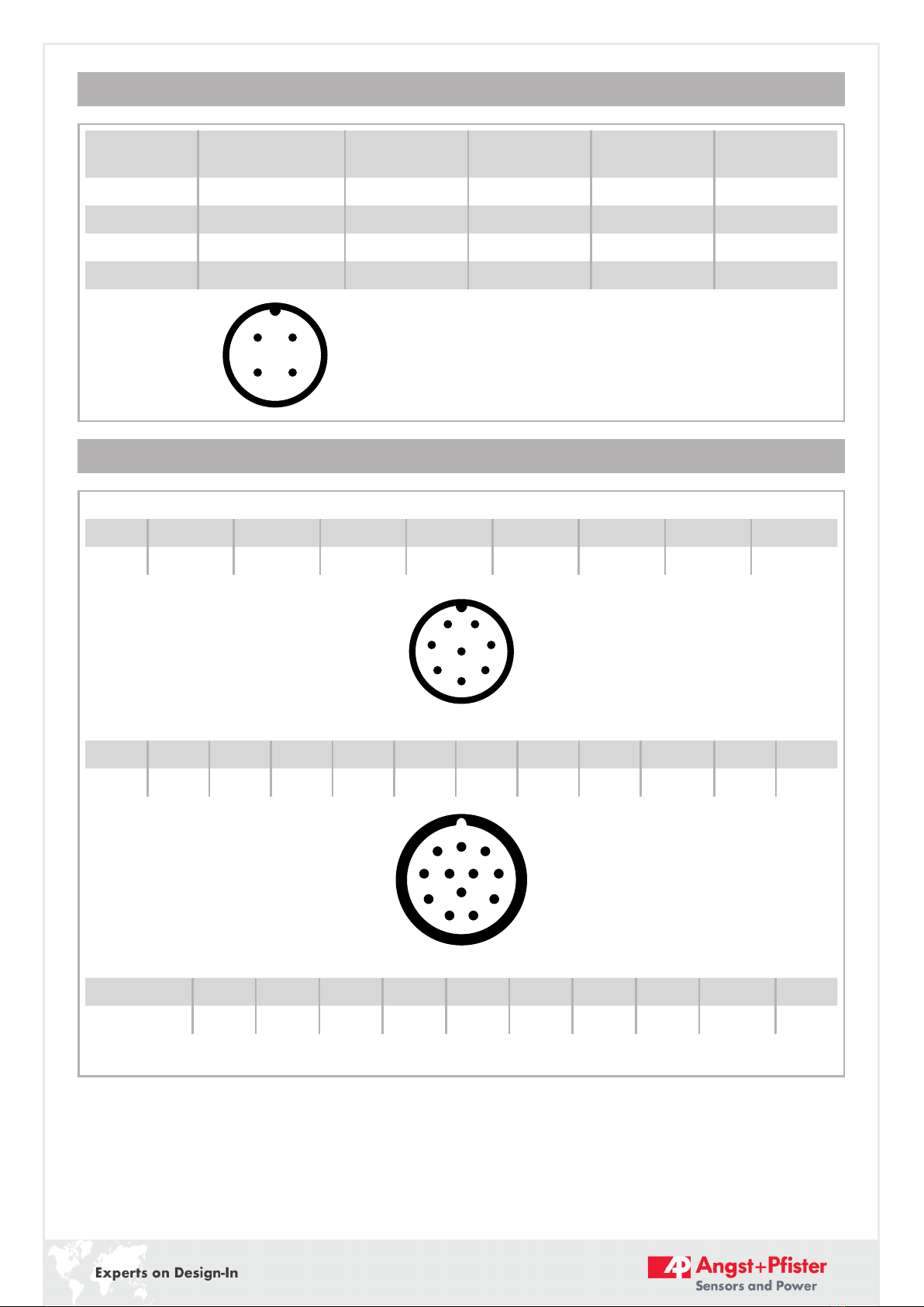
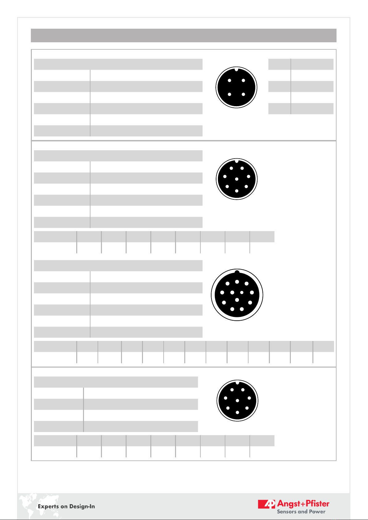
Cable with mating connector M12 (female), 4 poles
K4P2M-S-M12 2 m, straight connector, IP67, shielded
K4P5M-S-M12 5 m, straight connector, IP67, shielded
K4P10M-S-M12 10 m, straight connector, IP67, shielded
K4P2M-SW-M12 2 m, angular connector, IP67, shielded
K4P5M-SW-M12 5 m, angular connector, IP67, shielded
K4P10M-SW-M12 10 m, angular connector, IP67, shielded
Pin Cable colour
1 BN
2 WH
3 BU
4 BK
21
34
Incremental output
Cable with mating connector M12 (female), 8 poles
K8P2M-S-M12 2 m, straight connector, IP67, shielded
K8P5M-S-M12 5 m, straight connector, IP67, shielded
K8P10M-S-M12 10 m, straight connector, IP67, shielded
K8P2M-SW-M12 2 m, angular connector, IP67, shielded
K8P5M-SW-M12 5 m, angular connector, IP67, shielded
K8P10M-SW-M12 10 m, angular connector, IP67, shielded
Pin 12345678
Cable colour WH BN GN YE GY PK BU RD
Cable with mating connector M23 (female), 12 poles
K12P2M-S-M23 2 m, straight connector, IP67, shielded
K12P5M-S-M23 5 m, straight connector, IP67, shielded
K12P10M-S-M23 10 m, straight connector, IP67, shielded
K12P2M-SW-M23 2 m, angular connector, IP67, shielded
K12P5M-SW-M23 5 m, angular connector, IP67, shielded
K12P10M-SW-M23 10 m, angular connector, IP67, shielded
Pin 1 2 3 4 5 6 7 8 9 10 11 12
Cable colour PK RD-BU BU RD GN YE - GY - WH GY-PK BN
21
5
6
7 3
4
8
7
8
4
3
2
6
5
1
9
12
11
10
Digital output SSI:
Cable with mating connector M12 (female), 8 poles
K8P2M-S-M12 2 m, straight connector, IP67, shielded
K8P5M-S-M12 5 m, straight connector, IP67, shielded
K8P10M-S-M12 10 m, straight connector, IP67, shielded
K8P15M-S-M12 15 m, straight connector, IP67, shielded
Pin 12345678
Cable colour WH BN GN YE GY PK BU RD
21
5
6
7 3
4
8