AP&T AP-YV3302H User manual

Electrostatic Sensor
AP-YV3302H
Operating Instruction
Shanghai Anping Static Technology Co., Ltd.
Floor 3, Building 27, No. 69, Guijing Road, Shanghai, China
Tel: 021-64517676
Fax: 021-64517673

AP-YV3302H Electrostatic Sensor
I. Product Overview
AP-YV3302H electrostatic sensor is a detecting instrument developed and produced by Anping Company to
detect the static voltage on the surface of an object with static electricity, which adopts the non-contact
measurement technology to minimize the impact of the detecting instrument on the electrostatic field on the
surface of the object and ensure the accuracy of measurement.
II. Scope ofApplication
It can be widely applied in the industries such as electronics, photoelectricity and plastics.
III. Product Features
1. With comfortable feel and beautiful appearance.
2. Detection distance can be selected via dial switch.
3. Wide detection potential range and high detection precision.
4. Alarm threshold can be set and red light alarm indicatesexceeding threshold.
5. High-definition and all-dimensional LCD data display terminal.
6. Monitoring data can be transmitted to PC in real time.
7. Conformable for operation and convenient for use.
IV. Product Parameters and Technical Functions
1. Performance parameters
1). Technical specifications:

No.
Technical specifications
1
Working voltage
DC8-24V
2
Working current
<20mA
3
Vibration
<1KHz
4
Noise
<5dB
5
Signal output
RS485
NPN (Collector control, 24/100mA)
6
Communication distance
<500m
7
Alarm indication
Red light LED
8
Threshold setting
±100V (default)
9
Alarm range
±50→±5000V
10
Detection angle
<15°
11
Startup stand-by time
5s
12
Infrared control distance
1m
※Due to the improvement and upgrading of the product, the specification and performance of the
product may be changed; Subject to the real product and please understand that notice cannot be given
in advance.
2). The measurement range of static voltage gear and minimum resolution corresponding to each measuring
distance:
Detection
gear
Detection distance
coding
Detection
distance
Measurement
range
Resolution
Measuring
error
1
0
5mm
±2000V
1V
5%
1
10mm
±4000V
2V
2
25mm
±10000V
5V
3
50mm
±15000V
10V
4
100mm
±20000V
10V
5
150mm
±20000V
10V
6
200mm
±20000V
15V
7
250mm
±20000V
20V
2
8
300mm
±20000V
10V
9
350mm
±20000V
15V
A
400mm
±20000V
15V
B
450mm
±20000V
15V
3
C
500mm
±20000V
10V
D
550mm
±20000V
15V
E
600mm
±20000V
15V
F
700mm
±20000V
20V
Notes: the accuracy of the measured static voltage cannot be guaranteed if the detection gear and distance
coding are set incorrectly.
※Due to the improvement and upgrading of the product, the specification and performance of the
product may be changed; Subject to the real product and please understand that notice cannot be given
in advance.

3). Wiring information of network port:
Network port
1. 2
Orange, white and orange
VCC
3
Blue
RS485+B
4
White and blue
RS485+A
5. 6
Green, white and green
GND
7
Brown
TTL-H
8
White and brown
TTL-L
9
Metallic shield shell
PE
※Due to the improvement and upgrading of the product, the specification and performance of the
product may be changed; Subject to the real product and please understand that notice cannot be given
in advance.
4). Technological function of infrared remote control command:
BlowerBar
Sensor
CAL
SRZ
VTH+
VTH-
K-
K+
IB-
IB+
T+ T-
FR/SBR/S
FQ+
FQ-
IB+
IB-
FS+
FS-
RES
For user:
SRZ: reset zero
VTH+/VTH-: threshold adjustment with step unit 10V.
Unlock:
1. After unlocking, 30seconds delay for active if any button is pressed.
2. After unlocking, exit and lock againif there is no any button is pressed within 30 seconds
Explanatory Drawing of Remote Control

2. Prompts of operating technologies:
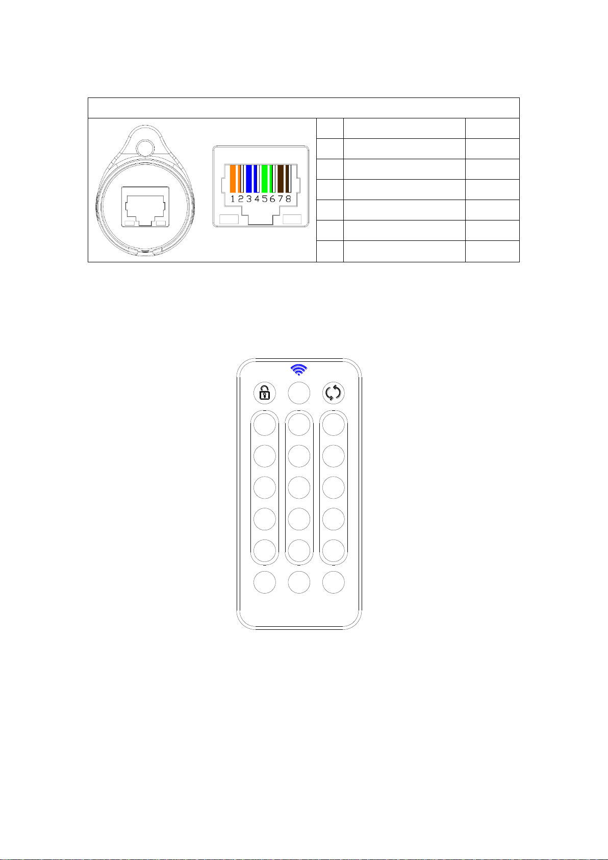
2.1. During operation, align with the front LED of the product (the distance is not more than 1m), press the
unlock key at first, then press the corresponding functional keys to set, and the red light flashes when the key is
pressed.
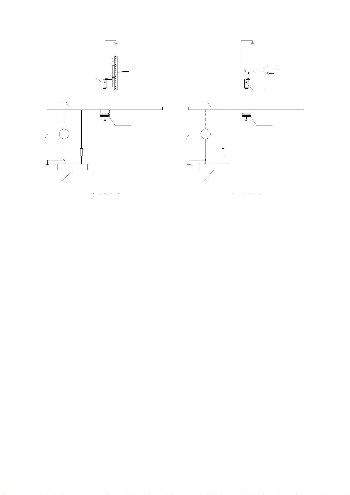
2.2. During zeroing setting, the calibration plate should be much larger than the detection window of sensor, and
the polar plate and sensor should be well grounded.
2.3. During the calibration operation, the calibration plate should be much larger than the detection window of
sensor and the sensor should be well grounded.
2.4. There should be no shield between the sensor and the detected object; otherwise the accuracy of the
detection result will be affected.
2.5. There should be no electrical equipment that may affect the sensor within the detection range of the sensor.
2.6. To accurately measure the charged object, the plane of the sensor detection window must be parallel to the
surface of the detected object.
2.7. When the charged object is smaller than the calibration plate, the measured value will be smaller than the
actual electrostatic value of the charged object.
2.8. When the charged object is larger than the calibration plate, the measured value will be larger than the
actual electrostatic value of the charged object.
2.9. Do not set zero in electrostatic charge state or in the electrostatic measurement process (non-static
calibration process); if zero clearing is made during the electrostatic test, the displayed electrostatic value will
be zero.
2.10. Influence of temperature and humidity on electrostatic detection:
The lower the temperature is, the smaller the humidity is, the less water is contained in the space, and the
more easily the surrounding object triboelectric and the greater the interference to the electrostatic
detection is.
1) The higher the temperature is, the higher the humidity is, the more water is contained in the space,
and the more active the movement of water molecules is, which is easy to produce corona or spark
discharge to the calibration device and the greater the influence on the uniform electric field generated by
the calibration device, the weaker the uniform electric field will be.
2) Under the same humidity, the lower the temperature is, the less water is contained in the space, and
the more easily the surrounding object triboelectric and the greater the influence on the electrostatic
detection is.
Therefore, during electrostatic calibration/detection, the environmental temperature and humidity should be
clearly indicated during calibration/detection.
2.11. Due to the existence of the cosmic rays and micro-radioactive substance in the environment as well as the
use of various kinds of electrical equipment, there are inevitably more or less positive and negative irons in the
detection space, which may also have certain impact on the detection results.
3.Display information of monitoring terminal
Working status: whether the sensor works normally and has alarm output.
Equipment address: display the address set by the sensor.
Detection distance: display the detection distance set by the sensor.
Threshold voltage: display the set safety (alarm) threshold of static voltage.
Real time voltage: display the static voltage value on the surface of the measured object.

IMS Smart Controller
WAN/LAN P4
P3P2P1 POWER
P1-P4 : 1/2-VCC 3-RS485_B 4-RS485_A 5/6-GND 7-C_VTH/HVAL 8-C_ACT/Clean 9-PE(Metal shield)
P1 P2
P4
P3
Red-VTH/HVAL ACT/Clean-Green ACTWrok/Link
NEXT
SCAN
NEXT
LINK
B
SET
S
SCROLL
T
RJ45端口
液晶显示屏
2.4G通讯天线
静电传感器监测设置 静电消除器监测设置
静电消除器运行时间设置
无线连接 温湿度显示
WAN/LAN:
以太网连接端口
POWER:监控器电源接口
(附带RS485通信)
P1→P4:消电器或传感器
工作状态监控及供电端口
M4安装孔 温湿度探测窗口
ACT:监控器上电指示,绿灯长亮
Wrok/Link:
网络接通:红灯闪烁,长亮绿灯,
网络断开:红灯闪烁,绿灯熄灭
P1→P4:4路状态指示灯
红灯闪烁:传感器阈值报警/消电器高压报警
绿灯长亮:传感器/消电器上电指示
绿灯闪烁:消电器清洁指示
M4 mounting hole
Temperature and humidity
detection window
2.4G communication antenna
Wireless connection
Temperature and humidity
display
LCD
Monitoring setting of
electrostatic sensor
Setting of operating time of
electrostatic eliminator
Monitoring setting of electrostatic
eliminator
ACI: AC indication on monitor, green light is ON for
long
Network connection: red light flashes and
green light is ON for long
Network disconnection: red light flashes and
green light is OFF.
4-line status indicator light
Red light flashes: threshold alarm of sensor, high voltage alarm of static eliminator
Green light is ON for long: sensor and eliminatorpower on indication
Green light flashes: static eliminatorcleaning indication
Power port of monitor
(attached with RS485 communication)
RJ45 port
Ethernet connection port
Working status monitoring and
power supply port of eliminator or
sensor
Work/Link:

4. Mechanical parameters
①Mechanical parameters of sensor:
Overall dimension: <44*33*85mm (L*W*H)
Net weight: about 49.7g
The overall dimension of sensor is shown as follows:
②Mechanical parameters of monitoring terminal
Overall dimension: 100*120*25mm (L*W*H)
Net weight of monitoring terminal: about 400g
The overall dimension of monitoring terminal is shown as follows:
100
120
52
76
87.5
14
14 4
25
IMS Smart Controller
WAN/LAN P4P3P2P1 POWER
P1-P4 : 1/2-VCC 3-RS485_B 4-RS485_A 5/6-GND 7-C_V TH/HVAL 8-C_ACT/Clean 9-PE(Metal shield)
P1 P2
P4
P3
Red-VTH/HVAL ACT/Clean-Green ACTWrok/Link
NEXT
SCAN
NEXT
LINK
B
SET
S
SCROLL
T

③Mechanical parameters of power adapter:
Overall dimension: 124*61*40mm (L*W*H)
Net weight of power adapter: about 234g
The overall dimension of power adapter is shown as follows:
输出端口
(24V直流1/2线输出) 三相电源插座
(AC100-240V,50/60Hz)
④Mechanical parameters of communication converter:
Overall dimension: <90*28*22mm (L*W*H)
Net weight of communication converter: about 20.5g
The overall dimension of communication converter is shown as follows:
接口
接口
RJ45 output port
(24V DC 1/2 line output)
Three-phase power socket
RJ45 port
USB port

⑤Mechanical parameters of system integrated power supply:
Overall dimension: 380*160*50mm (L*W*H)
Net weight of terminal power supply: about 2500g
The overall dimension of terminal power supply is shown as follows:
380 160
SW1
P1P2P3P6 P5 P4P7P8P10 P9P11P13 P12P15P16 P14
P30P32 P31 P28P29 P27 P26 P25 P17
P18P19
P21 P20P23
P24 P22
DC_24VPLCRS485WAN/LAN
P1-P32 : 1/2-VCC 3-RS485_B 4-RS485_A 5/6-GND 7-C_VTH/HVAL 8-C_ACT/Clean 9-PE(Metal shield) AC
Red-VTH/HVAL ACT/Clean-Green
SW2 SW4SW3 SW5 SW6 SW10SW8 SW9SW7 SW11 SW13SW12 SW14 SW15 SW16
P1
P17 P18
P2 P4P3
P20P19
P7 P8P6P5
P23 P24P22P21 P29 P30 P32P31
P27 P28P26P25
P9 P10 P12P11 P15 P16P14P13
V/A Display
IMS Power Supply
Link Work RXTX ACTTX RX 50
8-M4安装孔
V. Working Environment
Working temperature: 0℃→+50℃
Working humidity: 30→65%RH
VI. Product Calibration
1. Calibration environmental conditions
The calibration environmental conditions and requirements are as follows:
a) Environmental temperature: 20℃±5 ℃
b) Relative humidity: 30-60%
c) There is no measurable electrical field, magnetic field as well as positive and negative irons around.
d) There is ground wire and the resistance of ground is <100Ω.
2. Equipment for calibration
The instrument and equipment for calibration should be calibrated by the institution of metrological
technology, which should meet calibration use requirements within the validity period.
The main calibration equipment mainly consists of DC high voltage meter, DC high voltage power supply,
standard plate electrode and distance regulator, etc. The sensor is placed on the central line of the
calibration plate and the block diagram of the calibration device for the non-contact electrostaticvoltmeter
is shown as follows:
8-M4 mounting hole

KV
R
Rd
D1
D2
D3
S1
C
S2
S3
S2
S3
C
KV
R
Rd
D1
D2
D3
S1
垂直测试 水平测试
The requirements for the equipment and device are as follows:
C——calibrated product: electrostatic sensor
D1——DC high voltage power supply: output range is -20KV~+20KV, continuously adjustable, or the
minimum stepping is 10V, and measurement uncertainty is less than 1/4 of the allowable error limit of the
calibration table.
D2——DC high voltage meter: measurement range is -40KV~+40KV and the measurement uncertainty is less
than 1/4 of the allowable error limit of the calibration table.
D3——standard plate electrode: the plate electrode should be circular or square rounded corner. It’s appropriate
that the radius of curvature on the edge of the electrodes does not generate corona and it’s recommended that
the edges of the electrodes should be wrapped with insulating materials; the plate area should be large enough
and the diameter or side length should be no less than 0.4m. Our calibration plate is square stainless steel plate
with the dimension of 600mm*600mm.
R
——protective resistance: the withstand voltage strength of resistance is 20KV and the current through the
protective resistance and human body is <5mA and the resistance value R conform to the following formula
requirement:
/ 0.1%
d
R R R( )
Where:
R
is protective resistance and the unit is Ohm (Ω);
d
R
is the resistance of insulating support and the unit is Ohm (Ω); resistance value
d
R
>
1013Ωand the withstand voltage strength is >25KV.
The above two kinds of resistance may cause different static voltage values in detection under the same
standard voltage due to the different resistance values.
S1——insulating support
S2——graduated scale, the measurement range is 0mm~750mm and the measurement uncertainty is less than
0.5mm.
Vertical test
Horizontal test

S3——distance regulator: the sensor should be placed on the calibration device to extend out the front end. The
geometrical shape and materials of the support should minimize the impact on the distribution of the electrical
field around the front end of the sensor.
VII. Product Performance
The test data of the standard plate electrode is as follows:
The static voltage values under 3 groups of test distances were detected. The standard plate electrode was
600mm*600mm stainless steel electrode. The test distance was the distancebetween the surface of plastic
shell to that of the plate electrode on one side of the detection window of the electrostatic sensor. The light
grey heavy line in the figure is the calibration voltage line when the slope is 1.
-10000 -5000 0 5000 10000
-10000
-5000
0
5000
10000 标 准 电压( 斜 率K=1)
测试距离100mm
测试距离300mm
测试距离500mm
实测电压值( V)
标 准 平板 电压值( V)
-1000 -800 -600 -400 -200 0 200 400 600 800 1000
-1000
-800
-600
-400
-200
0
200
400
600
800
1000
实测电压值( V)
标 准 平板 电压值( V)
标 准 电压( 斜 率K=1)
测试距离100mm
测试距离300mm
测试距离500mm
The following two figures are the test data maps under different horizontal test distances when the vertical
test distance is 500mm, standard plate electrode is 600mm*600mm stainless steel electrode and the sensor is
relative to the central position of the detection plate:
Standard voltage (slope K =1)
Test distance 100mm
Test distance 300mm
Test distance 500mm
Actual measured voltage value
Voltage value of standard plate
Standard voltage (slope K =1)
Test distance 100mm
Test distance 300mm
Test distance 500mm
Actual measured voltage value
Voltage value of standard plate

-300 -200 -100 0 100 200 300
-12000
-10000
-8000
-6000
-4000
-2000
0
2000
4000
6000
8000
10000
垂直 测试距离500mm
实际测试电压值( V)
水平测试距离( mm)
-300 -200 -100 0 100 200 300
-1200
-1000
-800
-600
-400
-200
0
200
400
600
800
1000
1200
实际测试电压值( V)
水平测试距离( mm)
垂直 测试距离500mm
VIII. Operation and precautions
1. Instructions for use:
During use, the plane of the sensor electrostatic detection window should be parallel to the surface of the
object under test. The detection distance and detection gear should be selected according to the static
electricity quantity and the operating environmentof the charged object (i.e. above mentioned standard
detection distance: 5mm, 10mm, 25mm, 50mm, 100mm, 150mm, 200mm, 250mm, 300mm, 350mm,
400mm, 450mm, 500mm, 550mm, 600mm, 700mm); at this point, the detection data displayed by the
terminal is the most accurate.
Vertical test distance 500mm
Actual measured voltage value
Horizontal test distance
Baseline Voltage
Baseline Voltage
Baseline Voltage
Baseline Voltage
Baseline Voltage
Baseline Voltage
Baseline Voltage
Baseline Voltage
Baseline Voltage
Baseline Voltage
Baseline Voltage
Baseline Voltage
Baseline Voltage
Baseline Voltage
Baseline Voltage
Baseline Voltage
Baseline Voltage
Baseline Voltage
Baseline Voltage
Baseline Voltage
Baseline Voltage
Baseline Voltage
Baseline Voltage
Baseline Voltage
Baseline Voltage
Baseline Voltage
Baseline Voltage
Baseline Voltage
Baseline Voltage
Baseline Voltage
Baseline Voltage
Baseline Voltage
Vertical test distance
Actual measured voltage value
Horizontal test distance

2. On-line mode: (Monitoring terminal, integrated power supply and communication software need to be
purchased additionally)
For the power output network port, monitoring terminal network port and electrostatic sensor network port
of 24V power adapter, the network ports of the three devices are both the power port and the communication
port, and the network ports of the three devices can be commonly used.
1)Connection with monitoring terminal:
IMS Smart Controller
WAN/LAN P4
P3P2P1 POWER
P1-P4 : 1/2-VCC 3-RS485_B 4-RS485_A 5/6-GND 7-C_VTH/HVAL 8-C_ACT/Clean 9-PE(Metal shield)
P1 P2
P4P3
Red-VTH/HVAL ACT/Clean-Green ACTWrok/Link
NEXT
SCAN
NEXT
LINK
B
SET
S
SCROLL
T
接AC
电源
网线
网线
手持终端
网口适配器
静电传感器
2)Connection with PC:
SW1
Red-VTH/HVAL ACT/Clean-Green
SW2 SW4SW3 SW5 SW6 SW10SW8 SW9SW7 SW11 SW13SW12 SW14 SW15 SW16
P1
P17 P18
P2 P4P3
P20P19
P7 P8P6P5
P23 P24P22P21 P29 P30 P32P31P27 P28P26P25
P9 P10 P12P11 P15 P16P14P13
V/A Display
IMS Power Supply
PC
一个串口可连接16台机器
静电传感器 静电传感器静电传感器
转
通讯转换器
终端电源
网线
网线
3. Operating steps (refer to the following attached drawings):
①According to the static electricity quantity and the operating environmentof the charged object, rotate the
circular dial switch with the 3mmdiameter cross screwdriver to select the test distance.
②According to the static electricity quantity and the operating environmentof the charged object, turn the bar
dial switch and select the detection gear.
③According to withstand static voltage value of the protected product, set the safety (alarm) threshold of static
electricity via the remote controller or monitoring software.
Notes: when the detected static voltage value is within the set threshold of static electricity, the threshold
alarm indicator light is green, and it will be red if the set threshold is exceeded.
Hand-held terminal
Network cable
Network cable
Electrostatic sensor
Internet access adapter
Connect with AC100-240V
50/60Hz power supply
Terminal power supply
Network cable
Network cable
Electrostatic sensor
RJ45 to USB
communication converter
One serial port can be
connected with 16 sets of
machines

④According to the production station, rotate the circular dial switch with the 3mmdiameter cross screwdriver
to set the equipment address.
4. Installation drawing:
Select test
distance
Static
threshold
alarm
indicator
light
Select
equipment
address
Select
measurement
range for test

4.1. Structure chart of each mounting fixture:

4.2. Structure chart of fastenings for mounting stem:
4.3. Schematic Diagram for Installed Location:
被测物体
φ直径不锈钢安装杆
圆头滚花纹十字槽
手拧螺丝M4*8
垂直安装于被测物体
5. Precautions for Installation and Use:
5.1. Precautions:
To correctly use the equipment, please carefully read the operating instructions before use.
Before power on, please check the specification of the provided power supply. Any power supply
nonconforming to the specification will cause damage and even failure of product.
Please operate the product under the specified temperature (0~50℃).
During test, the distance between the person and the product should be more than 1m to avoid
Φ5 diameter stainless steel mounting stem
Round head knurled cross groove
Thumb screwM4*8
Vertically installed on the tested object
Tested object

impact on test by static electricity on human body; the tester must wear anti-static clothing,
anti-static hat and anti-static shoes.
The insertion depth of the φ5 diameter stainless steel mounting stem should not exceed the position
of the detection gear switch on the back of the sensor.
The surface of the φ5 diameter stainless steel mounting stem should have no insulation coating.
During detection, please don’t touch the electrostatic detection probe.
Ensure that the part of the sensor window is not polluted by particles and dust.
There should be no shield between the sensor and the detected object; otherwise the accuracy of the
detection result will be affected.
There should be no electrical equipment that affects the sensor within the detection range of the
sensor; otherwise, failure and damage may be caused to the internal equipment and chip.
To accurately measure the charged object, the plane of the sensor detection window must be parallel
to the surface of the object being measured.
Connect power supply for 5s before use; otherwise the data display may be unstable sometimes.
When the charged object is smaller than the calibration plate, the measured value will be smaller
than the actual static value of the charged object.
When the charged object is larger than the calibration plate, the measured value will be larger than
the actual static value of the charged object.
Don’t set zero under static charge state or in static measurement process (non-static calibration
process); if zero is set during static measurement, the displayed static value may be zero.
Don’t install high voltage equipment around, such as high voltage power supply, electrostatic
generator, iron generator and eliminator, because the high voltage will affect the performance and
detection accuracy of the sensor.
During the installation of high vibration area, please fasten the sensor, otherwise data error may
occur.
Please regularly check the power cable/communication cable of the product and replace it
immediately if there is damage, otherwise problems such as electric leakage, poor communication
and abnormal work may be caused.
If the product suffers mechanical impact such as drop, collision and so on, it may cause failure.
5.2. Warnings:
The whole set of equipment must be reliably grounded during use; otherwise abnormality and even
damage may be caused to the sensor.
It’s forbidden to use the equipment in flammable and explosive environment.
It’s forbidden to touch the electrostatic detection window with sharp object.
The product is strictly prohibited to contact water stain; otherwise abnormality will be caused, thus
leading to electric shock or fire.
If the measurement range of detection is exceeded, it may cause product failure.
During the inspection or replacement of product, turn off power, otherwise electric shock or fire may
be caused.
This detection instrument is a precision device, please don’t dismantle it.
It’s forbidden to dismantle the product arbitrarily; internal maintenance and repair must be made
by professional personnel.
The product is specially designed for detecting static electricity on the surface of the object. It is
strictly prohibited to be used for other purposes. Any abnormal use may cause machine failure,
electric shock, fire and other hidden dangers.

6. Failure analysis
NO
Fault occurred
Possible cause
Solution
1
Power port indicator
light is not ON
Bad contact of power cable
Confirm whether the power cable is good and connected stably.
Incorrect connection of power cable
Confirm whether the power cable is connected correctly.
Mismatching of power supply
Confirm the specification and model of power supply
(INPUT:100—240VAC 50/60Hz; OUTPUT: 24VDC 2000mA)
2
Detected static voltage
value is abnormal or the
error is too big
Bad grounding of sensor
Confirm whether the sensor is well grounded.
There is high voltage equipment,
ionization device or strong
electromagnetic equipment around the
sensor
Remove the high voltage equipment, ionization device or strong
electromagnetic equipment.
Incorrect setting of measurement range
gear or detection distance
Refer to the gear and measurement range setting table.
Improper setting of installation location
of sensor
Confirm correct installation location and refer to the operation and
use precautions.
3
Green threshold alarm
indicator light is not
ON
——
Return to the manufacturer for repair.
4
Red threshold alarm
indicator light is not
ON
The set static threshold value is big or
exceeds the measurement range
According to the working environment and static control
requirements, refer to the gear and measurement range setting table
to reasonably determine the static alarm threshold.
5
Abnormal smell of
product
Burning damage of components and
parts
Return to the manufacturer for repair.
6
If there are other unlisted problems or the problems still cannot be solved by the above solutions, please contact the manufacturer or
seller.
IX. Maintenance
1. To ensure the good performance of the product, please store the equipment in a dry place away from light
when it’s not used. Please don’t press it heavily.
2. This equipment is a precision detector; please don’t vibrate it intensively during use.
X. After-sales Services
AP-YV3302H electrostatic sensor has received strict testing, inspection and aging treatment before delivery,
and its performance can completely reach the relevant indicators specified in the operating instructions. AP&T
makes the following commitments to the customer: repair or replace any defective parts free of charge after the
inspection by our company from the date of purchase within one year. However, this commitment shall not
apply to:
1. The equipment is used incorrectly;
2. Damage caused by negligence or accident during use;
3. Change or dismantle the product arbitrarily or the product has been repaired by other service department not
authorized by Shanghai AnpingStatic Technology Co., Ltd.
4. Failure caused by external factors such as fire, earthquake, flood and abnormal voltage.
Except for the repair or replacement of the parts within the provision, AP&T shall not assume any obligations
unrelated to this and shall not be liable to the user of the product.
XI. Packing Accessories
1. Certificate ×1 2. Warranty Card ×1 3. Operating Instruction ×1 4. Power adapter ×1
5.1.8m Power network cable ×1 6. International three-phase power cable ×1 7. IR remote control ×1
8. M4*8 round head knurled cross groove thumb regulating screw ×1
9. Dial switch rotation screwdriver ×1 (including straight screwdriver×1 , cross screwdriver ×2)
10. Installed package: 500mm length φ5 diameter stainless steel mounting stem ×1 , anodic oxidation (black)
20×20 four - sided slot industrial aluminum profiles, mounting fixture ×3 , support fastenings ×1, M5 round
head hexagon socket screw ×3 , M5 hexagon socket screw with large flat head, M5 slider nut ×5
Table of contents
Other AP&T Accessories manuals
Popular Accessories manuals by other brands

Held
Held Helite user guide

Lightolier
Lightolier Lytespan 8676B specification

La Crosse Technology
La Crosse Technology TX-63U-IT instruction manual

Pepperl+Fuchs
Pepperl+Fuchs LUC-M10 Safety instructions

Allen-Bradley
Allen-Bradley Rockwell Automation VisiSight 42JT installation instructions

Chamberlain
Chamberlain SWG-0500 installation instructions