AP&T AP-YV3303 User manual

Intelligent Electrostatic Sensor
AP-YV3303
AP&T
R(The second generation)Shanghai Anping Static Technology Co.,Ltd
Intelligent Electrostatic Sensor
AP&T

The electrostatic safety (alarm) threshold can be set by remote control or monitoring
software. The red light will alarm if the threshold is exceeded while the threshold
alarm indicator will be green if the threshold is within the electrostatic threshold,
Intelligent Set the electrostatic alarm threshold
It can be installed and fixed above the object to be detected and detect the static
electricity in real time.
Online Detect static electricity online automatically
The detection distance can be selected by the DIP switch.
Adjustable Detection distance
A closed-loop monitoring and elimination system is formed by electrostatic sensing
detection equipment, electrostatic elimination equipment, power supply equipment,
display equipment and IMS (ionization monitoring system) to realize automatic and
unmanned electrostatic monitoring and elimination.
Closed loop Static electricity detection, monitoring, elimination
The monitoring data is transmitted to the PC in real time, which can realize data storage
and data collection.
Network Monitoring data is transmitted to PC in real time
Using non-contact vibration capacitance electrostatic detection technology ...

Difficult to record paperless
ESD cannot be monitored online in real time
Data cannot be centrally managed
Unable to link alarm abnormally
Unable to control the source
Reduce people and increase efficiency
Online monitoring linkage control
Seamless connection with open protocols
Low power consumption, environmental
protection and energy saving
Systematize online intelligent monitoring
Traceability to the source of non-
performing rate
Electrostatic sensor Electrostatic eliminator
Handheld terminal
PC terminal
elimination equipment
closed-loop electrostatic monitoring
and elimination system
Terminal power
Closed-loop electrostatic detection, monitoring and elimination system ...
The closed-loop electrostatic monitoring and elimination system, formed by detection equipment, elimination equipment, power supply equipment,
display equipment and IMS (Ionization Monitoring System), can realize real-time monitoring, data storage, and dynamic display under the control of
system software to solve the long-term recording problems of electrostatic monitoring and data collection, which can be customized and developed
according to the individual needs of customers, truly achieve increased production capacity, improved efficiency, automatic and intelligent
electrostatic monitoring.
Human VS Machine
detection equipment power supply equipment
display equipment

Product specifications and technical functions
1)Technical Specifications:
Specification one
NO. Basic parameter
1 Working voltage DC8-24V
2 Working current < 50mA
3 Sampling time About 1ms
4 Vibration < 1KHz
5 Noise < 5dB
6 Signal output RS485(115200bps,8,1,n,n)(≧ 20ms)
Collector open circuit(<50V/100mA)
7Network port definition
1、2345、6、97 8
White-orange/orange White-blue Blue White-green/green White-brown Brown
VCC RS485_B RS485_A GND、PE NPN-C1 NPN-C2
8 Communication distance < 300m
9 Alarm indication LED
10 Threshold setting range 0 ~ ±5000V
11 Detection angle < 15°
12 Test plate size 600mm*600mm
13 Startup test time 5S
14 Infrared controlled range < 20°,1m
※ Product specifications and performance may be changed due to product improvements and upgrades. Please refer to the actual product without prior notice.
2) The static voltage range and minimum resolution corresponding to each detection distance:
Specification two
Detection
gear Distance
coding Detection
distance Range Resolution Error Zero runout Calibration
10 5mm ±2000V 1V
10%
±1V
×
1 10mm ±4000V 2V ±2V
22 25mm ±20000V 10V ±10V
3 50mm ±20000V 10V ±10V
34 100mm ±20000V 10V ±10V √
5 150mm ±20000V 10V ±10V
×
46 200mm ±20000V 10V ±10V
7 250mm ±20000V 10V ±10V
58 300mm ±20000V 10V ±10V √
9 350mm ±20000V 10V ±10V
×
6A 400mm ±20000V 10V ±10V
B 450mm ±20000V 10V ±10V
7C 500mm ±20000V 10V ±10V √
D 550mm ±20000V 10V ±10V
×
8E 600mm ±20000V 10V ±10V
F 700mm ±20000V 10V ±10V
※ Product specifications and performance may be changed due to product improvements and upgrades. Please refer to the actual product without prior notice.
Unlock (unlock before debugging)
Customer use
SRZ:reset
VTH+/VTH-:Threshold adjustment in 10V unit
30s delay if any key is pressed after unlocking
Exit and re-locked if no key is pressed after unlocking
Product specifications and technical functions ...
3)Infrared remote control command
technology function:

Product Operation Technical Tips
Monitor terminal display information
•There will inevitably be more or less positive and negative ions in the detection space which will also have a certain impact on the detection results
due to the existence of cosmic rays, trace radioactive substances in the environment, and the use of various electrical equipment.
Working status: monitor whether the sensor is working normally and alarm output
Equipment Address: Display the address set by the sensor
Detection distance: Display the detection distance set by the electrostatic sensor
Threshold voltage: Displays the set static voltage safety (alarm) threshold
Real-time voltage: display the static voltage value on the surface of the measured object
IMS Smart Controller
P3P2
WAN/LAN P1 P4 POWER
P1-P4 : 1/2-VCC 3-RS485_B 4-RS485_A 5/6-GND 7-C_VTH/HVAL 8-C_ACT/Clean 9-PE(Metal shield)
P1 P2
P4
P3
Red-VTH/HVAL ACT/Clean-Green ACTWork/Link
NEXT
SCAN
NEXT
LINK
B
SET
S
SCROLL
T
RJ45 port
2.4G communication antenna
Wireless connection
WAN/LAN:
Ethernet connection port
M4 mounting holes Temperature and humidity detection window
•Aim at the LED on the front of the product during operation (the distance should not exceed 1m), first press the unlock key, and then press the
corresponding function key to set, the red light flashes when the key is pressed.
• The calibration plate should be much larger than the sensor detection window, and the plate and sensor should be well grounded when performing
zero adjustment.
•The calibration plate should be much larger than the sensor detection window, and the sensor should be well grounded when performing calibration.
•There should be no obstruction between the sensor and the detected object, otherwise the accuracy of the detection result will be affected.
•There should be no electrical equipment that may affect the sensor within the detection distance of the sensor.
•The plane of the sensor detection window must be parallel to the surface of the object to be measured to accurately measure charged objects.
•The measured value is smaller than the actual electrostatic value of the charged object when the charged object is smaller than the calibration plate.
•The measured value is larger than the actual electrostatic value of the charged object when the charged object is larger than the calibration plate.
•Do not adjust zero in the static charge state or in the electrostatic detection process (Non-electrostatic calibration process); the displayed static value
will be zero if reset it during static electricity testing.
•Influence of temperature and humidity on electrostatic detection:
①The lower the temperature, the lower the humidity, the less moisture in the space, the easier the surrounding objects are to be electrified by
friction, and the greater the interference to electrostatic detection.
②The higher the temperature, the higher the humidity, the more moisture in the space, the more active the movement of water molecules, the more
easily the calibration device generates corona or spark discharges, and the greater the impact on the uniform electric field generated by the
calibration device which will weaken the uniform electric field.
③The lower the temperature, the less moisture in the space, the easier the surrounding objects are to be electrified by friction, and the greater the
impact on electrostatic detection under the same humidity.
Therefore, the ambient temperature and humidity during calibration/testing should be clearly marked when doing electrostatic calibration/testing.
LCD
Electrostatic sensor monitoring settings
Temperature and humidity display
Wrok/Link:
Network connection:red light flashing, green light always on
Network disconnection:red light flashing, green light is off
Electrostatic eliminator running time setting
Electrostatic eliminator monitoring settings
ACT:Monitor power-on indication, green light always on
P1→P4:4 ways status indicator light
Red light flashing: Sensor threshold alarm/eliminator high voltage alarm
Green light always on: Sensor/eliminator power-on indication
Green light flashing: Eliminator cleaning indication
POWER:Monitor power port
(with RS485 communication)
P1→P4:The working status monitoring and
power supply port of the eliminator or sensor

Mechanical parameters
① Sensor mechanical parameters:
Dimensions:< 44*33*85mm(L*W*H)
Net weight:about 49.7g
The external dimension of the sensor is as follows:
② Monitoring terminal mechanical parameters:
Dimensions:102*28.5*22mm(L*W*H)
Monitoring terminal net weight:about 400g
The external dimension of the monitoring terminal is as
follows:
③ Adapter power mechanical parameters:
Dimensions:124*61*40mm(L*W*H)
Adapter power net weight:about 234g
The external dimension of the adapter power is as follows:
⑤System integrated power supply mechanical parameters:
Dimensions:380*160*50mm(L*W*H)
System integrated power supply net weight:about 2500g
The external dimension of the system integrated power supply is as
follows:
④ Communication converter mechanical Parameters:
Dimensions:< 90*28*22mm(L*W*H)
Communication converter net weight:about 20.5g
The external dimension of the communication converter
is as follows:
Nut Post
100
120
52
76
87.5
14
14 4
25
IMS Smart Controller
WAN/LANP4P3P2P1 POWER
P1-P4 : 1/2-VCC 3-RS485_B 4-RS485_A 5/6-GND 7-C_V
TH
/HV
AL
8-C_ACT/Clean 9-PE(Metal shield)
P1 P2
P4
P3
Red-V
TH
/HV
AL
ACT/Clean-Green ACTWork/Link
NEXT
SCAN
NEXT
LINK
B
SET
S
SCROLL
T
output port
(24V DC 1/2 line output)
Three-phase power socket
(AC100-240V,50/60Hz)
port
port
380 160
SW1
P1P2P3P6 P5 P4P7P8P10P 9P11P13P 12P15P16P 14
P30P32P 31 P28P29 P27 P26P 25 P17
P18P19
P21 P20P23
P24P 22
DC_24VPLCRS485WAN/LAN
P1-P32 : 1/2-VCC 3-RS485_B 4-RS485_A 5/6-GND 7-C_V
TH
/HV
AL
8-C_ACT/Clean 9-PE(Metal shield)A C
Red-V
TH
/HV
AL
ACT/Clean-Green
SW2S W4SW3S W5 SW6S W10SW8S W9SW7S W11S W13SW12 SW14 SW15 SW16
P1
P17 P18
P2 P4P3
P20P19
P7 P8P6P5
P23 P24P22P21 P29P 30 P32P31
P27 P28P26P25
P9 P10P 12P11P 15 P16P14P13
V/A Display
IMS Power Supply
Link Work RXTX ACTTX RX
50
8-M4
mounting holes

The instruments and equipment used for calibration must be calibrated by a metrological technical institution, meet the requirements for calibration
use, and be within the validity period.
The calibration equipment is mainly composed of: DC high voltage meter, DC high voltage power supply, standard plate electrode, distance regulator
and so on. The sensor is located on the center line of the calibration plate, and the block diagram of the non-contact electrostatic voltmeter calibration
device is as follows:
The equipment and device requirements are as follows:
C——calibrated product: electrostatic sensor;
D1——DC high voltage power supply: the output range is -20KV ~ +20KV, continuously adjustable, or the minimum step is 10V, and the
measurement uncertainty is less than 1/4 of the allowable error limit of the calibrated meter;
D2——DC high voltage meter: the measurement range is -40KV ~ +40KV, and the measurement uncertainty is less than 1/4 of the allowable error
limit of the calibrated meter;
D3——Standard plate electrode: the plate electrode should be round or square with rounded corners, and the radius of curvature of the electrode edge
should not cause corona phenomenon; the area of the plate should be large enough, and the diameter or side length should not be less than 0.4m. The
size of our calibration plate is 600mm*600mm square stainless steel plate.
R——Protection resistance: The withstand voltage of the resistance should be > 20KV, the current passing through the protection resistance and the
human body should be < 5mA, and the resistance value should meet the requirements of the following formula:
In the formula: R is the protection resistance, the unit is ohm (Ω);
Rd is the resistance of the insulating support, the unit is ohm (Ω), the resistance value is > 1013Ω, and the withstand voltage is > 25KV.
The different resistance values of the above two resistors may result in different static voltage values detected under the same standard voltage
S1——Insulation bracket.
S2——Scale, measuring range: 0mm ~ 750mm, measurement uncertainty less than 0.5mm.
S3——Distance regulator: The sensor is placed on the calibration device with the front end of the sensor extending. The geometry and material of the
bracket should minimize the effect on the electric field distribution around the front end of the sensor.
R/(R+Rd) < 0.1%
Calibration environmental conditions
Calibration equipment
The calibration environmental conditions and requirements are as follows:
NO. Contents Model and parameters
1High voltage
power supply BERTAN_205B-20R
2 Plate Material: stainless steel, thickness: 1mm, length and width: 600mm*600mm
3 Environment Dust-free room, temperature: 20°C—23°C, humidity: 40 ﹪ RH—45 ﹪ RH, there
is no measurable electric field, magnetic field, positive and negative ions around
4 Device The same standard device on both sides; ground wire, and theground wire
resistance is less than 1Ω
KV
Rd
D1
D2
D3
S1
C
S2
S3 S2
S3
KV
R
Rd
D1
D2
D3
S1
Vertical test horizontal test
C
Product calibration ...

The static voltage values under 3 sets of test distances are detected. The standard plate electrode is 600mm*600mm stainless steel electrode. The test
distance is the distance between the surface of the plastic shell and the surface of the calibration plate electrode on the side of the electrostatic sensor
detection window (the sensor was located directly above the center point of the calibration electrode). The light gray thick solid line in Figure 10
below is the calibration voltage line with a slope equal to 1. This calibration line is a virtual line, which is designed to mark the ideal situation where
the measured voltage value of the sensor is exactly the same as the voltage value applied by the standard plate.
Figure 10-1 Vertical test data chart of standard plate electrode Figure 10-2 Vertical test data chart of standard plate electrode
The test is divided into vertical test and horizontal test. The schematic diagram 9 of the sensor test device is as follows:
The vertical test data of the sensor and the standard plate electrode are as follows:
-10000 -50000 5000 10000
-10000
-5000
0
5000
10000
Standard voltage(slopeK=1)
Test distance100mm
Test distance300mm
Test distance500mm
The measured voltage value of the sensor(V)
The voltage value applied by the standard plate(V)
-1000 -800 -600 -400 -200 0 200 400 600 800 1000
-1000
-800
-600
-400
-200
0
200
400
600
800
1000
Figure 9 Schematic diagram of the sensor testing device
KV
R-Current limiting protection resistor
Rd
D1-High voltage power supply
D2-High pressure gauge
D3-calibration electrode
S1-Insulation bracket
X
ZElectrostatic sensor
Product testing performance testing ...
The measured voltage value of the sensor(V)
The voltage value applied by the standard plate(V)
Standard voltage(slopeK=1)
Test distance100mm
Test distance300mm
Test distance500mm

Calibration plate voltage-0V
Calibration plate voltage-100V
Calibration plate voltage-200V
Calibration plate voltage-300V
Calibration plate voltage-400V
Calibration plate voltage-500V
Calibration plate voltage-1000V
Calibration plate voltage-5000V
Calibration plate voltage-10000V
Calibration plate voltage+0V
Calibration plate voltage+100V
Calibration plate voltage+200V
Calibration plate voltage+300V
Calibration plate voltage+400V
Calibration plate voltage+500V
Calibration plate voltage+1000V
Calibration plate voltage+5000V
Calibration plate voltage+10000V
-300 -200 200 300
-12000
-10000
-8000
-6000
-4000
-2000
0
2000
4000
6000
8000
10000
8QGHUWKHFRQGLWLRQRIWKHYHUWLFDOWHVWGLVWDQFHRIPP
WDNHWKHFHQWHUSRLQWRIWKHFDOLEUDWLRQSODWHDVWKHFRRUGLQDWH
RULJLQDQGPRYHWKHVHQVRUKRUL]RQWDOO\IRUWHVWLQJ
The test voltage value of the sensor(V)
-1000 100
-300 -200 -100 0 100 200 300
-1200
-1000
-800
-600
-400
-200
0
200
400
600
800
1000
1200
8QGHUWKHFRQGLWLRQRIYHUWLFDOWHVWGLVWDQFHRIPP
WDNHWKHFHQWHUSRLQWRIWKHFDOLEUDWLRQSODWHDVWKHFRRUGLQDWH
RULJLQPRYHWKHVHQVRUKRUL]RQWDOO\IRUWHVWLQJ
Horizontal test distance(mm)
Calibration plate voltage-0V
Calibration plate voltage-100V
Calibration plate voltage-200V
Calibration plate voltage-1000V
Calibration plate voltage+0V
Calibration plate voltage+500V
Calibration plate voltage+1000V
-350 -300 -250 -200 -150 -100 -50 05 0 100 1502 00 2503 00 350
-10000
-8000
-6000
-4000
-2000
0
2000
4000
6000
8000
10000
-350 -300 -250 -200 -150 -100 -50 05 0 100 150 200 250 300 350
-1000
-800
-600
-400
-200
0
200
400
600
800
1000
Calibration plate voltage-0V
Calibration plate voltage-100V
Calibration plate voltage-200V
Calibration plate voltage-300V
Calibration plate voltage-400V
Calibration plate voltage-500V
Calibration plate voltage-1000V
Calibration plate voltage+0V
Calibration plate voltage+100V
Calibration plate voltage+200V
Calibration plate voltage+300V
Calibration plate voltage+400V
Calibration plate voltage+500V
Calibration plate voltage+1000V
-350 -300 -250 -200 -150 -100 -50 05 01 00 1502 00 2503 00 350
-10000
-8000
-6000
-4000
-2000
0
2000
4000
6000
8000
10000
-350 -300 -250 -200 -150 -100 -50 05 0 100 150 200 250 300 350
-1000
-800
-600
-400
-200
0
200
400
600
800
1000
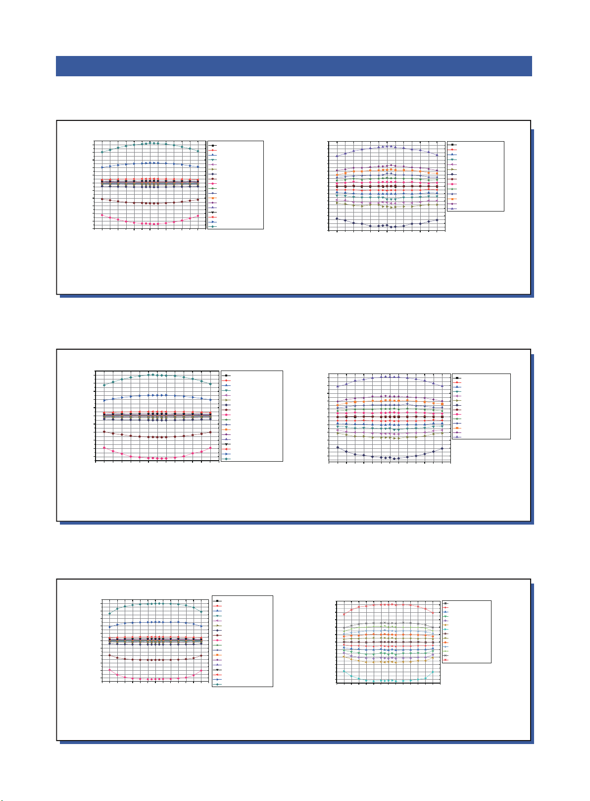
The horizontal test data of the sensor and the standard plate electrode are as follows:
Figure 11-1 the horizontal test data of standard plate electrode at a vertical distance of 500mm Figure 11-2 the horizontal test data of standard plate electrode at a vertical distance of 500mm
① Figure 11 shows the test data at different horizontal test distances under a vertical test distance of 500mm, the standard plate electrode of
600mm*600mm stainless steel electrode, and the sensor with the center position of the calibration plate as the coordinate origin:
② Figure 12 shows the test data at different horizontal test distances under a vertical test distance of 300mm, the standard plate electrode of
600mm*600mm stainless steel electrode, and the sensor with the center position of the calibration plate as the coordinate origin:
③ Figure 12 shows the test data at different horizontal test distances under a vertical test distance of 100mm, the standard plate electrode of
600mm*600mm stainless steel electrode, and the sensor with the center position of the calibration plate as the coordinate origin:
It can be seen from the above two horizontal test charts that the measurement error of the sensor can be kept within 5% within the horizontal
distance range of -200mm≤X≤200mm under the vertical test distance of 500mm for the 600*600mm calibration plate.
It can be seen from the above two horizontal test charts that the measurement error of the sensor can be kept within 5% within the horizontal
distance range of -200mm≤X≤200mm under the vertical test distance of 300mm for the 600*600mm calibration plate.
It can be seen from the above two horizontal test charts that the measurement error of the sensor can be kept within 5% within the horizontal
distance range of -200mm≤X≤200mm under the vertical test distance of 100mm for the 600*600mm calibration plate.
The test voltage value of the sensor(V)
Horizontal test distance(mm)
Calibration plate voltage+100V
Calibration plate voltage-300V
Calibration plate voltage-400V
Calibration plate voltage-500V
Calibration plate voltage+200V
Calibration plate voltage+300V
Calibration plate voltage+400V
Horizontal test distance(mm)Horizontal test distance(mm)
Figure 12-1 the horizontal test data of standard plate electrode at a vertical distance of 300mm Figure 12-2 the horizontal test data of standard plate electrode at a vertical distance of 300mm
Figure 13-1 the horizontal test data of standard plate electrode at a vertical distance of 100mm Figure 13-2 the horizontal test data of standard plate electrode at a vertical distance of 100mm
The test voltage value of the sensor(V)
8QGHUWKHFRQGLWLRQRIWKHYHUWLFDOWHVWGLVWDQFHRI3PP
WDNHWKHFHQWHUSRLQWRIWKHFDOLEUDWLRQSODWHDVWKHFRRUGLQDWH
RULJLQDQGPRYHWKHVHQVRUKRUL]RQWDOO\IRUWHVWLQJ
8QGHUWKHFRQGLWLRQRIYHUWLFDOWHVWGLVWDQFHRI3PP
WDNHWKHFHQWHUSRLQWRIWKHFDOLEUDWLRQSODWHDVWKHFRRUGLQDWH
RULJLQPRYHWKHVHQVRUKRUL]RQWDOO\IRUWHVWLQJ
8QGHUWKHFRQGLWLRQRIWKHYHUWLFDOWHVWGLVWDQFHRI1PP
WDNHWKHFHQWHUSRLQWRIWKHFDOLEUDWLRQSODWHDVWKHFRRUGLQDWH
RULJLQDQGPRYHWKHVHQVRUKRUL]RQWDOO\IRUWHVWLQJ
8QGHUWKHFRQGLWLRQRIYHUWLFDOWHVWGLVWDQFHRI1PP
WDNHWKHFHQWHUSRLQWRIWKHFDOLEUDWLRQSODWHDVWKHFRRUGLQDWH
RULJLQPRYHWKHVHQVRUKRUL]RQWDOO\IRUWHVWLQJ
Calibration plate voltage-0V
Calibration plate voltage-100V
Calibration plate voltage-200V
Calibration plate voltage-300V
Calibration plate voltage-400V
Calibration plate voltage-500V
Calibration plate voltage-1000V
Calibration plate voltage-5000V
Calibration plate voltage-10000V
Calibration plate voltage+0V
Calibration plate voltage+100V
Calibration plate voltage+200V
Calibration plate voltage+300V
Calibration plate voltage+400V
Calibration plate voltage+500V
Calibration plate voltage+1000V
Calibration plate voltage+5000V
Calibration plate voltage+10000V
Calibration plate voltage-0V
Calibration plate voltage-100V
Calibration plate voltage-200V
Calibration plate voltage-300V
Calibration plate voltage-400V
Calibration plate voltage-500V
Calibration plate voltage-1000V
Calibration plate voltage+0V
Calibration plate voltage+100V
Calibration plate voltage+200V
Calibration plate voltage+300V
Calibration plate voltage+400V
Calibration plate voltage+500V
Calibration plate voltage+1000V

Instructions
On-line mode
The plane of the electrostatic detection window of the sensor should be parallel to the surface of the object to be measured, and the detection
distance(the standard detection distance specified above: 5mm, 10mm, 25mm, 50mm, 100mm, 150mm, 200mm, 250mm, 300mm, 350mm, 400mm,
450mm, 500mm, 550mm, 600mm, 700mm) and detection gear should be selected according to the amount of static electricity carried by the charged
object and the use environment during using; the detection data displayed by the terminal is the most accurate at this point.
On-line mode: (Monitoring terminal, integrated power supply and communication software must be purchased separately. Please refer to the
instruction manual of system monitoring terminal and system integrated power supply for comprehensive on-line mode )
These three network ports of the 24V power adapter, the monitoring terminal, and the electrostatic sensor are both power ports and communication
ports which can be used in common.
Connection to monitoring terminal
Connection to PC
IMS Smart Controller
WAN/LANP4
P3P2P1 POWER
P1-P4 : 1/2-VCC 3-RS485_B 4-RS485_A 5/6-GND 7-C_V
TH
/HV
AL
8-C_ACT/Clean 9-PE(Metal shield)
Red-V
TH
/HV
AL
ACT/Clean-GreenACTWrok/Link
NEXT
SCAN
NEXT
LINK
SET
SCROLL
Connect to AC
power supply
Cable
Cable
Handheld terminal
Network adapter
Electrostatic sensor
SW1
Red-V
TH
/HV
AL
ACT/Clean-
Green
SW2 SW4SW3 SW5S W6 SW10SW8 SW9SW7 SW11 SW13SW12 SW14 SW15 SW16
P1
P17 P18
P2 P4
P20P19
P7 P8P6P5
P23 P24P22P21 P30 P32P27 P28P26
P9 P10 P12P11 P15 P16P14
V/A Display
IMS Power Supply
PC
Electrostatic sensor Electrostatic sensorElectrostatic sensor
communication converter
Integrated power supply
Cable
Cable
Operation and precautions...
to

Steps
Installation
①Use a Phillips screwdriver with a diameter of 3mm to turn the “DIST” circular DIP switch to select the test distance according to the amount of
static electricity carried by the charged object and the use environment.
②Toggle the "RANGE" circular DIP switch to select the detection gear according to the amount of static electricity carried by the charged object
and the use environment.
③Set the static electricity safety (alarm) threshold value through the remote control or monitoring software according to the withstand static voltage
value of the protected product.
Note: The threshold alarm indicator light is green when the detected static voltage value is within the set electrostatic threshold value while the
light is red when it exceeds the set threshold value.
④Use a Phillips screwdriver with a diameter of 3mm to turn the "ADDR" circular DIP switch to set the device address according to the production
station.
Set the sensor detection parameters according to the sensor label description:
Figure 16 Schematic diagram of sensor function
Figure 17 Schematic diagram of sensor installation orientation
Working environment
Working temperature:0℃→+ 50℃
Working humidity:30 → 65%RH

Precautions:
•Please read the operating instruction carefully before using the device in order to use it correctly.
•Please check the specifications of the power supply before powering on the product. Any power supply that does not meet the specifications may
cause damage or even failure to the product.
•Please operate at the specified ambient temperature (0 to 50°C).
•Keep a distance of more than 1m between the people and the product to avoid the impact of human static electricity on the test during the test.
Testers must wear electrostatic clothes, electrostatic caps and electrostatic shoes.
•The insertion depth of the φ5 diameter stainless steel mounting rod must not exceed the position of the detection switch on the back of the sensor.
•The surface of the φ5 diameter stainless steel mounting rod must not have insulating coating.
•Do not touch the electrostatic detection head during detection.
•Make sure that the sensor window is free from particulates and dust pollution.
•There should be no obstruction between the sensor and the detected object, otherwise the accuracy of the detection result will be affected.
•There should be no electrical equipment that affects the sensor within the detection distance of the sensor. Otherwise, the internal equipment and
chip may be failed or damaged.
•The plane of the sensor detection window should be parallel to the surface of the object to be measured to measure charged objects accurately.
•5 seconds of power connection before use. Otherwise, sometimes the data display will be unstable.
•The measured value is smaller than the actual electrostatic value of the charged object when the charged object is smaller than the calibration plate.
•The measured value is larger than the actual electrostatic value of the charged object when the charged object is larger than the calibration plate.
•Do not adjust zero in the state of static charge or during electrostatic measurement(non-electrostatic calibration process). The displayed static value
may be zero if zero is set during static testing.
•Do not install the sensor around high-voltage equipment, such as high-voltage power supplies, electrostatic generators, ion generators, and
eliminators. High voltages will affect the performance and detection accuracy of the sensor.
•Tighten the sensor when installing a high-vibration area; otherwise, data errors may occur.
•Please check the power cable or communication cable of the product regularly and replace it immediately if it is damaged. Otherwise it will easily
cause problems such as leakage of electricity, poor communication, and abnormal work.
•It may cause failure when the product suffers from mechanical shocks such as drops, bumps, etc..
•The whole equipment must be reliably grounded during use; Otherwise, it is easy to cause abnormal or even damage.
•Do not use the equipment in inflammable and explosive environment.
•Do not touch the electrostatic detection window with sharp objects.
•The product is strictly prohibited to touch liquid during use, otherwise there will be abnormal, resulting in electric shock or fire.
•Exceeding the detection range may result in product failure.
•Power must be turned off during inspecting or replacing the product, otherwise it may cause electric shock or fire.
•Do not disassemble the detector which is a precision equipment.
•It is strictly forbidden to disassemble products without authorization. Internal maintenance and repair must be carried out by professional personnel.
•The product is specially designed for detecting static electricity on the surface of objects and is strictly prohibited for other purposes. Any abnormal
use may machine failure, electric shock, fire and other hidden dangers.
•
Installation and use precautions
Sensor Accessories List
Part name Standard
or optional Part No. Specification Picture Application
Black shielded network
cable with crystal
connectors at both ends
(with bag)
Standard
8WXI00004 Super five double shielded
network cable
Used to connect product power
supply data interaction
Power Adapter Standard AP2930003
Input voltage: AC100-240V
Output voltage: DC24V
Output current: 2A
Output power: 48W
Used for product power supply
data interaction
National standard
power cord Standard 8YXG25110 Standard 1.8m,
Optional 3m/5m Used to connect adapters
Black shielded network
cable with single-ended
crystal head -2.5m (with
bag)
Optional 8WXI00002 Super five double shielded
single-ended network cable
Used to connect to PLC/machine/
large slitting machine, etc.
Mounting brackets Standard AP8038012 40*39*2 waist hole diameter
5mm, round hole diameter 3.5 Used to fix electrostatic sensors
Infrared remote control Standard AP2253002
AP&T Three-in-one panel
L*W*H=85.76*39.76*6.66 Used to adjust electrostatic sensors
BlowerBar
Sensor
CAL
SRZ
VTH+
VTH-
K-
K+
IB-
IB+
T+ T-
FR/SBR/S
FQ+
FQ-
IB+
IB-
FS+
FS-
RES
Warning:

NO Problems Reasons Solutions
1The power port indicator light
is off
Poor contact of the power cable Check whether the power cable is in good condition and securely connected
Wrong power cable connection Check the power cord is connected correctly
Power supply mismatch Confirm the power supply specification(INPUT:100—240VAC 50/60Hz;
OUTPUT:24VDC 2000mA)
2
The measured static voltage value
is abnormal or the error is too large
Poor contact of sensor grounding Confirm the sensor is well grounded
There are high voltage equipments, ionization
equipments or strong electromagnetic equipments
around the sensor
Remove high voltage equipments, ionizing equipments or strong
electromagnetic equipments
The range gear or detection distance is set
incorrectly Refer to the gear range setting table
Bearing set of sensor is improper Confirm the correct bearing set and refer to the precautions for operation and use
3The threshold alarm indicator
green light is off —— Return to factory for maintenance
4The threshold alarm indicator red
light is off
The set electrostatic threshold is larger or
exceeds the range
Refer to the gear range setting table to determine the static alarm threshold
reasonably according to the use environment and static control requirements,
5 Product has an odor Component burn out Return to factory for maintenance
6Please contact the manufacturer or seller if there are other unlisted problems or the problem cannot be solved through the above solutions.
Trouble shooting
1. Please store the equipment in a dry place away from light and do not put heavy pressure on it when not in use in order to ensure the good
performance of the product.
2. Do not vibrate the equipment strongly when using it which is a precision detector.
AP-YV3303 intelligent electrostatic sensor has undergone rigorous testing and aging treatment before ex-work. Its performance has
completely reached the relevant indicators marked in the usage instruction. AP&T makes a commitment to the customer that any defective
parts inspected by AP&T will be repaired or replaced free of charge within one year from the date of purchase. However, this commitment
does not apply to:
1、The device is incorrectly used.;
2、Damage caused by negligence or accident during use;
3、Modified, disassembled or repaired by other service departments not authorized by Anping Company;4、Faults are caused by external factors such as fire, earthquake, flood and abnormal voltage.
AP&T shall not be liable for any incorrect use of the products except for repair or replacement of parts as specified above.
After-sales service
Maintenance

专业创造价值
AP&T
Professional electrostatic intelligent monitoring/analysis
and elimination solution provider
Speciality Creates Value
AP&T
Shanghai Anping Static Technology Co.,Ltd
Tel : +86-21-64517676
Fax : +86-21-64517673
Postcode : 200233
Website : www.ap-static.com
Address : 3/F,Building 27,No.69,Guiqing Road,Shanghai,China
Table of contents
Other AP&T Accessories manuals
Popular Accessories manuals by other brands

Held
Held Helite user guide

Lightolier
Lightolier Lytespan 8676B specification

La Crosse Technology
La Crosse Technology TX-63U-IT instruction manual

Pepperl+Fuchs
Pepperl+Fuchs LUC-M10 Safety instructions

Allen-Bradley
Allen-Bradley Rockwell Automation VisiSight 42JT installation instructions

Chamberlain
Chamberlain SWG-0500 installation instructions