APART PM1122 User manual

PM1122
Instruction manual


Instruction manualPM1122
3
PM1122 Manual

4
Pre-amplifier

Instruction manualPM1122
5
Introduction
• After reading these pages, most of you will be able to connect
sources and operate this unique pre-amp/mixer without
further instructions. For more details, please take a look at the
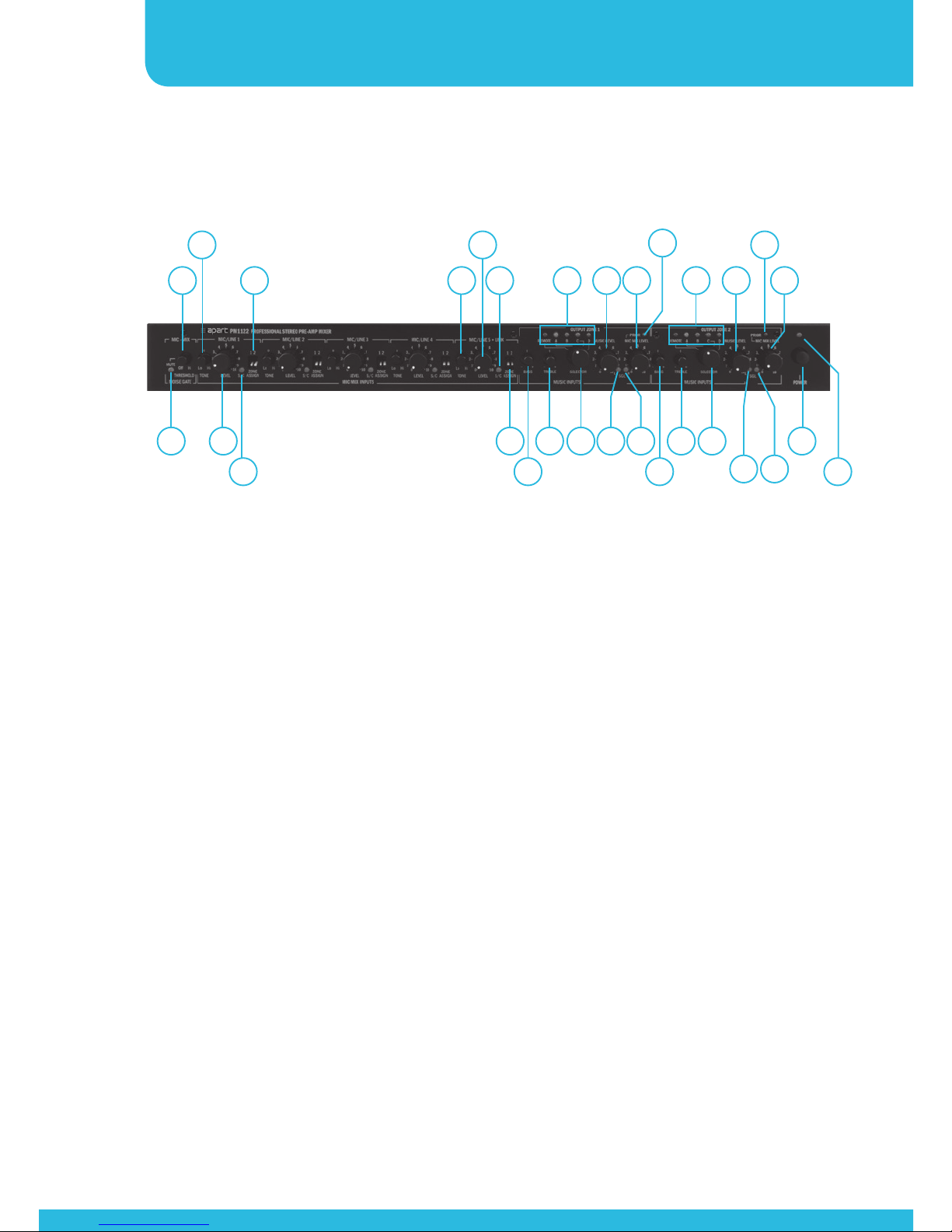
blockdiagram for better understanding and refer to the front
and rear panel layout descriptions on the next pages.
• The PM1122 features 5 mono mic/line balanced inputs with
individual sensitivity, level and tone adjustment potmeters. Each
mic input has its own phantom dipswitch at the back. Each mic
input can be assigned to zone 1 and/or zone 2 outputs with
dipswitches on the front of the preamp. Don’t use unbalanced
sources in combination with phantom power turned on on
the same channel ! Every mic/line channel has its own signal/
clip led, it lights green when a suffi ciently strong signal is
present, and turns red when the input is overloaded, turn down
the sensitivity adjustment at the rear to prevent unwanted
overloads !
• The 5 mic/line inputs (+ the adjustable chime) are all being
mixed together to the mix mic output after passing through
the adjustable noise gate. This circuit mutes the mic/line + the
chime output signal mix output when no suffi ciently strong
signal is present. The gate is active (closed) when the yellow led
lamp next to the gate sensitivity knob is lit. Use the gate only
to mute unwanted mic noise in your mic/line signal, it is not a
“vox” or “voice over”circuit. Set the threshold until the gate
“opens” when you are talking softly (not shouting !) into one
of the connected mics or when a mono line signal is present or
when the chime is activated (fi rst set the chime and mic levels
to an appropriate level). The combined output is separately
available at the rear of the device and allows you to use

6
Pre-amplifier
multiple PM1122 units in a chain with even more mics, output
zones or line sources.
• A separate mix/mic input is also provided to accept the mix/
mic signal from another PM1122 preamp’s mic mix output. The
level of this input can be adjusted with the mic/line 5 potmeter
at the front. You can also use this “line input from another
PM1122” as an unbalanced mono line input. When the
settings are all done correctly, you can use both inputs mic/line5
and link input simultaneously because they are being mixed
together internally.
• Mic inputs 1 and 2 offer an external switch connection on the
euroblock connector to activate the chime and priority. Chime
level is also presettable at the rear. Set its level to zero if you
don’t need the chime.The rear priority dipswitches allow you to
preset if line level mute per zone is activated yes or no in case
a priority mic contact is activated. Mono inputs are numbered
from 1 to 5 and are all mixed together, so in fact you can use
this single priority contact in parallel for all 5 inputs if required
(e.g. 5 call mics in a supermarket).
• PM1122 also has 4 stereo line level inputs called A to D. Line
level is presettable at the rear, this allows signals from various
sources to sound equally loud when you are switching from
one source to another. Line levels reaching from MP3 player’s
headphone outputs up to professional line levels from mixers or
other sound sources like tuners, CD players etc can be applied
to these unbalanced cinch connectors. Line inputs can be
assigned to two zones with the front music input selectors, or
can be remotely controlled with the separately available remote
control units.

Instruction manualPM1122
7
• Zone outputs are individually switchable to mono or stereo at
the back and have separate bass, treble, priority set and music
level adjustment per zone. Zone 1 and 2 outputs are available
unbalanced on cinch connectors and zone 1 also available
balanced on euroblock connectors.
• Finally there is the balanced emergency input with priority
contact and adjustable input level. Level is presettable at the
rear only for safety reasons.
• For remote control and local signal input, there are 2 pcs RJ45
style connectors available at the rear, one connector per zone.
These are NOT LAN compatible !!! Don’t connect any LAN
cable from computer or other networks to these terminals, they
are meant for connecting Apart-audio remote control systems
only. See the manual of these units for more details.

8
Pre-amplifier
Front panel
1. Power on / off switch. Push the button to turn power on and
off. As an experienced audio device user, you know you have
to switch on the preamp fi rst, and then the power amp. When
powering off, please turn off the power amps fi rst and then
the preamp.
2. Power led: this led lights when power is switched on.
3. Mute led: this led lights up when the mute circuitry or
noise gate is closed. Use it to eliminate unwanted noise or
background noise coming through from your mic/line inputs.
4. Noise gate threshold: set the knob to the off position if you
don’t want to use the noise gate. Set the gate so that it opens
(mute led dark) when you talk into one of the mics connected
to the mic/line 1 to 5 connectors. Please take notice that the
chime signal is also routed through this gate, so use it only as a
noise suppressor.
5. Tone control mic/line 1 to 4: turn the knob to darken the tone
(turn to the left) or to brighten the tone (turn to the right).
1
2
3
4
5
6
7
8 9 11 15 24 26 2917 20
21
12 14 23
27
25
28
16 18 19
13 22
10 30

Instruction manualPM1122
9
6. Mic/line 1 to 4 level: use this knob to adjust the mic 1 to 4 level.
7. S/C led: signal/clip led: the led lights up green when the mic
signal is suffi ciently strong, and becomes red if the mic preamp
is clipping. Turn the preset input trimmer of the corresponding
input down at the back of the unit when the led becomes red.
The red clip leds monitor the input circuit at all times, even
when the level on the front panel is turned to the zero position.
8. Zone assign dipswitches: activate the dipswitches to assign mic/
line input 1 to 4 to zone 1 and/or zone 2 output. Dipswitch
down = input assigned.
9. Tone control mic/line 5 + link: turn the knob to darken the tone
(turn to the left) or to brighten the tone (turn to the right).
10. Mic/line 5 + link level: use this knob to adjust the mic/line 5
level and/or the link input.
11. S/C led: signal/clip led: the led lights up green when the mic/
line signal is suffi ciently strong, and becomes red if the mic
preamp is clipping. Turn the preset input trimmer of the
corresponding input down at the back of the unit when the led
becomes red. The red clip leds monitor the input circuit at all
times, even when the level on the front panel is turned to the
zero position.
12. Zone assign dipswitches: activate the dipswitches to assign mic/
line input 5 or the link input to zone 1 and/or zone 2 output.
Dipswitch down = input assigned.
13. Zone 1 bass tone control: effective on music signals only.
14. Zone 1 treble tone control: effective on music signals only.

10
Pre-amplifier
15. Zone 1 line input indicator leds: these leds indicate which line
or music source input has been assigned to zone 1 output.
The red remote led indicates that the input selector shall be
operated by a separately available remote control unit only.
16. Zone 1 line/music input selector: turn this rotary input selector
to select input from line inputs A to D or set it to remote
control.
17. Music level knob: turn this volume knob to adjust the zone 1
music level.
18. Signal led: this green led indicates that a signal is present on
the left zone 1 output.
19. Signal led: this green led indicates that a signal is present on
the right zone 1 output.
20. Mic mix level knob: turn this volume knob to adjust the
microphone mix signal (mic/line 1-5 + link input) for zone 1.
21. Priority led: this led lights up when priority is activated by the
emergency input and/or by the mic 1 or mic 2 switch at the
rear and when priority is activated for zone 1 with the rear
dipswitch.
22. Zone 2 bass tone control: effective on music signals only.
23. Zone 2 treble tone control: effective on music signals only.
24. Zone 2 line input indicator leds: these leds indicate which line
or music source input has been assigned to zone 2 output.
The red remote led indicates that the input selector shall be
operated by a separately available remote control unit only.

Instruction manualPM1122
11
25. Zone 2 line/music input selector: turn this rotary input selector
to select input from line inputs A to D or set it to remote
control.
26. Music level knob: turn this volume knob to adjust the zone 2
music level.
27. Signal led: this green led indicates that a signal is present on
the left zone 2 output.
28. Signal led: this green led indicates that a signal is present on
the right zone 2 output.
29. Mic mix level knob: turn this volume knob to adjust the
microphone mix signal (mic/line 1-5 + link input) for zone 2.
30. Priority led: this led lights up when priority is activated by the
emergency input and/or by the mic 1 or mic 2 switch at the
rear and when priority is activated for zone 2 with the rear
dipswitch.

12
Pre-amplifier
Optional balanced mic transformers
The PM1122 printed circuit board has all the necessary provisions to
add optional microphone input transformers. This modifi cation can
only be done by a qualifi ed technician.
To access the transformer locations, remove the bottom and lid
from the preamp. On the componentside of the PCB you will fi nd
5 locations called IT1 to IT5. Furthermore, you will have to remove 2
capacitors per added transformer according to the list below.
We recommend the following brand and type of transformer:
Neutrik NTM-1.

Instruction manualPM1122
13
Back panel
MICROPHONE INPUT
NUMBER
PCB LOCATION CAPACITOR TO
REMOVE
MIC1 IT1 C13 & C14
MIC2 IT2 C213 & C215
MIC3 IT3 C44 & C45
MIC4 IT4 C57 & C58
MIC5 IT5 C85 & C86
The suggested transformer’s pin layout fits perfectly on the PCB
After soldering the transformer from the soldering side, please
remove the 2 capacitors as listed in the table to complete the modifi
cation.
1 2 3 4
5
6
7
8 9 10
11 12
13 15
14 16 17
18 19 20

14
Pre-amplifier
1. 24 VDC connector: connect the supplied power supply on these
connectors. Please mind the polarity (+ and - ) if you have to
reconnect the connector to the power cord.
2. Open collector outputs zone 1 and 2: These outputs can sink
max 50mA at 24 VDC max. See the schematic below for
connection details. Don’t apply any AC or mains voltages to
these connectors. Always use a separate power supply if you
want to power external relays etc.
3. Zone 1 and 2 remote control connectors: connect the
separately available Apart-Audio remote controllers on these
RJ45 style connectors. These are not LAN or other kind of
network compatible connectors !
4. Zone 1 / 2 priority assign dipswitches: set the zone 1 and/or
zone 2 dipswitch(es) to “Y”if you want priority mics to mute
the line/music signal on zone 1 and/or zone 2 output.
5. Zone 1 / 2 mono stereo switch: set this switch to”mono” to
mix the zone 1 and/or zone 2 stereo signal(s) to a monophonic
signal.
6. Zone 2 output: connect your zone 2 amplifi er system on these
unbalanced cinch line outputs.
7. Zone 1 output: connect your zone 1 amplifi er system on these
unbalanced cinch line outputs.
8. Zone 1 output: connect your zone 1 amplifi er system on these
balanced euroblock line outputs.
9. Emergency input: connect your balanced emergency signal with
emergency switch on these euroblock connectors. The input
is transformer balanced (e.g. for connecting a telephone line
signal).

Instruction manualPM1122
15
10. Emergency level: adjust emergency level with this knob. Please
note that when the emergency switch is activated, the music
or mic/line mix signals will be muted and only the emergency
signal will be heard in zone 1 and 2. The emergency switch
does not activate the chime.
11. Chime level: use this knob to preset the chime level when mic1
or mic2 priority is activated. Please note that the chime signal
is also sent through the noise gate. If you set the noise gate
threshold at a high level, chime signal may be muted by the
noise gate. Set the noise gate threshold at a lower level instead
of boosting the chime level. The noise gate has been added to
mute unwanted mic noise and it is not a “vox” circuit !
12. Line A to D stereo line level inputs: these unbalanced cinch
connectors accept stereo line level signals coming from music
sources such as tuners or CD players, or even headphone outs
from portable music players, up to line levels coming from
professional mixing desks. Max input level is +14dBv !
13. Line A to D sensitivity preset: turn these knobs to preset the line
A to D levels so that they sound equally loud when switching
from one to another.
14. Mic mix output: this unbalanced cinch connector contains the
mic mix signal from mic/line inputs 1 to 5 and is meant to be
connected to another PM1122 in a chain.
15. Link input: this unbalanced cinch connector accepts the signal
from another PM1122 in a chain. You could also use it as a
mono unbalanced line 5 input. The level from this input is
adjusted with the front mic/line 5 + link knob.

16
Pre-amplifier
16. Mic 1 to 5 phantom switch: fl ip down the dipswitch from
channel 1 to 5 if you want to apply a 20 VDC phantom power
to input 1 to 5. Don’t use unbalanced sources in combination
with phantom power turned on on the same channel !
17. Mic/line 1 to 5 sensitivity knobs: turn these knobs to adjust mic/
line 1 to 5 input sensitivity and gain: the signal/clip led present
on mic/line input 1 to 5 is your guide: turn down the knob to
the left fi rst, and gradually turn it to the right while you are
speaking loudly in the mic or while the line signal is applied.
When the signal/clip led turns red, you are overloading the
input. Turn the knob to the left a little until the led doesn’t light
up red anymore. Take your time to preset all mic/line inputs this
way.
18. Input 3 to 5 input blocks: connect your balanced mic or line
signals on these euroblock connectors.
19. Input 1 and 2 input blocks: connect your balanced mic or line
signals on these euroblock connectors. Additionally connect
the mic 1 and/or mic 2 switch(es) on these blocks to activate
the chime and priority. These contacts can be used for inputs
3-5 as well. Please note the priority system; the MIC1 contact
will mute MIC2-3-4-5 + Music, and the MIC2 contact will mute
Music (if dipswitch 4 is set).
20. Ground connector: connect your system’s ground or safety
ground on this connector if this is not already done by
mounting the unit in a properly grounded rack.
For additional functionality, there are also 2 open collector outputs at the rear controlled
by the priority switch, one output per zone. They can only be used by qualifi ed
technicians. Maximum sinkable current per output is 50 mA, maximum voltage is 24VDC.
No AC voltages are allowed on these outputs ! In case of inductive loads such as relays,
provide additional measures to avoid damage to the open collector outputs.

Instruction manualPM1122
17
Please use the schematic shown below as a guideline:

18
Pre-amplifier
Blockdiagram

Instruction manualPM1122
19

20
Pre-amplifier
Technical Specifications
Outputs
Output stereo zone 1 balanced Euroblock connector 6 dB, 2 V,
100 ohm
Output stereo zone 1 unbalanced Cinch connector 0dB, 1 V, 100 ohm
Output stereo zone 2 unbalanced Cinch connector 0dB, 1 V, 100 ohm
Frequency response 20Hz - 22 kHz
Noise > 93 dB
THD < 0,008 %
Crosstalk > 70 dB
Max nominal gain +6 dB
Max output voltage +19 dBV, 9 V
Insert pcb for signal-processing Pcb ready, processors optional
Tone control zone 1 and 2 Bass 75 Hz +/-10 dB treble 10 kHz
+/-10 dB
Music and micmix level control 0-10 V VCA operated
Chime level 2-Tone, > 1 V
Priority outputs Open collector zone 1 and 2, max
24 V, max 50 mA
Line inputs
Line a to d Cinch connectors l & r channel
Line a to d sensitivity Trim from 330 mV/ -10 dBV to 5,3
V / +15 dBV
Line a yo d impedance 17 kΩ
Line a to d max input level +20 dBV
Other manuals for PM1122
1
Table of contents
Other APART Music Equipment manuals