Apeks 2000 PSI Series User manual

2000PSI
5LD, 20LD, 5LDX5LD, AND 20LDX20LD
BOTANICAL OIL EXTRACTION SYSTEM
OWNER’S MANUAL
WARNING
FAILURE TO FOLLOW THE SETUP AND OPERATION PROCEDURE
PROVIDED IN WITHIN THIS MANUAL MAY VOID THE EXTRACTION
SYSTEM’S WARRANTY
Apeks LLC
150 Commerce Blvd.
Johnstown OH 43031
844-446-4262
www.apekssupercritical.com
Scan this QR code to get the most
recent version of this manual!

Updated 6/16/2016 Copyright Apeks LLC, 2014
2
Table of Contents
1. Unpacking Instructions ......................................................................................................................4
1.1. Shipping Crate Inspection...............................................................................................4
1.2. Unpacking Apeks Extraction System..............................................................................5
1.3. Unpacking Diaphragm Compressor................................................................................7
2. System Requirements.......................................................................................................................9
2.1. Facility.............................................................................................................................9
2.2. Electrical.........................................................................................................................9
3. Setup and Assembly........................................................................................................................11
3.1. Leveling Feet ................................................................................................................ 11
3.2. Coolant Connections..................................................................................................... 11
3.3. CO2Connections.......................................................................................................... 13
3.4. Air System Connections................................................................................................ 14
3.5. Electrical Connections between the Apeks system and diaphragm compressor ..........16
3.6. Chiller/Heater Setup......................................................................................................17
3.7. Diaphragm Compressor Setup ..................................................................................... 18
3.8. Software Updates and Email Alerts .............................................................................. 19
4. System Operation............................................................................................................................21
4. 2000-5LD, 20LD, 5LDx5LD, and 20LDx20LD Overview............................................... 21
4.1.1 Automation Systems Overview..................................................................................... 22
4.1.5.Pre-Cleaning................................................................................................................. 23
4.1.7 Depressurize System after Recovery............................................................................ 23
4.1.12 Removing Oil from Separator #1................................................................................. 23
4.1.32 Closing Separation vessels......................................................................................... 26
4.1.34 After Every Run Maintenance...................................................................................... 26
4.1.41 Opening Extraction Vessel........................................................................................ 289
4.1.47 Removing Spent Material from Extraction Vessel ....................................................... 30
4.1.48 Loading Botanical or Other Media............................................................................... 30
4.1.51 Closing Extraction Vessel............................................................................................ 30
4.1.55 Chiller Start Up..........................................................................................................311
4.1.59 Evacuating the System (Removing air from the system prior to extraction) .............. 311
4.1.64 Conducting an Extraction .......................................................................................... 322
4.1.74 Recommended Operating Parameters........................................................................ 34
5. Troubleshooting...............................................................................................................................35
5.1. Ice On Separator .......................................................................................................... 35
5.2. Low Extractor Pressure................................................................................................. 35
5.3. Extractor Overpressure –Orifice Clog, or Orifice is to small......................................... 35
5.4. Low Separator Pressure –Orifice Clog, or Orifice is to small....................................... 36
5.5. Wrong Orifice Size........................................................................................................ 36
5.6. High Separator #1 Pressure (>380-psi) and Low Separator #2 Pressure..................... 36
5.7. Oil carryover from Separator 1 to Separator 2 or Pump................................................ 37
6. Maintenance....................................................................................................................................38
Appendix A. Screenshots ………………………………………………………………………………………...42
Appendix B. 2000-5LD, 20LD, 5LDx5LD, and 20LDx20LD Piping and Instrumentation Diagram............47
Appendix C. CO2Phase Diagram.........................................................................................................500
Appendix D. Training Process ..............................................................................................................522
References...........................................................................................................................................566
Updated 6/16/2016 Copyright Apeks LLC, 2014
3
Critical Safety Overview
Throughout these instructions, this symbol is used to indicate that the instructions are
critically important to your safety and the safety of your system. Failure to follow the
instructions as written can result in a rapid release of high pressure CO2potentially
causing equipment or personnel damage.
WARNING
Subcritical and Supercritical CO2systems operate under high pressure. Operators must be fully trained
and familiar with the system. Failure to operate the system can result in equipment damage and/or
bodily injury.
WARNING
Subcritical and Supercritical CO2systems use large amounts of CO2during operation. Ensure that
system is installed in a well-ventilated area to prevent buildup of CO2 which can cause asphyxiation.
Use of a CO2monitor is strongly recommended.
WARNING
Opening a vessel under pressure can result in a rapid release of pressure and ejection of the material
inside the vessel. DO NOT ATTEMPT TO OPEN A VESSEL UNDER PRESSURE! Always make sure
a vent path for the vessel is opened and the corresponding pressure gage reads zero prior to loosening
the vessel hammer unions.
WARNING
Subcritical and Supercritical CO2systems are designed to operate indoors. Extreme temperatures
(below 65°F and above 80°F) will negatively impact the functionality of the system. The environmental
temperature range is for the system, chiller, pump and CO2bottles.
WARNING
Only use Propylene Glycol and distilled water in the chiller and cooling system. Never use Deionized
Water in the chiller or cooling system.

Updated 6/16/2016 Copyright Apeks LLC, 2014
4
1. Unpacking Instructions
Apeks 2000-5LD, 20LD, 5LDx5LD, and 20LDx20LD systems are shipped in three separate crates.
One containing the chiller, one containing the diaphragm compressor and one containing the
botanical extraction system. Following are the steps for removing the system from the crates and
making service connections for initial use.
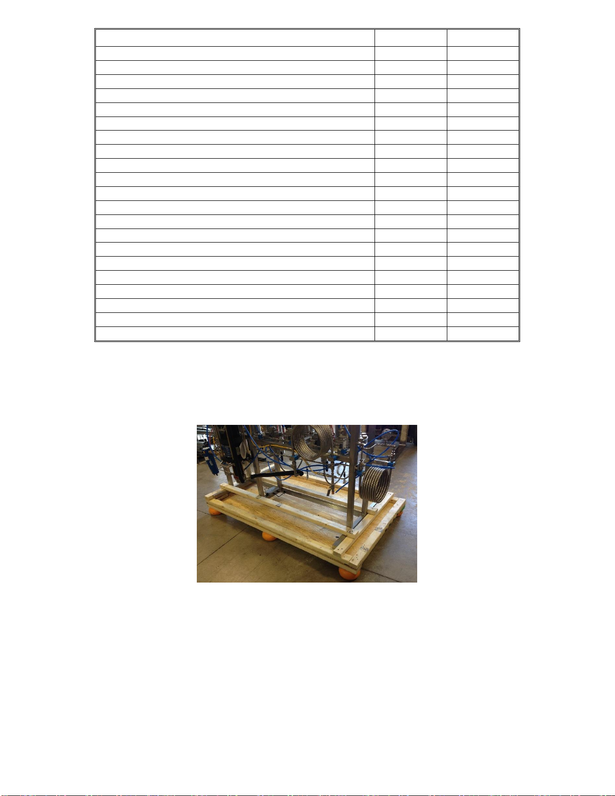
Shipping Crate Inspection
1.1.1. Prior to accepting the crate(s), ensure that the crating material is similar to the pictures
shown below. Also, please verify that that there is no external damage to the wood
crate(s). If damage is found, do not accept the delivery from the shipping company. IF
ACCEPTNG MINOR DAMAGED CRATE(S), WRITE ON ALL SHIPPING
DOCUMENTS MINOR DAMAGE FOUND ON CRATE(S). Additionally, call Apeks at
740-809-1160 to report damage and take pictures of each damaged location.
Diaphragm Compressor Crate Extractor Crate Chiller Crate
1.1.2. Locate the two TiltWatch Plus sensors on the outside of the crates. Ensure that the
crates have not exceeded 30° in any direction. If the crates have exceeded 30°, do not
accept the delivery from the shipping company and contact Apeks at 740-809-1160
immediately.
Figure 1. Tiltwatch sensor

Updated 6/16/2016 Copyright Apeks LLC, 2014
5
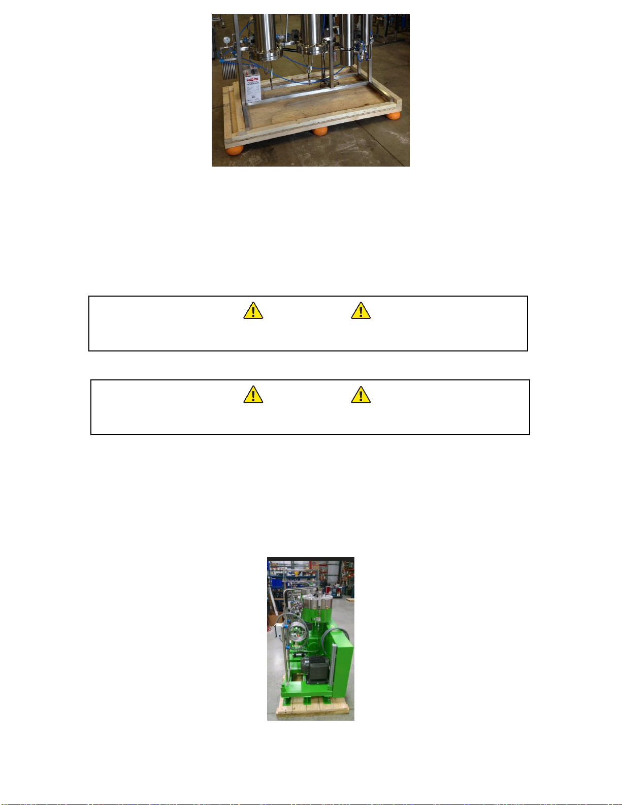
Unpacking Apeks Extraction System
1.1.3. Remove the plywood from the all four sides and the top of the crate using a Phillips
head screwdriver.
Figure 2. Appearance of crate with top and sides removed
1.1.4. Remove the support hardware from inside the crate. Ensure that all the material in the
table below is present.
Figure 3. Overview image of support hardware
Updated 6/16/2016 Copyright Apeks LLC, 2014
6
1.1.5. Please make sure you have the following list of support hardware.
Description
Order Qty.
Ship Qty.
Extraction System
1
4 Qt Metal Funnel
1
Food Grade Thread Lube/Anti-Seize
1
3-in and 4-in Plunger w/36-in long handle
1
Orifices
1
Leveling feet with rubber pads
4
Hard Buna-n O-Rings
2
3-in Silicone Gaskets
2
4-in Silicone Gaskets
2
CO2 Cylinder Gasket
2
CO2 Cylinder double hose assembly
1
Indicator Light
1
Polyscience Chiller
1
Versilube
1
Vacuum Pump w/vacuum hose assembly
1
Write-on squeeze bottle
1
3/8” Compression Plug
1
Air Compressor
1
4 Ft. 5/16-In O.D. Air Hose
1
5/16 x 1/4 MNPT fitting for Air Compressor
1
Connecting hoses
2
1.1.6. Remove the horizontal 2x3s from the top of the crate using a hammer or crowbar.
1.1.7. Remove the vertical 2x4s from the four corners of the crate using a hammer or crowbar.
1.1.8. Remove the two 2x3s running across the top of the system frame and the two 2x3s
running alongside the system frame using a Phillips head screwdriver.
Figure 4. Image of 2x3s support top and sides of system frame.
Updated 6/16/2016 Copyright Apeks LLC, 2014
7
Figure 5. Appearance of crate with 2x3s removed.
1.1.1. Using a forklift or pallet jack lift the system off the base of the crate. It may be
necessary to tip the system slightly towards the back in order to slide the forks under
the stainless steel horizontal frame support members.
1.1.1.1. The system weighs in excess of 700 lbs, take extreme caution when lifting or
moving the system. Do not attempt this step without adequate help.
WARNING
The system weighs over 700-lbs (318-kg), use a minimum of three people
to stabilize the system while moving.
1.1.2. Remove the chiller from the second crate.
WARNING
The chiller weighs over 150-lbs, use a minimum of two people or a lift cart
when moving the chiller assembly.
1.1.3. KEEP the crate and all packing materials for future shipping should the system ever
need to be moved to another facility or shipped back to Apeks.
Unpacking Diaphragm Compressor
1.1.4. Remove the plywood from the all four sides and the top of the crate using a Phillip’s
head screwdriver, and a crow bar.
Figure 6. Appearance of crate with top and sides removed

Updated 6/16/2016 Copyright Apeks LLC, 2014
8
1.1.5. The diaphragm compressor is designed to be anchored to the floor in order to keep it
from moving during operation. A forklift is required to lift and remove the diaphragm
compressor off of the pallet and place on the floor. Not removing the diaphragm from
the pallet will void the warranty.
1.1.5.1. The system weighs in excess of 1500-lbs, take extreme caution when lifting or
moving the system. Do not attempt this step without adequate help.
WARNING
The compressor weighs over 1500-lbs (680-kg), use a minimum of three
people to stabilize the system while moving.
2.3.2.2 Before lowering the diaphragm compressor to the floor, install the rubber feet
provided, to the frame. These rubber feet can then be anchored to the floor.
2.3.4 The orientation of the diaphragm compressor should be directly behind the Apeks
system with the stainless steel belt cover facing away from the Apeks system as shown below.
Figure 7. Orientation of the diaphragm compressor and Apeks system.

Updated 6/16/2016 Copyright Apeks LLC, 2014
9
2. System Requirements
Facility
2.1.1. Temperature –Apeks systems are designed to run in a climate controlled facility,
where the temperature is maintained between 65°F and 80°F.
2.1.2. Dust Control –Apeks systems should not be placed in an environment that has
excess dust from other manufacturing operations.
2.1.3. Location –Apeks systems are designed to be installed on a level concrete or
similar stable surface.
Electrical
2.1.4. Please refer to the two tables below in order to determine the right electrical
specifications for your system.
Table 1. General Electrical Specs.
Table 2. Diaphragm Pump Electrical Specs.
Pump Unit
Complete
Goes with Voltage Phase Full Load Amps Recommended connection
1L systems 115VAC 1 16 20A 115VAC wall receptacle. NO GFI
Diaphragm Systems
Chiller size Goes with Voltage Phase Full Load Amps from Polyscience manual Polyscience recommended
connection
1/4HP 1L systems 115VAC 1 12.5 NEMA 5-15R wall receptacle. NO GFI
3/4HP
5000PSI automated
systems, diaphragm
systems with small (7.5-
10HP) compressor
230VAC 1 12.2 NEMA 6-15R receptacle
1.5HP
Large (12.5HP) diaphragm
compressor systems (eff
10/15/2015)
230VAC 1 31.4
Field wired- Polyscience recommends
40Amp dedicated hard wired circuit
Control Panel Goes with Voltage Phase Main Fuse or breaker size Apeks recommended connection
1L 115VAC 1 10A
NEMA 5-15R wall receptacle with surge
protector
All other systems 115VAC 1 10A
NEMA 5-15R wall receptacle with surge
protector
Air Compressor Goes with Voltage Phase FLA Recommended connection
Porter Cable 3gal All diaphragm systems 115VAC 1 10 NEMA 5-15R wall receptacle NO GFI
IR 15HP 5L 5000 psi systems 230VAC 3 37.6A Field wired- IR recommends 65A fuse
IR25HP 20L 5000 psi systems 230VAC 3 66.5A Field wired- IR recommends 100A fuse
See Diaphragm Table
Compressor
Motor HP
Phase Voltage Motor FLA Recommended Fuses where field wired Compressor mfg and model
15 1208V 66A AJT125 PPI4100
15 1230V 58A AJT100 PPI4100
15 3208V 46A AJT80 PPI4100/PDC4
15 3230V 42A AJT70 PPI4100/PDC4
15 3460V 21A AJT40 PPI4100/PDC4
12.5 1 208V 52A AJT90 PDC4
12.5 1 230V 48A AJT90 PDC4
10 1230V 38A AJT70 PPI2072
10 3208V 32A AJT60 PPI2072
10 3230V 28A AJT50 PPI2072
10 3460V 14A AJT25 PPI2072
7.5 1 230V 40A AJT70 PDC3
7.5 3 208V 24A AJT50 PDC3
7.5 3 230V 22A AJT40 PDC3
7.5 3 460V 11A AJT20 PDC3
Updated 6/16/2016 Copyright Apeks LLC, 2014
10
2.1.4.1. Note that the diaphragm compressors can be ordered in several voltages and
phase at time of purchase.
2.1.4.2. A 480V three phase diaphragm compressor would require a different electrical
service. Contact Apeks at 740-809-1160 ext. 703 to discuss this before installing
electrical service if you choose the 480V option.
2.1.4.3. Refer to section 4.5 for electrical connections between the Apeks system and the
diaphragm compressor.
2.1.4.4. Note different size chillers are dependent of diaphragm pump size.
WARNING
Do not modify the power connections.

Updated 6/16/2016 Copyright Apeks LLC, 2014
11
3. Setup and Assembly
The Apeks 2000-5L, 20L, 5Lx5L and 20Lx20L systems, chiller and diaphragm compressor come
assembled and require only facility hookup and system interconnect installation.
Leveling Feet
3.1.1. Use a fork lift or pallet jack to raise the system approximately 6-in off the ground, use
clamps or tie down straps to secure the system to the forks/jack to prevent it from
tipping.
3.1.2. Insert the supplied leveling feet into the four threaded holes on the bottom of the
extraction system. Ensure that the leveling feet are not threaded into the scale
receiver too far or they will hit the frame and negate scale functionality.
Figure 8. Extraction system leveling feet.
Coolant Connections
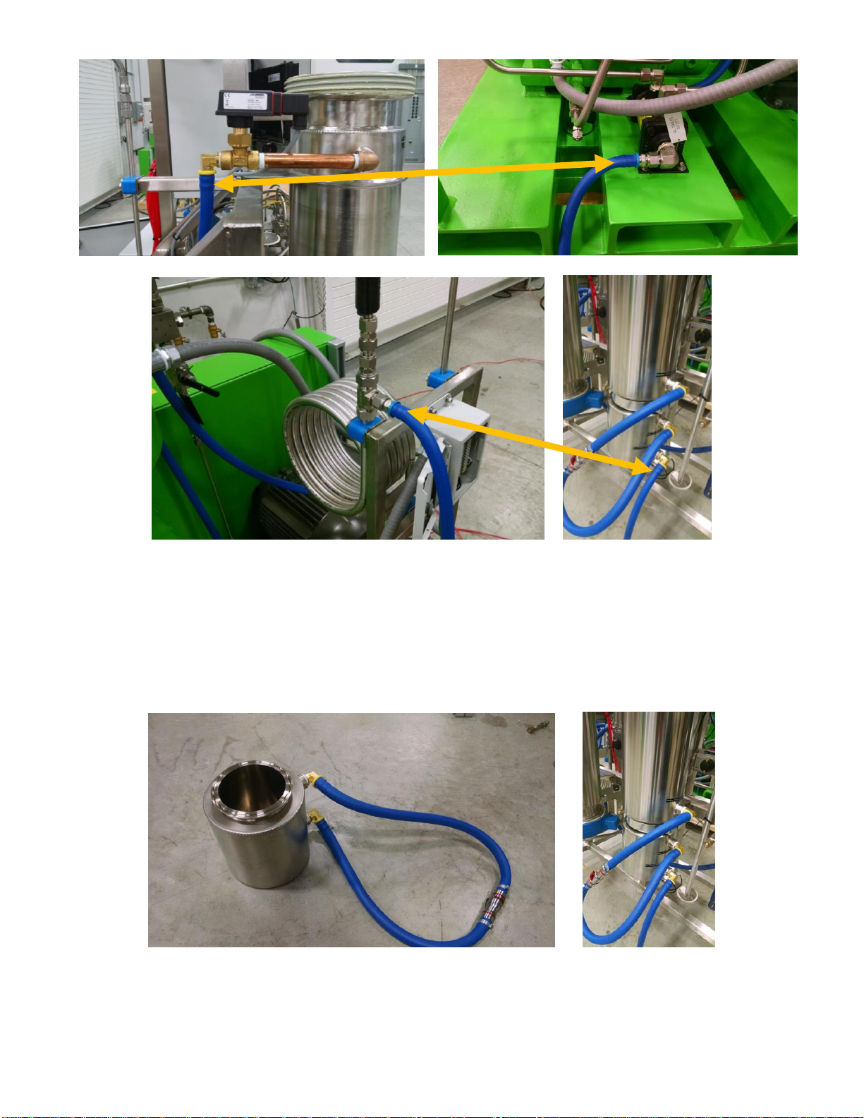
3.1.1. Connect the blue cooling line from the outlet of the chiller to the temperature control
coiled heat exchanger on the far left side of the Apeks system as shown below. Please
note that these lines should not lay on any sharp edges where abrasion can occur.
3.1.2. Connect the blue cooling line from the inlet of the chiller to the top of Separator 2 on the
Apeks system as shown below.
Figure 9. Location and orientation of coolant lines from the chiller to the Apeks system.
3.1.3. Connect the blue cooling line from the top of Extractor (Extractor A on the double
systems) to the oil heat exchanger on the base of diaphragm pump as shown below.
3.1.4. Connect the blue cooling line from the regenerative coiled heat exchanger on the
diaphragm pump to the bottom of the collection cup as shown below.
Updated 6/16/2016 Copyright Apeks LLC, 2014
12
Figure 10. Location and orientation of coolant lines from the Apeks system to the diaphragm compressor.
3.1.5. The separator side of the extraction system will be pre-assembled. In the event that
adjustments need to be made or the system gets taken apart during use, the water
flow path should always be from bottom to top in any vertically oriented vessel.
Figure 11. Image of 4 inch separator coolant lines. Please note that these lines should not lay on any sharp
edges where abrasion can occur.

Updated 6/16/2016 Copyright Apeks LLC, 2014
13
3.1.1. The temperature probe(s) for the extractor are pre-assembled into the bottom of the
extraction vessel(s).
3.1.1.1. If operating a dual extraction system be sure to move the probe output wire to the
vessel being used (if using both vessels either probe can be used)
Figure 12. Location of temperature probe on bottom of extraction vessel.
CO2Connections
WARNING
CO2cylinders are under high pressure. Use proper storage and handling
procedures to prevent damage and sudden release of CO2from the
cylinder
3.1.2. CO2used with Apeks systems should be 99% purity or better (Medical, Food or
Instrument grade typically suffice), gas feed (not liquid feed), 50-lb, 75-lb or 100-lb
high pressure cylinders.
3.1.3. The two supplied hoses should be connected directly to the CO2cylinder valves. No
regulator is required. A supplied CGA-320 plastic gasket is required to seal the
connection between the hose and the CO2cylinder.
Figure 13. 50lb CO2cylinder(s) connections
Temperature
Probe
Updated 6/16/2016 Copyright Apeks LLC, 2014
14
3.1.4. The CO2line is typically preassembled on the 2000-5LD, 20LD, 5LDx5LD, and
20LDx20LD systems. If the line was not connected or was removed for
cleaning/shipping, reconnect the line to the tube fitting located on top of Valve 12.
The connection is a metal-to-metal seal and does not require any thread sealant.
Tighten 1/8 turn past finger tight or until leak free. Additional instructions regarding
these tube fittings is available at
http://www.swagelok.com/downloads/webcatalogs/EN/MS-13-151.pdf.
Figure 14. Double Bottle CO2Hose Connection
Air System Connections
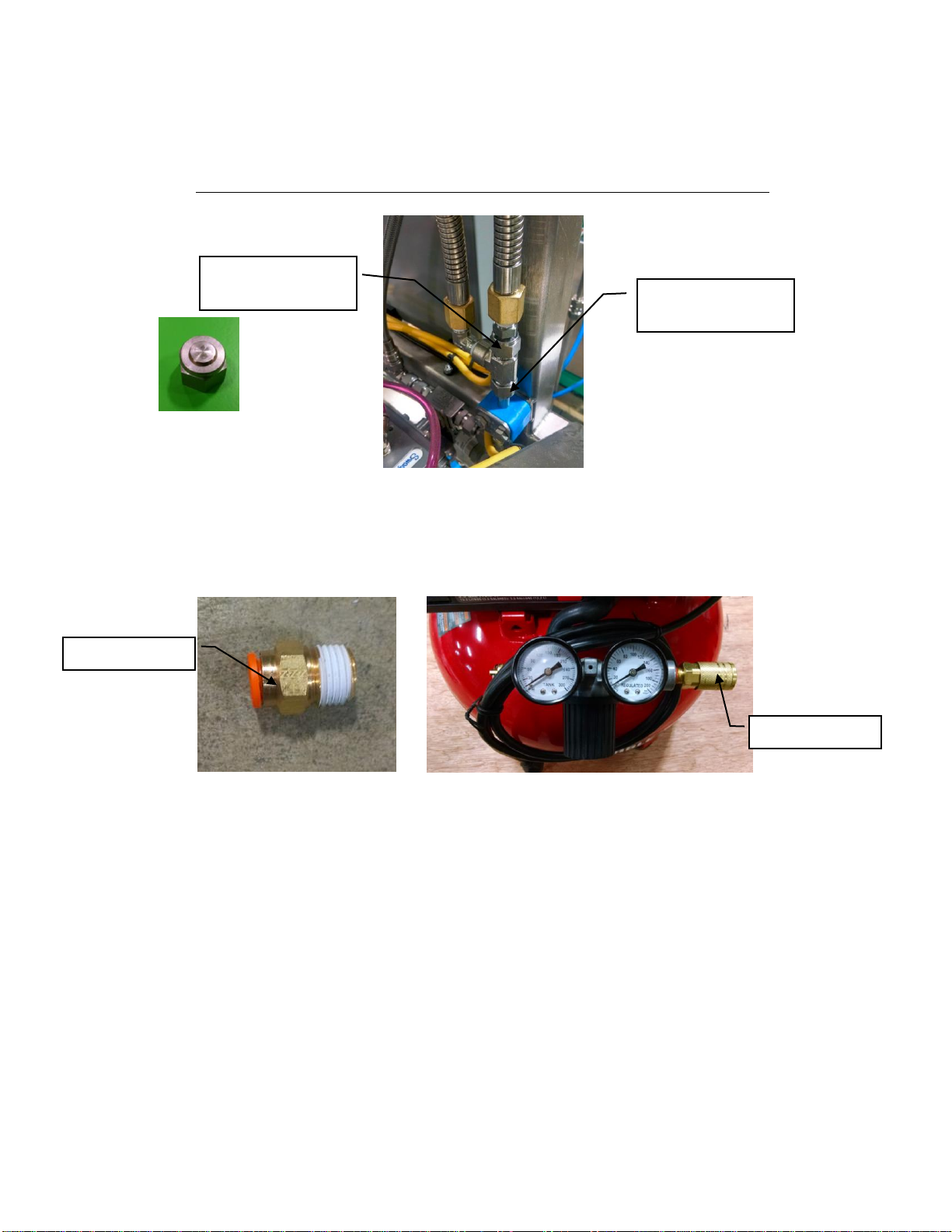
3.1.5. Replace the quick release fitting on the front of the air compressor with the 5/16
push to connect provided.
Figure 15. Switching fittings on the front of the mini air compressor.
CO2Cylinder Hose
Connection
Air Fitting
Remove
Plug location for
single bottle use

Updated 6/16/2016 Copyright Apeks LLC, 2014
15
3.1.6. Connect the 5/16 pink air hose from the air compressor to the push to connect fitting
on the back of the Apeks 2000 5LD, 20LD, 5LDx5LD, or 20LDx20LD system as
shown below.
Figure 16. Connecting the air compressor to the back of the Apeks system.

Updated 6/16/2016 Copyright Apeks LLC, 2014
16
Electrical Connections between the Apeks system and diaphragm compressor
3.1.7. Connect the diaphragm compressor electrical connections to the back of the Apeks
system as shown below by inserting labeled wire T1 to the bottom T1 of the motor
starter, T3 to T3, and ground wire to the ground terminal on the din rail immediately
to the left of the motor starter. NOTE: 3 Phase motors are wired differently.
Figure 17. Electrical connections from Diaphragm compressor to the Apeks system
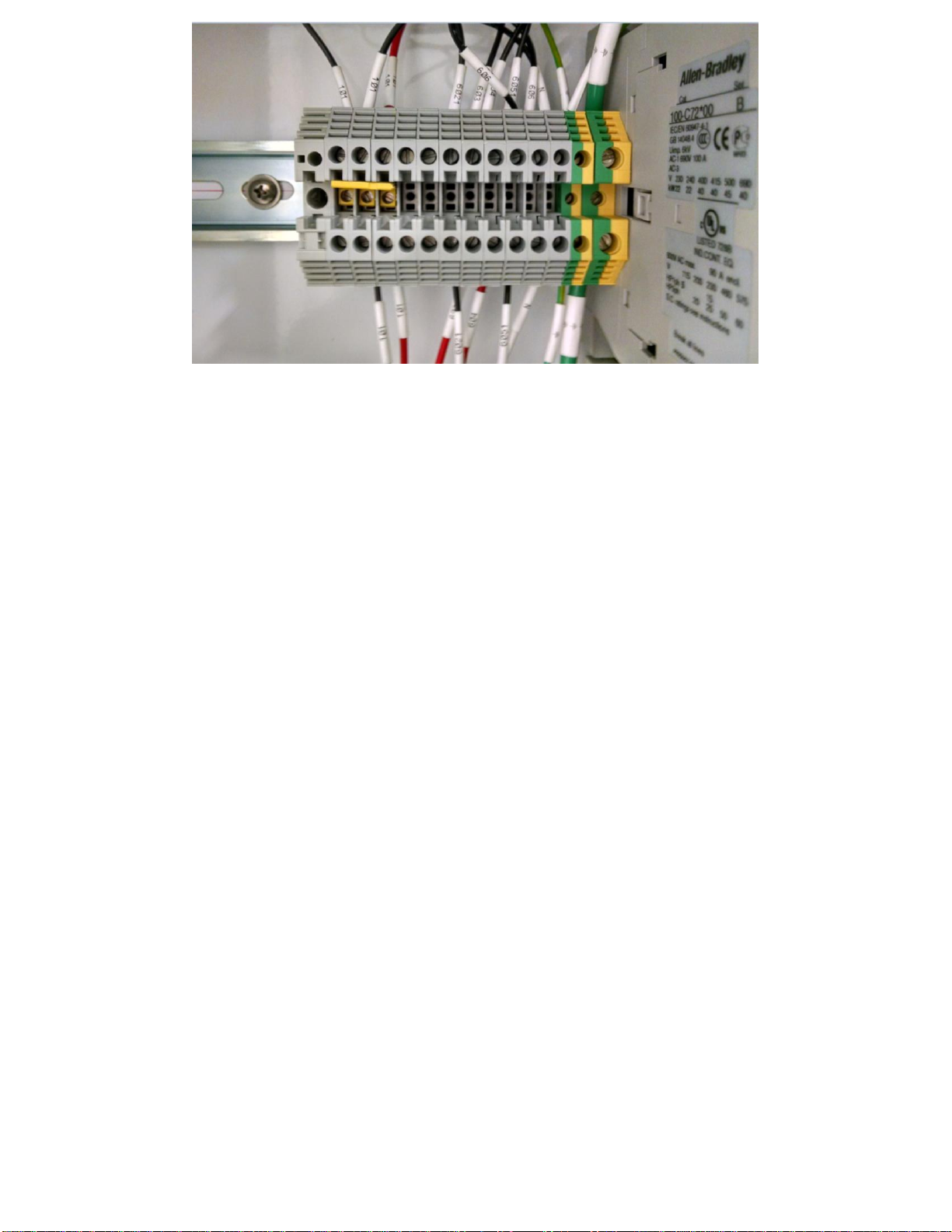
3.1.8. Wires for the pressure switches on the pump need to be wired in this panel as well.
3.1.8.1. Insert the conduit coming from the junction box on the pump into the receptacle
in the middle of the pump.
3.1.8.2. Terminate the wires in the bundle that are labeled into the terminal block
opposite of the wires with the same number. See figure below
Updated 6/16/2016 Copyright Apeks LLC, 2014
17
Figure 21. Pressure switch wiring from Diaphragm compressor to the Apeks system
3.1.9. Plug the extraction system control panel into a 110-V, 15-A, standard outlet.
3.1.10. Have a local electrician field wire the diaphragm pump and 1.5 HP Polyscience
chiller with the appropriate connections.
3.1.11. Have a local electrician field wire the diaphragm pump and ¾-HP Polyscience
chiller with the appropriate connections.
3.1.12. Do NOT plug anything into a GFI outlet.
Chiller/Heater Setup
3.1.13. Wire the chiller per the specs listed for the appropriate model in the electrical
section.
3.1.14. Plug the chiller into a 220-V, 15-A, NEMA 6-15R receptacle for ¾ HP Chillers
3.1.15. Coolant fluid (50/50 mix of distilled water and propylene glycol DO NOT USE
DEIONIZED WATER) is added to the system through the reservoir cap on the top of
the chiller.
3.1.15.1. On the initial fill the chiller will pump contents of the reservoir into the system
which will require additional fluid to be added until the system (water jackets and
hose) are full.
3.1.15.2. After the system is operational, recheck the coolant level (while the system is
running) and add more coolant as necessary.
3.1.16. Adjusting your system between Fahrenheit and Celsius doing the following:
3.1.16.1. Turn the circuit breaker on the back of the system to the off position.
3.1.16.2. Press and hold the menu button on the front of the chiller (button on the left).
3.1.16.3. Turn the circuit breaker back on. The display should show “dF” or “dC”
depending which was previously selected.
3.1.17. More detailed operating instructions for the heater/chiller can be found in the
manufacturer’s operating instructions.

Updated 6/16/2016 Copyright Apeks LLC, 2014
18
Diaphragm Compressor Setup
3.1.18. Connect the CO2 flexible hoses between the Apeks system and the diaphragm
compressor. Please note that these lines should not lay on any sharp edges where
abrasion can occur.
3.1.18.1. The inlet tubing on the pump (uninsulated) connects to the tube coming from out
under the control panel on extraction system.
3.1.18.2. The outlet tubing on the pump (insulated) is connected between the regenerative
heat exchanger attached to the pump and the tube coming down off valve 17A.
Figure 18. Stainless steel tubing connections from the diaphragm compressor to the Apeks system.
Figure 19. CO2 flexible hoses from the diaphragm compressor to the Apeks system. Please note that these lines
should not lay on any sharp edges where abrasion can occur.
3.1.19. Connect flexible tubing coming from pressure gauge on top of the pump head to the
pressure switch on the bottom of the pump electrical panel.
17a OUTLET
17b INLET
INLET
OUTLET
Updated 6/16/2016 Copyright Apeks LLC, 2014
19
Software Updates and Email Alerts
The Apeks 2000-5L, 20L, 5Lx5L and 20Lx20L systems should be connected to the internet via an
Ethernet cable. Connecting the Apeks system to the internet allows for software updates, and email
alerts.
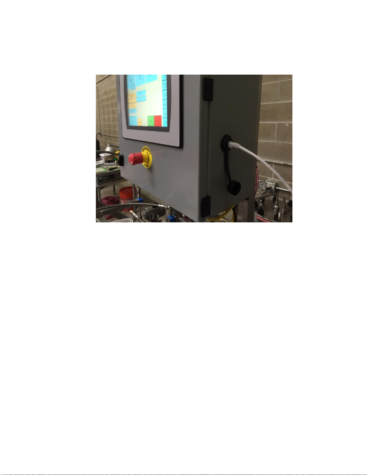
3.1.20. Attach an Ethernet cable to the Ethernet connection located on the side of the
electrical control box.
Figure 20. Ethernet cable plugged into the side of the control panel.
3.1.21. For email alerts, setup a designated email to be used only for the Apeks system.
The Apeks system will then send messages to a designated email, and then this email
will send messages to any person’s phone numbers you decide to forward messages
to.
3.1.22. After connecting your system to the internet via an Ethernet cable, and after
you’ve setup your designated email for the system, please contact our Software &
Electrical Support at 740-809-1160 ext. 703 or Technical Support ext. 1 for software
updates and setting up your email alerts (initial setup fees may apply).
3.1.23. After setting up your system for email alerts, you will then decide what messages
you would like to be notified of.
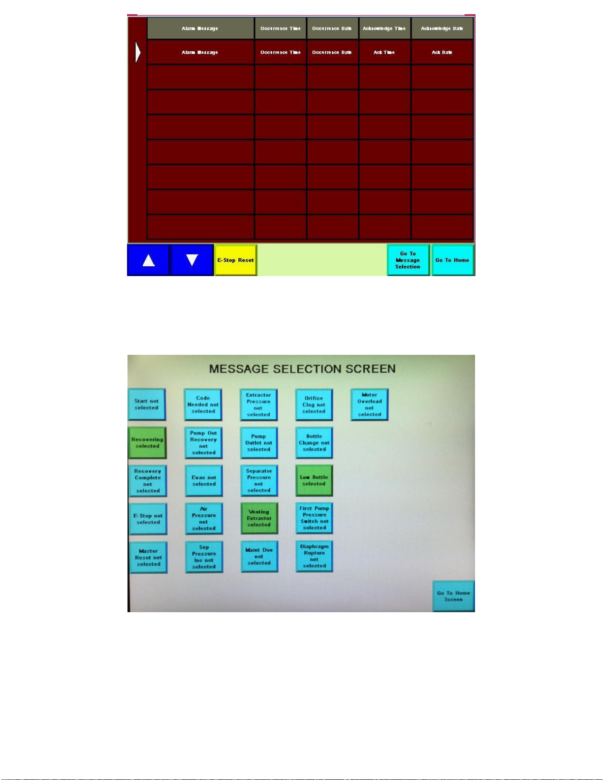
3.1.23.1. Click on the “Go to Message Selection” button located on the bottom of the alarm
screen.
Updated 6/16/2016 Copyright Apeks LLC, 2014
20
Figure 21. “Go to Message Selection” button located on the bottom of the alarm screen.
3.1.23.2. Now chose which messages you would like to have sent to your email on the
message section screen.
Figure 22. Message selection screen used to determine which messages you would like to have sent to your
email.
This manual suits for next models
4
Table of contents
Other Apeks Scrubber manuals


