Electrolux Professional Compass Pro W5600X User manual

Installation manual
Washer extractor
W5600X
Compass Pro
Type EXSM.X.
Original instructions
438 9057-10/EN
2021.09.21


Contents
Contents
1 Safety Precautions ..............................................................................................................................5
1.1 General safety information..........................................................................................................6
1.2 Commercial use only..................................................................................................................6
1.3 Symbols....................................................................................................................................6
2 Warranty terms and exclusions.............................................................................................................7
3 Technical data.....................................................................................................................................8
3.1 Drawing ....................................................................................................................................8
3.2 Technical data ...........................................................................................................................9
3.3 Connections ..............................................................................................................................9
4 Setup ...............................................................................................................................................10
4.1 Unpacking...............................................................................................................................10
4.2 Siting ......................................................................................................................................10
4.3 Mechanical installation ............................................................................................................. 11
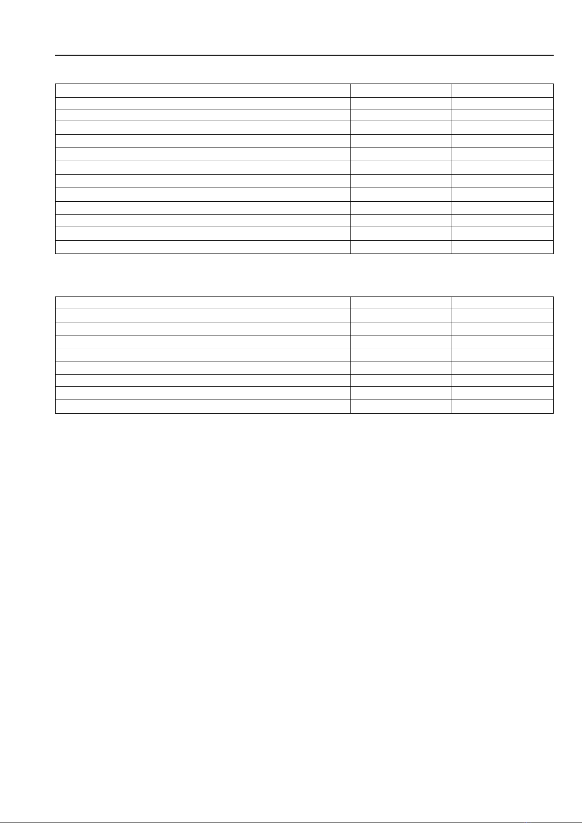
4.3.1 Foundation .................................................................................................................... 11
4.3.2 Casting a foundation.......................................................................................................12
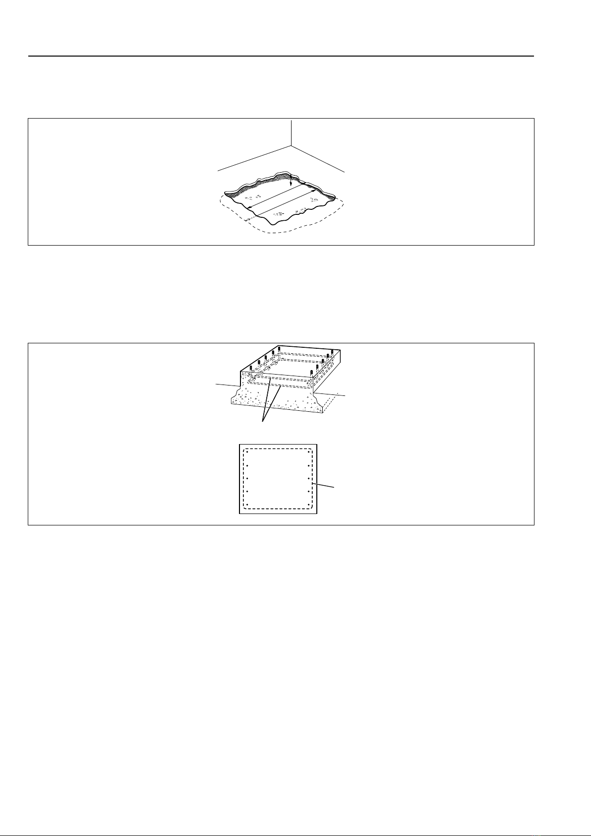
4.3.3 Chemical bolts ...............................................................................................................13
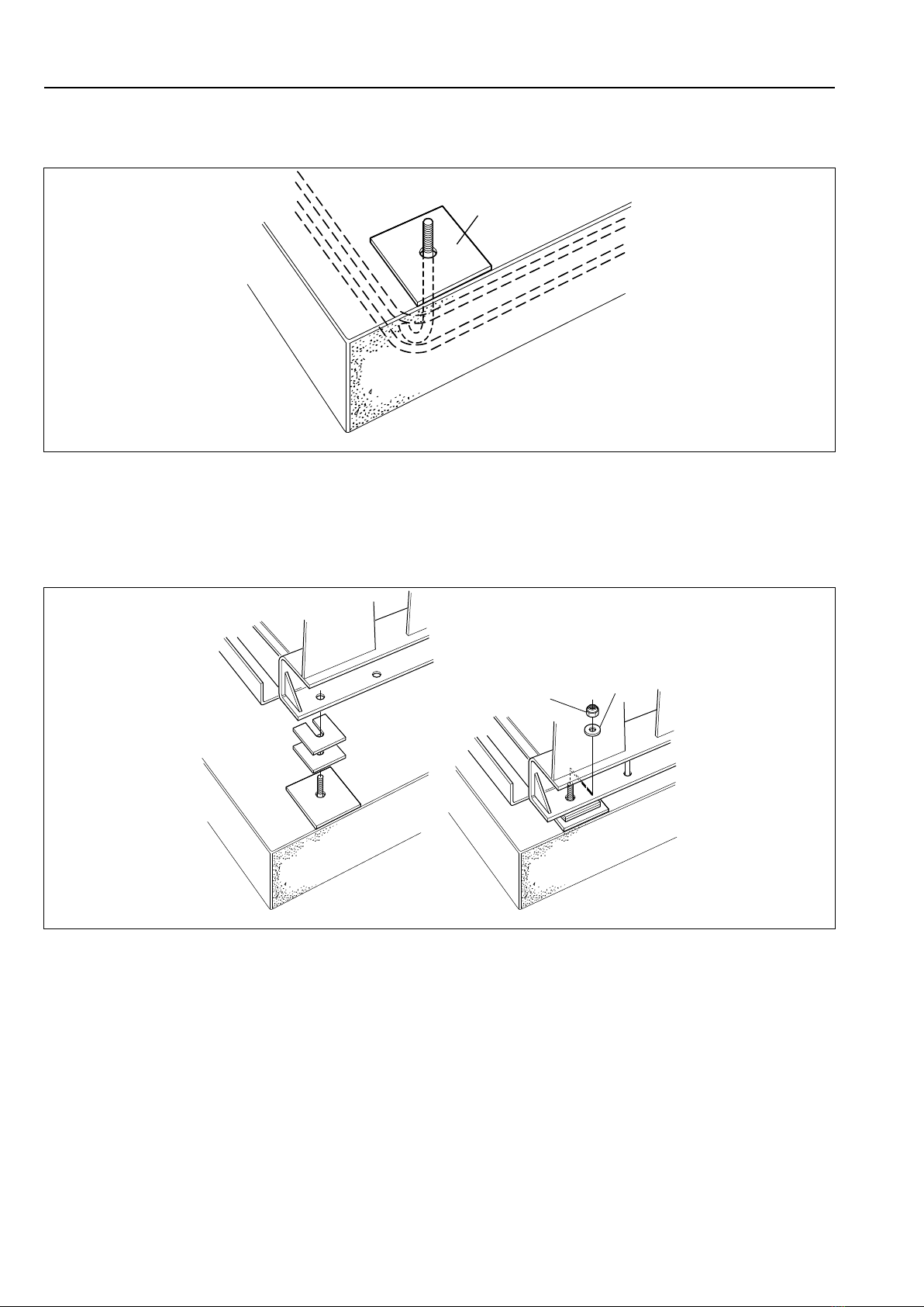
4.3.4 Fastening the machine....................................................................................................14
5 Water connection ..............................................................................................................................15
6 Connection of external dosing systems ...............................................................................................16
6.1 Connection of the hoses...........................................................................................................16
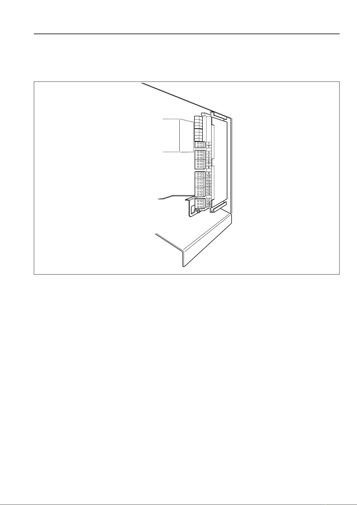
6.2 Electrical connection of external dosing system..........................................................................16
6.2.1 Machine without connectors............................................................................................17
6.2.2 Outputs .........................................................................................................................18
6.2.3 Inputs ............................................................................................................................19
7 Drain connection ...............................................................................................................................20
8 Detergent supply injector ...................................................................................................................20
9 Electrical connection..........................................................................................................................21
9.1 Electrical installation ................................................................................................................21
9.2 Electrical connections ..............................................................................................................21
9.3 Machine connection .................................................................................................................22
9.3.1 Three-phase connection .................................................................................................22
9.4 Functions for I/O-cards.............................................................................................................23
9.4.1 External coin meter/Central payment (2A) ........................................................................23
9.4.2 Central payment (2B)......................................................................................................24
9.4.3 Outputs for detergent signals and inputs for pause signals, "empty" signal and price re-
duction (2D) ...................................................................................................................25
9.4.4 Machines with I/O module type 3 .....................................................................................26
10 Steam connection .............................................................................................................................27
11 At first power up ................................................................................................................................28
11.1 Select language.......................................................................................................................28
11.2 Set time and date.....................................................................................................................28
12 Function check..................................................................................................................................29
13 Disposal information..........................................................................................................................30
13.1 Disposal of appliance at end of life ............................................................................................30
13.2 Disposal of packing..................................................................................................................30
The manufacturer reserves the right to make changes to design and component specifications.


Installation manual 5
1 Safety Precautions
• Servicing shall be carried out only by authorized personnel.
• Only authorized spare parts, accessories and consumables shall be used.
• Only use detergent intended for water-wash of textiles. Never use dry cleaning agents.
• The machine shall be connected with new water hoses. Re-used water hoses must not
be used.
• The machine's door lock must under no circumstances be bypassed.
• If the machine develops a fault, this must be reported to the person in charge as soon
as possible. This is important both for your safety and that of others.
• DO NOT MODIFY THIS APPLIANCE.
• When performing service or replacing parts, the power must be disconnected.
• When the power is disconnected, the operator must see that the machine is discon-
nected (that the plug is removed and remains removed) from any point to which he has
access. If this is not possible, due to the construction or installation of the machine, a
disconnection with a locking system in the isolated position shall be provided.
• In accordance with the wiring rules: mount a multi-pole switch prior to the machine to
facilitate installation and service operations.
• If different rated voltages or different rated frequencies (separated by a /) are stated at
the machine data plate, instructions for adjusting the appliance for operation at the re-
quired rated voltage or rated frequency are stated in the installation manual.
• The openings in the base, shall not be obstructed by a carpet.
• Maximum mass of dry cloth: 63.5 kg.
• A-weighted emission sound pressure level at working stations:
– Wash: 70 dB(A).
– Extraction: <70 dB(A).
• Maximum inlet water pressure: 800 kPa / 116 psi
• Minimum inlet water pressure: 50 kPa / 8 psi
• Additional requirements for the following countries; AT, BE, BG, HR, CY, CZ, DK, EE,
FI, FR, DE, GR, HU, IS, IE, IT, LV, LT, LU, MT, NL, NO, PL, PT, RO, SK, SI, ES, SE, CH,
TR, UK:
– The appliance can be used in public areas.
– This appliance can be used by children aged from 8 years and above and persons
with reduced physical, sensory or mental capabilities or lack of experience and knowl-
edge if they have been given supervision or instruction concerning use of the appliance
in a safe way and understand the hazards involved. Children shall not play with the ap-
pliance. Cleaning and user maintenance shall not be made by children without
supervision.
• Additional requirements for other countries:
– This appliance is not intended for use by persons (including children) with reduced
physical, sensory or mental capabilities, or lack of experience and knowledge, unless
they have been given supervision or instruction concerning use of the appliance by a
person responsible for their safety. Children should be supervised to ensure that they
do not play with the appliance.
– This appliance is intended to be used in household and similar applications such as:
(IEC 60335-2-7) staff kitchen areas in shops, offices and other working environments,

6Installation manual
farm houses, by clients in hotels, motels and other residential type environments, bed
and breakfast type environments, areas for communal use in blocks of flats or in
launderettes.
1.1 General safety information
The machine is only intended for water-wash use.
Do not hose down the machine with water.
In order to prevent damage to the electronics (and other parts) that may occur as the result of condensation, the ma-
chine should be placed in room temperature for 24 hours before being used for the first time.
1.2 Commercial use only
The machine/machines covered by this manual is/are made for commercial and industrial use only.
1.3 Symbols
Caution
Caution, high voltage
Read the instructions before using the machine

Installation manual 7
2 Warranty terms and exclusions
If the purchase of this product includes warranty coverage, warranty is provided in line with local regulations and sub-
ject to the product being installed and used for the purposes as designed, and as described within the appropriate
equipment documentation.
Warranty will be applicable where the customer has used only genuine spare parts and has performed maintenance
in accordance with Electrolux Professional user and maintenance documentation made available in paper or elec-
tronic format.
Electrolux Professional strongly recommends using Electrolux Professional approved cleaning, rinse and descaling
agents to obtain optimal results and maintain product efficiency over time.
The Electrolux Professional warranty does not cover:
• service trips cost to deliver and pick up the product;
• installation;
• training on how to use/operate;
• replacement (and/or supply) of wear and tear parts unless resulting from defects in materials or workmanship re-
ported within one (1) week from the failure;
• correction of external wiring;
• correction of unauthorized repairs as well as any damages, failures and inefficiencies caused by and/or resulting
from;
– insufficient and/or abnormal capacity of the electrical systems (current/voltage/frequency, including spikes and/
or outages);
– inadequate or interrupted water supply, steam, air, gas (including impurities and/or other that does not comply
with the technical requirements for each appliance);
– plumbing parts, components or consumable cleaning products that are not approved by the manufacturer;
– customer’s negligence, misuse, abuse and/or non-compliance with the use and care instructions detailed within
the appropriate equipment documentation;
– improper or poor: installation, repair, maintenance (including tampering, modifications and repairs carried out
by third parties not authorized third parties) and modification of safety systems;
– Use of non-original components (e.g.: consumables, wear and tear, or spare parts);
– environment conditions provoking thermal (e.g. overheating/freezing) or chemical (e.g. corrosion/oxidation)
stress;
– foreign objects placed in- or connected to- the product;
– accidents or force majeure;
– transportation and handling, including scratches, dents, chips, and/or other damage to the finish of the product,
unless such damage results from defects in materials or workmanship and is reported within one (1) week of deliv-
ery unless otherwise agreed;
• product with original serial numbers that have been removed, altered or cannot be readily determined;
• replacement of light bulbs, filters or any consumable parts;
• any accessories and software not approved or specified by Electrolux Professional.
Warranty does not include scheduled maintenance activities (including the parts required for it) or the supply of
cleaning agents unless specifically covered within any local agreement, subject to local terms and conditions.
Check on Electrolux Professional website the list of authorized customer care.

8Installation manual
3 Technical data
3.1 Drawing
D
3
C
1
2
B(a)
B(b)
E
FG
H
I
J
K
L
N
M
OR
Q
P
6
9
8
7
5
4
10
A
fig.8036
1 Operating panel
2 Door opening, ⌀535 mm
3 Detergent container
4 Cold water
5 Hot water
6 Drain valve
7 Liquid detergent supply, 6 x ⌀10 mm, 1 x ⌀16 mm and 1 x ⌀20 mm
8 Electrical connection
9 Steam connection
10 Detergent supply injector, powder, right or left side (option)
A B(a) B(b) C D E F
mm 1173 1951 1193 1673 33 93 600
G H I J K L
mm 540 1370 125 255 227 87
M N O P Q R
mm 85 802 103 1544 1361 587

Installation manual 9
3.2 Technical data
Weight, net kg 775
Drum volume litres 600
Drum diameter mm 980
Drum speed during wash rpm 38
Drum speed during extraction rpm 630
G-factor, max. 220
Heating: Electricity kW 35
Heating: Steam x
Heating: Hot water x
Frequency of the dynamic force Hz 10.5
Floor load at max extraction kN 10±15.6
Sound power/pressure level at extraction* dB(A) 83/66
Sound power/pressure level at wash* dB(A) 69/52
* Sound power levels measured according to ISO 60704.
3.3 Connections
Water valves DN 25
Recommended water pressure kPa 200–600
Continuous operating pressure kPa 50–800
Capacity at 300 kPa l/min 110
Drain valve ⌀outer mm 75
Draining capacity l/min 170
Steam valve connection DN 20
Recommended steam pressure kPa 300–600
Functioning limits for steam valve kPa 50–800

10 Installation manual
4 Setup
4.1 Unpacking
Note!
Two persons are recommended for the unpacking.
The machine is delivered bolted onto the transport pallet and packed in a crate or box.
Remove packing from the machine.
Remove the bolts between the machine and pallet. There are two bolts in the front of the machine and two bolts in
the back of the machine.
fig.7675
Remove the machine from the pallet.
Note!
When moving the machine, handle it with care.
Place the machine on its final position.
4.2 Siting
Install the machine close to a floor drain or open drain.
The machine should be positioned so that there is plenty of room for working, both for the user and service personnel.
The figure shows minimum distance to a wall and/or other machines.
400 mm /
15 3/4 inch
50 mm /
1 15/16 inch
50 mm /
1 15/16 inch
fig.W00176F

Installation manual 11
4.3 Mechanical installation
Floor
The machine is designed to be bolted in position to a concrete floor or specially prepared concrete foundation.
The machine must be securely fastened to a suitable foundation using M16 (5/8 inch) threaded rod, flat washers and
lock nuts or lock washers. Failure to properly secure the machine to its foundation, or securing the machine to an in-
adequate foundation, will result in severe vibration, damage to the machine, and will void the manufacturer's
warranty.
For installation on an existing concrete floor, the floor must be at least 200 mm thick and of good quality. If the floor
does not meet these requirements, then a 150–200 mm high concrete foundation should be made.
4.3.1 Foundation
Measurements for foundation:
A
BD
E
F
G
I
H
K
O
N
M
L
C
FRONT
P
fig.5896
Measurement mm
A 1138
B 998
C 70
D 66
E 100
F 327
G 327
H 100
I 185
K 1003
L 1086
M 1251
N 1314
O 1441
P 22 (diameter)

12 Installation manual
4.3.2 Casting a foundation
• Break up the existing floor to a depth of approx. 75 mm and check that the sides of the hole are tapered outward
so that the longest side at the bottom measures 130 mm more than at the top.
a
a+ 130 mm / 5 inches
fig.7663
• Moisten the hole well and apply cement to the sides and bottom.
• Pour the concrete into the prepared base mould and make sure that the surface is level. Bolts are to extend 38
mm above the concrete.
Rebars (A) shall be used around the base. The rebars shall be placed between the bolts and the edge of the
foundation.
• The concrete should be left to set for at least two days before mounting the machine on the plinth.
A
A

Installation manual 13
4.3.3 Chemical bolts
An alternative to breaking up the existing floor or foundation is to use chemical bolts M16.
1. Mark and drill four holes (⌀18 mm) 125 mm deep for the chemical bolts.
Check the previous table for the correct position of the holes.
2. Clean the drilled holes.
3. Put down the chemical ampule in the hole.
4. Rotate the bolt into the hole, so that the glass ampule is broken and its contents mixed.
5. Rotate the bolt to correct depth.
Note!
Do not rotate the bolt against the concrete bottom. Check that the chemicals have filled the hole
completely.
6. Remove the drilling machine with the mounting tool. Hold the bolt with one hand. Let the bolt harden before the
machine is mounted.
1 2 3 4 56
fig.5917A
Time for hardening, due to different concrete temperatures:
– 10°C: 6 hours
– 5°C: 2.5 hours
± 0°C: 1 hour
5°C: 30 minutes
10°C: 20 minutes
15°C: 15 minutes
20°C: 10 minutes

14 Installation manual
4.3.4 Fastening the machine
Place wide steel shims (A) on the concrete foundation over the bolts.
A
fig.7666
Position the machine on the foundation.
Check that the machine is in level and stand firmly on all supporting points. Spacing washers must be mounted if one
or more of these points is not resting against the foundation.
Place flat washers (B) over the foundation bolts and secure the machine in position by tightening the self-locking nuts
(C).
B
C
fig.7667A

Installation manual 15
Tighten the nuts. Check and tighten the nuts every week for the first month.
15
12
10 73
48
11
962
fig.5902
It is of the upmost importance that the machine is placed in level, from side to side as well as front to rear. If the
machine is not properly levelled, it may result in “out-of-balance” without a true unbalance in the drum.
5 Water connection
All water intake connections to the machine should be fitted with manual shut-off valves and filters, to facilitate instal-
lation and servicing. In certain cases non-return valves will need to be fitted before the machine to comply with local
plumbing regulations.
Water pipes and hoses should be flushed clean before installation.
The machine shall be connected with new water hoses. Re-used water hoses must not be used.
Hoses are to be of an approved type and grade and comply with IEC 61770.
After installation hoses must hang in gentle arcs.
All connectors present on the machine must be connected. The table shows the possible connection options, which
will depend on the water types to be connected to the machine. Information is also available on the panel above the
connections.
Water type Water connection
1
2
3
4
• Cold and hot 1. Cold (DN 25)
2. Hot (DN 25)
3. Cold or hot for detergent supply (DN 20) (Not
used)
4. Cold or hot for detergent supply (DN 20)
Water pressure:
Miniumum: 40 kPa (0.4 kp/cm2)
Maximum: 1 MPa (10 kp/cm2)
Recommended: 200–600 kPa (2–6 kp/cm2)
Note!
If the water pressure is below the minimum value, the wash result can not be guaranteed for certain program.

16 Installation manual
FOR AUSTRALIA:
The appliance shall be installed in accordance with AS / NZS 3500.1
The appliance need to be installed using dual check valves.
6 Connection of external dosing systems
6.1 Connection of the hoses
The machine is prepared for connection of external dosing systems or water re-use systems etc.
The connections are closed at delivery. Open any of the connections that shall be used by drilling a hole where the
hose shall be connected.
Note!
Make sure there is no burrs left after drilling. When removing burrs make sure burrs does not fall into the si-
phon breaker.
A = ⌀10 mm, drill = ⌀5 mm (used for external dosing systems).
Use the enclosed template by putting it over the connection and drill in the hole.
B = ⌀16 mm, drill = ⌀11 mm (used for external dosing systems).
C = ⌀20 mm, drill = ⌀15 mm (used for external dosing systems).
1
2
3
B
C
A
fig.W00413
Always connect hoses on connections A with a hose clamp.
For connections B and C; if the hoses are made of a soft material such as silikon or similair, use a cable tie to fasten
the hose on the connection. If the hoses are made of a hard material, it is not recommended to make the connection
tighter by using a cable tie.
Note!
Equipment for external dosing must only be connected to work on pump pressure and not on network
pressure.
6.2 Electrical connection of external dosing system
The power supply to the external dosing system must never be connected to the machine’s incoming terminal
block or to the edge connectors on the I/O-board.

Installation manual 17
6.2.1 Machine without connectors
Connect the external dosing system to the I/O board, which is located to the right of the incoming power supply.
The I/O board has edge connectors for connecting external dosing systems.
Edge connectors on the I/O board can be loosened for connecting cables.
fig.6572
11 = N
18 = Program run
12 = Signal 1
13 = Signal 2
14 = Signal 3
15 = Signal 4
16 = Signal 5

18 Installation manual
6.2.2 Outputs
Connect the power supply (e.g. 24V DC) for the external liquid supplies to 9 and 10. If an internal power supply (from
the machine) is being used, it can be taken from 1 (N) and connected to 9 and from 2 (L) and connected to 10. Max
load on the outputs 0.5 A.
Signals for external liquid supplies 1-5 are connected to 12-16 where connector:
12 = Signal 1
13 = Signal 2
14 = Signal 3
15 = Signal 4
16 = Signal 5
fig.6236B
6M14 6F01 6R01 6F02 Other programs
Signal 1 -Pre-wash Pre-wash Pre-wash Pre-wash
Signal 2 Main wash Main wash Main wash Main wash Main wash
Signal 3 Softener Softener Softener Softener Softener
Signal 4 Mop last rinse Desinfection Pr 1 last rinse Mainwash -
Signal 5 Bleach Bleach Bleach Bleach Bleach

Installation manual 19
6.2.3 Inputs
The signal level can be 5-24V DC/AC or 100- 240V AC. For 5-24V, the signal reference is connected to 3 and for
100-240V to 4. Potentials on the inputs cannot be mixed.
Note!
The I/O board will be damaged if the voltage on connection 3 is too high > 24V.
Connection 8 may be connected if the program is to pause, e.g. while detergent is being dosed.
The figure shows an example of engaging a 24V pause signal. The program will pause for as long as the pause sig-
nal remains activated (high).
fig.6266
Connection 7. If this is connected, an error message will be displayed if any of the chemical tanks are empty. The pro-
gram will continue, however.
The figure shows an example of engaging a normal open contact.
fig.6265

20 Installation manual
7 Drain connection
Connect a 75 mm flexible hose to the drain outlet of the machine. The drain hose must not have any sharp bends
and must slope from the machine to assure proper drainage. The outlet must open freely to the main drains.
Note!
Do not reduce the size of the drain connection from the machine to the main drain.
fig.5903
8 Detergent supply injector
If only non-liquid detergents are to be used in the detergent supply injector, the following adaptation is
recommended:
Drill two ⌀5 mm holes in the bottom of each cup to allow any water left to drain off.
fig.0355
Table of contents
Other Electrolux Professional Scrubber manuals

Electrolux Professional
Electrolux Professional WHB5 500H User manual

Electrolux Professional
Electrolux Professional Clarus WH6-8CV User manual

Electrolux Professional
Electrolux Professional WH5 500H User manual

Electrolux Professional
Electrolux Professional W4 H Series User manual

Electrolux Professional
Electrolux Professional W4400H User manual

Electrolux Professional
Electrolux Professional WN6-8 User manual

Electrolux Professional
Electrolux Professional W575S User manual

Electrolux Professional
Electrolux Professional Compass Pro WS6-8 User manual

Electrolux Professional
Electrolux Professional WH5-WHB5 500H User manual

Electrolux Professional
Electrolux Professional WH6-6LAC User manual