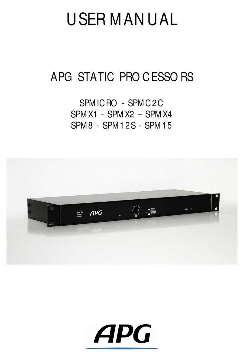
APG SPWX User manual

USER GUIDE
STAGE MONITOR PROCESSOR SPWX

Processor SPWX 1
SUMMARY
SAFETY INSTRUCTIONS 2
THANKS AND UNPAKING 3
IMPORTANT SAFETY INFORMATION 3
FUNCTIONALITIES 4
GENERAL INTRODUCTION 4
BLOCK DIAGRAM OF SPWX 4
WIRING 5
TECHNICAL SPECIFICATIONS 6
CONTROLS DESCRIPTION 7
FRONT PANEL 7
REAR PANEL 8

Processor SPWX 2
SAFETY INSTRUCTIONS
This symbol, wherever it appears, alerts
you to the presence of un-insulated
dangerous voltage inside the enclosure –
voltage that may be sufficient to
constitute a risk of shock.
This symbol wherever it appears, alerts
You to important t operating and
maintenance instructions in the
accompanying literature. Read the manual.
These symbols indicate that no part is available inside the device. Do not open the device. Do not try to troubleshoot.
Contact a qualified technician. Opening the device will void the warranty for no reason manufacturer. Do not wet the unit.
If liquid is spilled, immediately turn off the device and bring it to the distributor for repair. Unplug the unit during storms to
prevent damage.
INFORMATION ABOUT APPLIANCE SUPPLIED WITH POWERD CORD:
WARNING: APPLIANCE MUST HAVE GROUNDING
The conductors of the cable industry are identified as follows:
Green / Yellow Ground
Blue Neutral
Brown Phase
If the colors of the power cable do not match with the colors of the socket, please proceed as follow:
Green/Yellow wire be must be connected to the wire identified with E letter ground sign.
Blue wire must be connected to the black wire or the wire identified with N letter.
Brown wire must be connected to the red wire or the wire identified with L letter.
Warning: When no grounding exists, problems may appear with the appliance or the system it is connected to, in case of
high tension between casing and grounding. Serious injuries or death can occur in case of simultaneous contact with case
grounding.
FOR YOUR PROTECTION, PLEASE READ THE FOLLOWING:
WATER AND MOISTURE: The device should not be used near a water source (near a bathtub,
bowl, kitchen sink, in a wet basement or near a swimming pool, etc. ...). Be careful that no liquid can be enters the device
(some openings).
POWER SOURCE: The appliance should be connected to a power supply only of the type described in the operating
instructions or as marked on the appliance.
GROUNDING or POLARIZATION: Precautions should be taken so that the grounding and polarization are properly done.
REPAIRS: To avoid the risk of fire or electric shock, user should not attempt to troubleshoot the device out of the
instructions in the manual. In case of failure, contact a qualified technician.
ELECTROMAGNETIC COMPATIBILITY:
The device meets the requirements of the Declaration of Conformity.
This device may not cause harmful parasites.
This device supports any interference, even parasite that may cause malfunctions.
The use of this device in an electromagnetic field, however, must be avoided.
CONDUCTOR

Processor SPWX 3
UNPAKING
Thank you for choosing this processor APG. Please take a moment to read the contents of this
manual.
All APG Products are carefully designed in order to provide performance and reliability of high level.
Do not hesitate to contact us or visit our website for more information on APG products.
Website: www.apg-audio.com
Email: contact@apg.tm.fr
Unpacking PROCESSOR SPWX APG
Once the product is out of the box, please check that product is not damaged.
If the unit is damaged, notify the carrier and make the claim.
Please keep the packaging for future use.
Instructions
This manual provides a detailed description of all functions of the SPWX processor.
IMPORTANT SAFETY INFORMATION
Please read and keep these instructions and warnings. Follow all warnings and all instructions.
Do not open the device.
Maintenance of internal components must not be done by user.
Service and maintenance must be carried out by qualified personnel.
This device must be connected to a grounded power outlet.
Avoid cord to be stepped on and protect device against damage.
Pay particular attention to plugs.
Only use attachments / accessories specified by the manufacturer.
Have the product controlled if damaged (power cable or plug damage, for example), in case
of infiltration of liquid or objects into the case, if the unit has been exposed to rain or
humidity, does not operate normally or has been dropped.

Processor SPWX 4
FUNCTIONALITIES
GENERAL INTRODUCTION
The processor static APG SPWX is designed to optimize the operation of DX12 & DX15 speakers and
subwoofers SB115, SUB138P & SUB238S in the applications of a floor or side fill or drum fill with sub.
It integrates all the functions of electronic filtering to optimize the frequency response of speakers
and subsonic protection.
This processor offers 4 channels, each one includes: a resonant high pass filter, a low pass filter, a
shelving filter and three cells of parametric equalization. The "sub" output includes a resonant high
pass filter, a low pass Linkwitz Riley 4th order (24 dB / octave).
The connection is made with a slope of 24 dB / octave with a cutoff frequency of 110Hz between
speakers and subwoofer.
This processor operates in two modes:
4 independent channels
2 full range monitoring channels and on 2-way active mono channel (mid/hi + sub)
BLOCK DIAGRAM OF SPWX

Processor SPWX 5
WIRING
The processor is the last item in the chain before the amplifier.
The processor receives input signals from the console or effect rack. Its outputs are directly
connected to amplifiers.
1°) Mode with 4 channels:
2°) Mode with SUB:
NOTE : in this mode, input 3 does not operate, only the physical output is used for the sub processing

Processor SPWX 6
TECHNICAL SPECIFICATIONS
SPECIFICATIONS
Inputs:
Balanced XLR 3 pin female, Pin1 Ground
Nominal level +4 dBu
impedance: 18 kOhms
Outputs:
Balanced XLR 3 pin male, Pin1 Ground
Nominal level: 21 dBu
impedance 60 Ohms
FREQUENCY OF CONNECTION BETWEEN SPEAKER AND SUBWOOFER
DX12: 110Hz 24dB/octave
DX15: 110Hz 24dB/octave
OVERALL INFORMATION
Noise: 94 dBu (22Hz-22kHz)
THD less than < 0.1% (4 dBu, 1kHz)
Connectors: 3 pin XLR, Pin1 Ground
Consumption: 220/240V AC 15VA
PHYSICAL
Dimensions: 482x220x44 (mm)
Net weight: 4,5kg
Front panel: steel 3 mm
Finish : epoxy grey paint

Processor SPWX 7
CONTROLS DESCRIPTION
FRONT PANEL
1) Hard-Bypass (1 +2) / (3 +4): This feature pairs to disable the processor, to isolate the amp and
can be used without other forums have changed the internal wiring.
2) DX15/DX12: This function is used to select the speakers DX15 or DX12.
3) Stand / Floor:
Pressing this key switches the mode "stand" when speakers are set up on a stand. Then, the
frequency response is useful for high precision vocal reproduction and medium throw
application (distributed sound system).
By disabling this key switches the mode "floor” when speakers are coupled with the floor. In
this case the effect of the coupling with the floor allows all kind of full range musical
application stage and near field monitoring.
4) HF EQ: This knob controls the clarity of the system to change the spectral balance of the system
depending on the acoustic environment, listening distance and coupling effects.
5) Signal LED: This LED is used to display the presence of a signal higher than - 20 dB on each output.
6) With / off Sub (3&4 only): Pressing this key activates a subwoofer channel on the output of
channel 3 and inserts a high-pass filter in the response of channel 4 for the crossover between speaker
and subwoofer.
7) Sub Level: This knob controls the sub level when the function 6° is activated. A centre position, the
trigger materializes the nominal level of the subwoofer. The range is from infinite attenuation to 6 dB
gain. It is advisable to adjust the subwoofer channel level after installation of speakers.
8) Power: This LED indicates the presence of voltage. The processor can be left running continuously;
there is no power switch.
1
4
7
8
2
3
5
6

Processor SPWX 8
REAR PANEL
9) Power supply connector : The base area is the IEC standard, the centre pin is grounded. For
security reasons, it must always be connected.
10 °) The rear panel has 4 channels. Each channel has an input and an audio output.
11 °) Audio input connector XLR female 3-pin: These connectors are wired as completely
symmetrical: pin 1: ground, pin 2: hot, Pin 3: COLD. Pin 1 of the two inputs is connected directly to
the chassis and feed the signal processing chains. You can use them with an unbalanced source by
connecting pin 3 to ground lug to the source.
12 °) Audio outputs Connector XLR male 3-pin: These connectors deliver the balanced outputs
processed signals and they are wired as follows: pin 1: ground, pin 2: hot, Pin 3: COLD. You can use
them with an unbalanced source by connecting pin 3 to ground lug to the source.
Note: pin 1 of the output is decoupled from the mass for audio frequencies but is grounded to
ensure the rejection of radio frequencies, ensuring electromagnetic compatibility of the processor.
Result: The amplifier connected to the processor provides grounding the cable shield connected to
their inputs.
Note: The processor uses a circuit ground loop eliminator. If a parasite snoring occurs in a facility, it is
not due to a ground loop.
During use of the subwoofer (activation of function 6) With Sub), the output of channel 3
is used for the Sub signal (the input 3 is deactivated). For speakers DX12 or DX15, only
input and output of channel 4 are activated.
The main fuse must be replaced only with the same type and value.
250V/0,160A Temp
9
10
12
11

APG FRANCE-19 Bis Rue des Ecoles - Site Valnor ZI Haute 95500 Le Thillay -RCS Pontoise 451935084
Tel: +33(0)1.30.18.92.70 Fax: +33(0)1.30.18.92.71 –E-mail:[email protected]m.fr –Site: www.apg-audio.com
Table of contents
Other APG Computer Hardware manuals