Aphex 188 User manual

Model 188

188
Remote Controlled 8 Channel Microphone
Preamplifier
Instruction Manual
P/N 188-3200
Preliminary Rev 1
Released 01/23/09
Manufactured by
Aphex Systems Ltd.
11068 Randall St.
Sun Valley, CA 91352
USA
Produced by Wayne LaFarr
Copyright 2009 Aphex Systems Ltd. All rights reserved.
Page 1Aphex Systems Ltd. Model 188

188
Safety Declarations
CAUTION: For protection against electric shock, do not remove the cover. No user serviceable parts inside.
WARNING: This equipment has been tested and found to comply with the limits for a Class A digital device pursuant to Part 15
of the FCC Rules. These limits are designed to provide reasonable protection against harmful interference when the equipment is
operated in a commercial environment. This equipment generates, uses, and can radiate radio frequency energy and, if not installed
and used in accordance with the operating guide, may cause interference to radio communications. Operation of this equipment
in a residential area is likely to cause interference in which case the user will be required to correct the interference at his own
expense.
The user is cautioned that changes and modications made to the equipment without approval of the manufacturer could void the
user’s authority to operate this equipment.
It is suggested that the user use only shielded and grounded cables to ensure compliance with FCC Rules.
|
A MESSAGE FROM THE PRESIDENT
Dear Aphex Customer,
Congratulations on your purchase of the Model 188 Remote Controlled Microphone Preamplier. Years of
research and development were required to overcome the hurdles that similarly purposed products do not even
address. Since the introduction of our rst remote controlled preamplier, the Model 1788 and its successor the
Model 1788A, we have learned much from hundreds of high prole applications. While the Model 188 does not
have all the features that are in the Model 1788As, it does have the primary functionality and performance at a
fraction of the cost.
The Model 188 was designed primarily as an integral part of the Anaconda Digital Snake System. Our listening
tests as well as tests by respected engineers have conrmed that the Model 188 is an excellent sounding pre-
amplier in its own right. The value of it is so much higher because it is so easily remote controllable. It can be
controlled by the Model 1788AR-C hardware remote controller, PC or MAC software.
We are extremely pleased that you have joined the elite of the audio world.
Very truly yours,
Marvin Caesar
President
Page 2Aphex Systems Ltd. Model 188

188
Table of Contents
1.Introduction
2.Quick Start
Front Panel LCD Display and Rotary Encoder/Switch
Front Panel Screens
3. Rear Panel
4. Model 188 block diagram and signal ow
5. Installation
6. Functions in Detail
Page 3Aphex Systems Ltd. Model 188

188
Why remote controlled preampliers?
Locating the mic preamplier as close as possible to the microphone eliminates the long cable runs at mic level.
Induced noise would be amplied. In addition, capacitance and resistance in that long cable run would affect
the performance of the microphone.
Transformer splitters are only effective in isolating ground. The impedance from all the preampliers connected
to the system as well as the cabling combine to load down the output of the microphone. For example- most
microphones are designed to drive between 1200 and 1500Ω loads. If a microphone is connected to three pre-
ampliers, the input impedance is 500Ω. The sonic effects are reduced frequency and transient response, and
higher noise. The increase in audio quality when the microphone is driving an ideal load is dramatic. The 188
acts like an active splitter with one analog and two digital outputs..
Once you have line level signal from the remote preamplier make sure that you do not put that signal through
another preamplier. Almost all consoles switch in a pad in front of their preampliers and label the input as
‘line’. If the trim pot still controls level, you are going through a preamplier. It is best to use an insert return
for an analog line level signal. You will be amazed at how much better everything sounds!
If you are using a digital console without any analog input other than a preamplier, we strongly recommend
converting the output of the remote preamplier to digital. We designed a high quality A/D into the Model 188
for that purpose.
The Model 188 and its big brother the Model 1788A fulll all the requirements for a remote controlled pream-
plier- great audio, easy to control, no glitches, pops or zipper noise, and multiple outputs.
Introduction
Page 4Aphex Systems Ltd. Model 188

188
Quick Start
Rotary Encoder and Switch
Rotate the encoder clockwise or counterclockwise to scroll between screens. Press the en-
coder to make the cursor appear within a screen. Rotate the encoder to move the cursor to
the value or status to be changed and press to select, the cursor will start blinking. Rotate
the encoder to change the value or status. Press the encoder to save the value or status.
The rst screen shows the rmware version that is loaded into the
Model 188. It is a good idea to check the Aphex website occasion-
ally to see if there are any updates. Updating the rmware is cov-
ered in section----
Start Up
Page 5Aphex Systems Ltd. Model 188

188
This screen shows a twelve segment peak level meter for each channel.
When there is an overload the clip on that channel is indicated with a “!”.
When the unit receives a command from a remote controller, “RC” will
light for half a second. We recommend that this screen be selected when
set up is complete.
Metering
There is one screen for each of the eight channels. Each screen indicates
Channel number, gain, status for Polarity Reverse, Pad, Low Cut Filter, and
Phantom Power functions. A check mark under the function indicates that it
is active. A dash indicates that it is not active.
The Input Gain is adjustable from 26 to 65dB.
Channel Status and Input Gain
Page 6
Aphex Systems Ltd. Model 188

188
Pressing the encoder will make the cursor appear under source selection- either “Int”
(internal), “Ext” (external), or “Ext SMUX”. If the source is set to Internal move the
cursor under the sample rate. Press the encoder in and then rotate to the desired value
(44.1, 48, SMUX 44.1, SMUX 48, SMUX 88.2 or SMUX 96kHz). The rate that is
selected will appear on the Word Clock output. If the source is set to External, the
sample rate will appear in the screen if there is a valid clock input.
Clock Source
In order to safeguard against unwanted changes to the system conguration, the
rotary encoder must be pressed in for several seconds. The system conguration
includes clock source, format and sample rate, display contrast, Net Number assign,
DHCP/IP select and system congure exit. The rst screen after the encoder is held
in is Clock Source.
System Congure
Page 7Aphex Systems Ltd. Model 188

188
Press encoder in and then rotate clockwise for more contrast,
counter-clockwise for less contrast.
Contrast Adjust
The Net Number identies the particular unit within a system.
Note: There must be only one unit assigned to one Net Number
otherwise the Remote Control and metering will be unpredict-
able.
Net Number
DHCP requires a router which will ‘serve’ an IP address dynamically. Fixed IP forces the address
that is programmed into the unit and modied by the Net Number. The letter ‘D’ will be in front of
the IP address when DHCP is selected and the letter ‘F’ will be in front of the IP address when Fixed
IP is selected. The xed IP addresses range from 192.168.1.64 for Net Number 001 to 192.168.1.192
for Net Number 128. If these addresses are not compatible with your network, please contact Aphex.
Note: Power must be cycled off and on to commit these changes.
DHCP/FIXED IP
Page 8Aphex Systems Ltd. Model 188
188
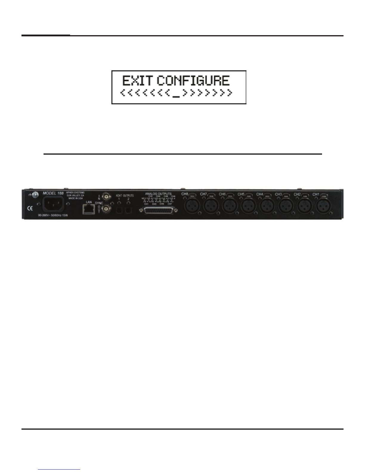
Exit Congure
Press the encoder in and the display will change to the
metering screen.
Rear Panel
Microphone Inputs
Each microphone input is a locking female XLR (pin #1 ground, pin # 2 ‘+’ and
pin # 3 ‘-‘). Maximum input level is +21dBu with Pad engaged and the input
gain at 26dB.
Line Level Output
The channel outputs appear on a 25 pin D-Sub female connector using the Tas-
cam analog standard pin out. Maximum output level is xed at +21dBu. Note:
The analog output of each channel can be internally ( See page 15) selected to
be either ‘post’ or ‘pre’ variable gain amplier. In the ‘post’ mode the output
will be affected by the Pad, Low Cut and Polarity Reverse as well as the vari-
able gain amplier. In the ‘pre’ mode the output will be affected by everything
except the variable gain amplier. The ‘pre’ mode is useful to feed a monitor
console.
ADAT Outputs 1 and 2
Each Toslink connector will output standard ADAT (audio channels 1 through
8) when SMUX is not selected. When SMUX is selected ADAT Output 1 will
have audio channels 1, 2, 3 and 4; and ADAT Output 2 will have audio channels
5, 6, 7 and 8.
Page 9Aphex Systems Ltd. Model 188
Other manuals for 188
1
Table of contents
Other Aphex Amplifier manuals

Aphex
Aphex 1788 User manual

Aphex
Aphex HeadPod 454 User manual

Aphex
Aphex CHANNEL User manual

Aphex
Aphex J PRE 500 User manual

Aphex
Aphex CHANNEL User manual

Aphex
Aphex CHANNEL User manual

Aphex
Aphex DUAL RPA 500 User manual

Aphex
Aphex 120 User manual

Aphex
Aphex 120A User manual

Aphex
Aphex Solution Deliver 207 User manual

Aphex
Aphex 1100 MkII User manual

Aphex
Aphex HeadPod 4 User manual

Aphex
Aphex 188 User manual

Aphex
Aphex 661 User manual

Aphex
Aphex 1788 Installation and operating instructions

Aphex
Aphex PROJECT 500 User manual

Aphex
Aphex Thermionics 1100 User manual

Aphex
Aphex 207D User manual

Aphex
Aphex 1788A User manual

Aphex
Aphex HEADPOD 4 User manual


