Aphex PROJECT 500 User manual

Owner’s Manual
PROJECT 500
™
CLASS A MIC PRE, OPTICAL COMPRESSOR,
DUAL BAND EQ
500 SERIES CHANNEL STRIP MODULE
Page 2
SAFETY DECLARATIONS
WARNING: Do not place objects containing liquid on this unit as
it is not designed to protect against spillage. Do not expose this
unit to dripping or splashing of liquids as the unit is not designed
to protect against these occurrences.
WARNING: The PROJECT 500 has been tested and meets the FCC,
CE and European Union rules, regulations, and guidelines for use.
Do not attempt to modify or change the PROJECT 500, as this
could void the regulatory compliance, which would place you at
risk of losing your authority to operate the PROJECT 500.
WARNING: Do not place objects on top of this unit if they weigh
more than 10 pounds.

Page 3
SAFETY DECLARATIONS
This equipment has been tested and found to comply with the limits
for a Class B digital device, pursuant to part 15 of the FCC rules.
These limits are designed to provide reasonable protection against
harmful interference in a residential installation. This equipment
generates, uses and can radiate radio frequency energy and, if not
installed and used in accordance with the instructions, may cause
harmful interference to radio communications. However, there is
no guarantee that interference will not occur in a particular instal-
lation. If this equipment does cause harmful interference to radio
or television reception, which can be determined by turning the
equipment off and on, the user is encouraged to try to correct the
interference by one or more of the following measures.
1. Reorient or relocate the receiving antenna.
2. Increase the separation between the equipment and receiver.
3. Connect the equipment into an outlet on a circuit different from
that to which the receiver is connected.
4. Consult the dealer or an experienced radio/TV technician for help.

Page 4
TABLE OF CONTENTS
1.0 INSTALLATION 5
2.0 INTRODUCTION 6
3.0 CONTROLS & INDICATORS 6
3.1 Trim Control 6
3.2 Compressor On/Off Button 6
3.3 Gain Reduction LED 7
3.4 Ratio Control 7
3.5 Post Button 7
3.6 Cut/Boost Knobs 8
3.7 Frequency Knobs 8
3.8 Output Knob 8
3.9 Phase Reverse Button 8
3.10 High Pass Filter 8
3.11 Phantom Power Button 8
3.12 Instrument Input 8
4.0 SERVICE & WARRANTY 9
4.1 Service Information 9
4.2 Service Information 10
5.0 SPECIFICATIONS 10
Page 5
1. Turn off and unplug your 500 series rack frame. Inspect the
card slot you intend to use to make sure that it is clean and free
of any debris.
2. Before removing your Project 500 from its box, discharge any
static electricity buildup you may have by touching your 500
series rack.
3. Pull your Project 500 module out of its box and carefully slide
it into place in the designated opening. Sight down the back of
the module (use a flashlight if necessary) and ensure the card
edge connector is aligned to seat into the card slot of the frame.
4. Firmly and evenly push the Project 500 module into place
until it is positively seated in the card slot.
5. Use the 2 thumb screws in the module to mount the Project
500 front panel to the 500 series rack. These screws have a
pretty tight fit; please be careful not to cross thread.
6. Plug your 500 series rack back into the AC source and power
up your rack. Your Project 500 will automatically power up
with your 500 series rack.
1.0 INSTALLATION

Page 6
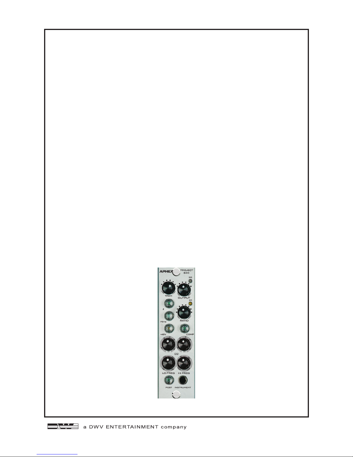
2.0 INTRODUCTION
The Project 500 is a 500 Series channel strip module that includes
a Class-A mic pre, an optical compressor and a two-band equal-
izer. The optocoupler was designed to be as fast as possible and is
produced exclusively for Aphex. The inputs and outputs are elec-
tronically balanced.
• Class-A mic pre design from the popular
Aphex Project Channel.
• The optical compressor is extremely trans-
parent and can be assigned to come before
or after the EQ.
• Two bands of semi-parametric EQ with
overlapping frequencies.
• 10Mohm instrument input.
• 48V phantom power, 75Hz HPF and Phase
reverse buttons are provided.
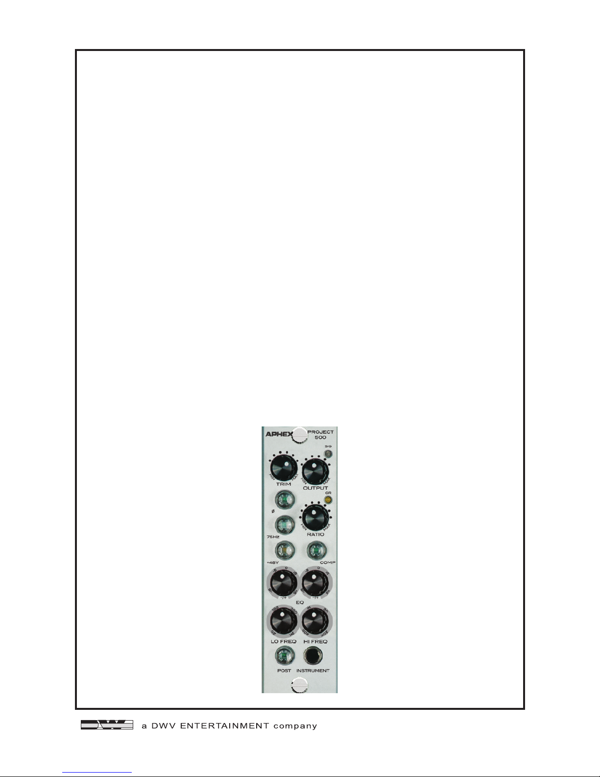
3.0 CONTROLS & INDICATORS
3.1 TRIM CONTROL
The Trim knob controls the amount of input
gain to the mic pre. The Signal LED will light
green when an input signal is detected. It will
turn yellow as the input signal increases and
will turn red when the input is being clipped.
3.2 COMPRESSOR ON/OFF BUTTON
The Compressor on/off button activates or
deactivates the compressor function.
Page 7
3.3 GAIN REDUCTION LED
The Gain Reduction LED provides visual feed- back as to the
amount of gain reduction. The LED will glow yellow when gain
reduction occurs. The brighter it glows, the more gain reduction
is taking place.
3.4 RATIO CONTROL
The Ratio knob controls the decibel relation- ship between the
amount of increase in input signal vs. the amount of increase
in output signal. All the way to the left, the output will increase
approximately 1dB for every 1.5dB increase in input, providing a
very light and smooth compression. All the way to the right, the
output will increase approximately 1dB for every 6dB increase in
input, providing a more heavily compressed sound.
3.5 POST BUTTON
The Post button determines if the compressor function comes
before or after the equalizer function. When the button is not
lighted the compressor comes before the equalizer. When the
button is lighted the compressor comes after the equalizer.

Page 8
EQUALIZER CONTROLS
3.6 CUT/BOOST KNOBS
Each EQ band can be cut or boosted by
15dB.
3.7 FREQUENCY KNOBS
The low frequency band knob allows set-
tings from 20Hz to 2kHz.
The high frequency band knob allows set-
tings from 1kHz to 20kHz.
3.8 OUTPUT KNOB
The Output level knob determines the over-
all output level of the module.
3.9 PHASE REVERSE BUTTON
The Phase Reverse Button shifts the input
signals phase by 180 degrees.
3.10 HIGH PASS FILTER
The HPF rolls of frequencies below 75Hz
at 12dB per octave. This function comes
before the compressor and equalizer func-
tions.
3.11 PHANTOM POWER
The phantom power button supplies 48V to condenser micro-
phones.
3.12 INSTRUMENT INPUT
The 10Mohm instrument input allows a direct input to the Project
500 from an electric guitar or bass. This input overrides the XLR
input on your 500 series receiving frame.

Page 9
PERIOD
One year from date of purchase.
SCOPE
All defects in workmanship and materials. The following are not covered:
a. Voltage conversions.
b. Units on which the serial number has been defaced, modified, or removed
c. Damage or deterioration:
1. Resulting from installation and/or removal of the unit.
2. Resulting from accident, misuse, abuse, neglect, unauthorized
product modification or failure to follow instructions contained
in the User’s Manual.
3. Resulting from repair or attempted repair by anyone not
authorized by Aphex.
4. Occurring from shipping (claims must be presented to shipper).
WHO IS PROTECTED
This warranty will be enforceable by the original purchaser and by any subsequent
owner(s) during the warranty period, so long as a copy of the original Bill of
Sale is submitted whenever warranty service is required.
WHAT WE WILL PAY FOR
We will pay for all labor and material expenses for covered items. We will pay
return shipping charges if the repairs are covered by the warranty.
LIMITATION OF WARRANTY
No warranty is made, either expressed or implied, as to the merchantability
and fitness for any particular purpose. Any and all warranties are limited to
the duration of the warranty stated above.
EXCLUSION OF CERTAIN DAMAGES
Aphex’s liability for any defective unit is limited to the repair or replacement
of said unit, at our option, and shall not include damages of any other kind,
whether incidental, consequential, or otherwise.
Some States do not allow limitations on how long an implied warranty lasts
and/or do not allow the exclusion or limitation of incidental or consequential
damages, so the above limitations and exclusions may not apply to you.
This warranty gives you specific legal rights, and you may also have other
rights which vary from State to State.
4.0 SERVICE & WARRANTY
4.1 LIMITED WARRANTY

Page 10
4.2 SERVICE INFORMATION
If it becomes necessary to return this unit for repair, you must first contact
Aphex for a Return Authorization (RMA number), which will need to be
included with your shipment for proper identification. If available, repack
this unit in its original carton and packing material. Otherwise, pack the
equipment in a strong carton containing at least 2 inches of padding on
all sides. Be sure the unit cannot shift around inside the carton. Include a
letter explaining the symptoms and/or defect(s). Be sure to reference the
RMA number in your letter and mark the RMA number on the outside of the
carton. If you believe the problem should be covered under the terms of the
warranty, you must also include proof of purchase. Insure your shipment and
send it to APHEX at the address provided with the RMA.
INPUT
Type:
Impedance:
Unbalanced:
Nominal Level: Maximum
Level:
CMRR:
OUTPUT
Impedance:
Nominal Level:
Maximum Level:
AUDIO
Frequency Response:
Dynamic Range:
THD:
IMD:
OPERATING LEVEL
Switch Setting: +4dBu
Transformerless, active balanced
40KΩ
20KΩ
+4dBu
+24dBu
>40dB
110Ω
+4dBu
+24dBu Unloaded
+0.5dB 10Hz-38KHz
120dB
10Hz - 22kHz @ max output
.0003%
10Hz - 22kHz 0 max output,
.0007%
5.0 SPECIFICATIONS
CONNECTOR PINOUT
1 CHASSIS GROUND
2 OUTPUT + (+4 LEVEL)
3 (unused)
4 OUTPUT - (+4 LEVEL)
5 COMMON
6 LINK
7 (unused)
8 INPUT- (+4 LEVEL)
9 (unused)
10 INPUT+ (+4 LEVEL)
11 (unused)
12 +16VDC
13 POWER SUPPLY COMMON
14 -16VDC
15 (unused)
Table of contents
Other Aphex Amplifier manuals

Aphex
Aphex 188 User manual

Aphex
Aphex 188 User manual

Aphex
Aphex 207D User manual

Aphex
Aphex 1100 MkII User manual

Aphex
Aphex HeadPod 4 User manual

Aphex
Aphex Thermionics 1100 User manual

Aphex
Aphex HEADPOD 4 User manual

Aphex
Aphex 1788 Installation and operating instructions

Aphex
Aphex CHANNEL User manual

Aphex
Aphex Solution Deliver 207 User manual


