Aplex OPC-5XX7 User manual

OPC-5XX7 User Manual 1
OPC-5XX7 Open Frame PC
User Manual
Release Date _ Revision
Feb. 2012 V1.0
®2011 Aplex Technology, Inc. All Rights Reserved. PublishedinTaiwan
Aplex Technology, Inc.
15F-1, No.186, Jian Yi Road, Zhonghe District, New Taipei City 235, Taiwan

OPC-5XX7 User Manual 2
Warning!___________________________________
This equipment generates, uses and can radiate radio frequency energy and if not installed and
used in accordance with the instructions manual, it may cause interference to radio communications.
It has been tested and found to comply with the limits for a Class A computing device pursuant to
FCC Rules, which are designed to provide reasonable protection against such interference when
operated in a commercial environment. Operation of this equipment in a residential area is likely
to cause interference in which case the user at his own expense will be required to take whatever
measures may be required to correct the interference.
Disclaimer
This information in this document is subject to change without notice. In no event shall Aplex Technology
Inc. be liable for damages of any kind, whether incidental or consequential, arising from either the use or
misuse of information in this document or in any related materials.
Electric Shock Hazard – Do not operate the machine with its back cover removed. There are
dangerous high voltages inside.

OPC-5XX7 User Manual 3
Packing List
Accessories (as ticked) included in this package are:
□ AC power cable
□ Driver & manual CD disc
□ Other.___________________(please specify)
Safety Precautions
Follow the messages below to prevent your systems from damage:
◆ Avoid your system from static electricity on all occasions.
◆Prevent electric shock. Don‘t touch any components of this card when the card is
power-on. Always disconnect power when the system is not in use.
◆Disconnect power when you change any hardware devices. For instance, when you
connect a jumper or install any cards, a surge of power may damage the electronic
components or the whole system.

OPC-5XX7 User Manual 4
Table of Contents______________________
Warning!…………………………………………………………………………….……..….2
Disclaimer………………………………………………………………….…………………2
Packing List…………………………………………………………………………………..3
Safety Precautions…………………………………………………………………………..3
Chapter1 GettingStarted
1.1 Features…….……………………………………….……………………..6
1.2 Specifications……………………………...………………………….......6
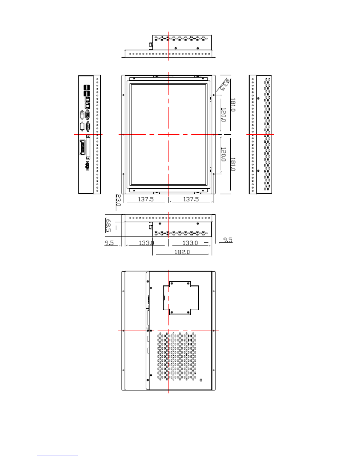
1.3 Dimensions……..………………….…………………………….…..8
1.4 Installation of HDD…….………………………………………..12
1.5 Brief Description…………………………………………………….……14
Chapter2 Hardware
2.1 Mainboard specifications.…….……………………………………..…..15
2.2 Installations……………………………….…………………....................21
2.3 Onboard Jumpers and Port Pin outs……………………………….....22
Chapter3 BIOSSetup
3.1 Operations after POST Screen................................................32
3.2 Standard CMOS Features...............................................34
3.3 Advanced BIOS Features.....................................................37
3.4 Advanced Chipset Features Setup............................... 40
3.5 Integrated Peripherals................................................................... 44
3.6 Power Managements Setup................................................. 50
3.7 PnP/PCI Configurations Setup...................................................... 53
3.8 PC Health Status…................................................................ 55
3.9 Load Fail-Safe/Optimized Defaults.............................................. 56
3.10 Set Administrator/User Password....................................... 58
3.11 Save & Exit Setup……………............................................. 59
3.12 Exit Without Saving……………………………………………………… 60
Chapter4 InstallationofDrivers
4.1 Intel Chipset Driver.…………………………...…………………………62
4.2 Intel Graphics Media Accelerator Driver...………………………..66

OPC-5XX7 User Manual 5
4.3 Realtek Gigabit LAN Driver……………………………..……………….70
4.4 Realtek HD Driver Installation…….………..……………………….……73
Chapter5 TouchScreenInstallation
5.1 Introduction to Controller Board..…………………………..……………76
5.2 Windows 2000/XP USB Driver Installation for 6000 Boards………..….76
Figures
Figure 1.1: OPC-5087 Dimensions……………………………………..…....8
Figure 1.2: OPC-5127 Dimensions……………………………………..…...9
Figure 1.3: OPC-5157 Dimensions………….………………………………10
Figure 1.4: OPC-5197 Dimensions…...…….….……………………………11
Figure 1.5: Front View of OPC-5157….……………………………14
Figure 1.6: Rear View of OPC-5157….……………………………14
Figure 2.1: Mainboard Overview………………………………………….....15
Figure 2.2: Mainboard Dimensions……………………………………….....16
Figure 2.3: Connector and Jumper Locatios…………………………….....18
Figure 2.4 Installation of Memory Module…………………………..……21
Figure 5.1 Birdeye’s View of Control Board…………………………………76

OPC-5XX7 User Manual 6
Chapter1 System
1.1 Features
Open frame, fanless design
8”/12.1”/15”/19” TFT LCD with resolution of 800x600/1024x768/1280x1024
Intel Atom N270 1.6GHz processor, FSB 533MHz
Option resistive touch screen
Wide range DC 11~32V power input for option
1.2 Specifications
System
Processor Intel Atom N270 1.6GHz, FSB 533MHz
System Memory 1GB DDR2 SODIMM 533MHz up to 2GB, default 1GB
System Chipset Intel 945GSE+ICH7M
External I/O Port OPC-5087
4 x USB 2.0
2 x GbE RJ-45 Lan port
1 x DB-15 VGA
1 x DB-9 COM1 RS-232
1 x DB-9 COM2 RS-232/422/485 (default: RS-232)
1 x DB-9 (optional RS-232/422/485 port, default: none)
1 x 3 Pin terminal block DC Power input
1 x 4 Pin terminal block, 2 Pin for power on/off connector, 1 Pin for
ground, 1 Pin as VCC
OPC-5127/5157/5197
4 x USB 2.0
2 x GbE RJ-45 Lan port
1 x DB-15 VGA
1 x DB-9 COM1 RS-232
1 x DB-9 COM2 RS-232/422/485 (default: RS-232)
1 x DB-9 (optional RS-232/422/485 port, default: none)
1 x 3 Pin terminal block DC Power input
1 x 8 Pin terminal block, 2 Pin for power on/off connector, 1 Pin for
ground, 1 Pin as VCC, and 2 in/out DIO
Storage 1 x 2.5” SATA HDD, 1 x internal CF slot (OPC-5087)
1 x 2.5” SATA HDD, 1 x internal CF slot, external slot for option

OPC-5XX7 User Manual 7
(OPC-5127/5157/5197)
OS Support Windows XP Professional, XP Embedded, Windows Embedded Standard
7, Win CE5.0, Win CE6.0
LCD
Display Type TFT-LCD
Max. Resolution 800x600 (OPC-5087/5127)
1024x768 (OPC-5157)
1280x1024 (OPC-5197)
Max. Color 262K (OPC-5087/5127)
16.2M (OPC-5157)
16.7M (OPC-5197)
Luminance (cd/m2) 350 (cd/m2)(OPC-5087/5127/5157)
300 (cd/m2)(OPC-5197)
View Angle H:130° / V:110° (OPC-5087) H:125° / V:140° (OPC-5157)
H:140° / V:110° (OPC-5127) H:170° / V:160° (OPC-5197)
Backlight Lifetime 50,000hrs
Touch Screen
Type Resistive Touch (Option)
Light Transmission 80%
Power Supply
Power Input DC 12V, DC 11~32V for option
Mechanical
Construction Steel molding housing
IP Rating None
Mounting Panel Mount
Dimension
(WxHxD)
222 x 176 x 64.6 mm (OPC-5087)
300 x 230 x 68.5 mm (OPC-5127)
362 x 266 x 68.5 mm (OPC-5157)
426 x 336 x 74.5 mm (OPC-5197)
Environmental
Operating Temperature 0~40 ゚C without fan / 0~60 ゚C with fan
Storage Temperature -20~60 ゚C
Storage Humidity 10~90% @40℃non-condensing
Certificate CE/FCC Class A

OPC-5XX7 User Manual 8
1.3 Dimensions
Figure 1.1: Dimensions of the OPC-5087

OPC-5XX7 User Manual 9
Figure 1.2: Dimensions of the OPC-5127

OPC-5XX7 User Manual 10
Figure 1.3: Dimensions of the OPC-5157

OPC-5XX7 User Manual 11
Figure 1.4: Dimensions of the OPC-5197

OPC-5XX7 User Manual 12
1.4 Installation of HDD
Step 1
There are 4 screws to deal with when enclosing
or removing the HDD chassis.
Step 2
Get the HDD and screw to the bracket with the
four screws as shown by the arrows in the
picture.
Step 3
Connect the cable to the HDD as shown in the
picture, making sure the red stripe of the cable
is rightly positioned.

OPC-5XX7 User Manual 13
Step 4
That’s how it should look after it has been
installed.

OPC-5XX7 User Manual 14
1.5 Brief Description of the OPC-5XX7
The OPC-5XX7 is a power-optimized and delivers robust performance-per-watt for embedded open
frame HMI. The powered by an Atom N270 processor and comes with a compact flash slot, 2.5-inch
hard disk drive, DDR2 memory, 3 COM ports, 2 Ethernet, DC input, and 4 USB ports. The unit
supports Windows XP Professional and XP Embedded, fanless touch panel computer is ideal for use
as Web Browser, Terminal and HMI at all levels of automation control.
Figure 1.5: Front View of OPC-5157
Figure 1.6: Rear View of OPC-5157

OPC-5XX7 User Manual 15
Chapter2 Hardware
2.1 Mainboard Specifications
Figure 2.1: Mainboard Overview

OPC-5XX7 User Manual 16
Figure 2.2: Mainboard Dimensions

OPC-5XX7 User Manual 17

OPC-5XX7 User Manual 18
Figure 2.3: Connector and Jumper Locations

OPC-5XX7 User Manual 19
Mainboard Specifications
Board Size 165 x 115mm
CPU Support Intel Atom N270 1.6 GHz with 533MHz FSB
Chipset Intel 945GSE + Intel ICH7M
Memory Support 1x200pin 533/400MHz DDR2 SO-DIMM support, up to 2GB
SDRAM
Graphics Intel Graphics Media Accelerator 950VGA integrated in Intel
945GSE
18-bit dual-channel LVDS integrated in Intel 945GSE
18/24 bit dual-channel LVDS support by Chrontel CH7308B
1 x DB15 Female connector for external
Super I/O Winbond W83627UHG
BIOS Award BIOS
Storage 2 x SATA Connector
1 x Compact Flash II Slot
1 x 44-pin IDE Connector
Network
2 x Gigabit Ethernet Port by RJ45 with LED indicators - Ethernet
controller :
2 x PCIe by one bus Realtek 8111D
USB 4 x USB 2.0 stack port for external
2 x USB 2.0 header for internal
Serial
1 x RS232 port, DB9 connector for external (COM1), pin 9
w/5V/12V/Ring select
1 x RS232/422/485 (Full-duplex) select header for internal
(COM2), default RS232
4 x RS232 header for internal (COM3 – COM6)
Digital I/O 8-bit digital I/O by header
4-bit digital Input
4-bit digital Output
Battery Support CR2477 battery by 2-pin header
Audio Support Audio via Realtek ALC662 HD audio decoder
Support Line-in, Line-out, MIC by 2x5-pin header
Printer 1x LPT port by 2x13-pin header
Keyboard
/Mouse
1x PS2 keyboard/mouse by 1x6 -pin wafer connector

OPC-5XX7 User Manual 20
Expansion Bus 1x PC 104+ connector (PCI master 4, jumper for +3.3V & 5V
select)
1x PCIe ( PCI-e 1x +SMBUS+USB2. 0 ) mini card
Power
Management
DC12V input
1 x 2x2-pin power input connector
Front I/O by 2x5-pin header
Power on/off switch
Reset switch
Power LED status
HDD LED status
Buzzer
Watchdog Timer Software programmable 1 – 255 second by Super I/O
External I/O port
1 x COM Port (COM1)
4 x USB 2.0 Ports (stack)
2 x RJ45 GbE Port (10/100/1000Mbps)
1 x VGA Port
Temperature Operating: 0 – 60 degree C
Storage: -20 – 80 degree C
Humidity 5% - 95%, non-condensing, operating
Power
Consumption 12V @1.4 5A (Intel N270 processor with 1GB DDR2 DRAM)
EMI/EMS CE/FCC class A
Table of contents
Popular Other manuals by other brands

DITEC
DITEC FACIL Installation and maintenance manual

Eaton
Eaton 150 VCP-WL Instructions for installation, operation and maintenance

Sony
Sony NTM-DA1 operating instructions

EHEIM
EHEIM Compact+ marine 1103 Series manual

ABB
ABB SPAA 341 C /E351 user manual

Wilo
Wilo SiFire Installation and operating instructions