Shinyei A01-16400 User manual

AccStick_004
Instruction Manual
Shock&Vibration data logger AccStick
Model:A01-16400
General warning
・No part of this instruction manual can be transferred nor reproduced without permission.
・Alterations to the contents of this instruction manual are reserved without notice for future
improvement.
・This instruction manual has been given the twice over to be doubly assured. However, we cannot be
responsible for any mistakes which might have occurred within its contents. Please inform us if you
have found obscurities, or wrong descriptions, skipped descriptions, or the like.
(HEAD OFFICE) B47-11, Katoridai, Tsukuba, Ibaraki, Japan,300-2657
Tel: +81-29-848-3571 FAX: +81-29-848-3572
(KOBE OFFICE) SHINYEI BLDG.5F,77-1,Kyomachi,Chuo-ku,Kobe,Hyogo,
650-0034,JAPAN
Tel: +81-78-392-6963 FAX:+81-78-332-1619
(NAGOYA OFFICE) Nishiki emuai BLDG. 6F, 1-7-39, Nishiki,Nakaku, Nagoya,
Aichi, 460-0003, Japan
Tel: +81-52-218-5472 Fax: +81-52-218-6110
URL: http://www.shinyei-tm.com
SHINYEI TESTING MACHINERY CO.,LTD


Contents
1. Precautions for operating the AccStick ·········································· - 1 -
2. About AccStick ································································ - 2 -
3. Devices and Tools Required for Measurement and Analysis and Precautions during
Handling and Operation ························································ - 3 -
3-1 Devices and tools required··················································· - 3 -
3-1-1 Recorder······························································· - 3 -
3-1-2 Software package······················································· - 3 -
3-2 Precautions during operation and handling····································· - 3 -
3-2-1 Operation and handling of AccStick········································ - 3 -
3-2-2 Data capturing software·················································· - 4 -
4. Operation ····································································· - 5 -
4-1 Battery···································································· - 5 -
4-2 Body······································································ - 6 -
4-3 Module for data connection / charging of battery ································ - 6 -
4-4 Data capacity ······························································ - 7 -
4-5 Data file··································································· - 7 -
5. Steps for installation of AccStick software······································· - 8 -
6. Measuring protocol ···························································· - 9 -
6-1 Configuring measuring conditions············································· - 9 -
6-2 From Measuring to Download ··············································· - 10 -
7. How to use the application software············································ - 11 -
8. Troubleshooting ······························································ - 15 -
9. AccStick Specifications ······················································· - 16 -
9-1 Specification sheet ························································ - 16 -
9-1-1 Hardware ····························································· - 16 -
9-1-2 Software······························································ - 16 -
9-2 Dimensions······························································· - 17 -
10. Product Warranty ····························································· - 17 -


- 1 -
1. Precautions for operating the AccStick
Precautions for operating the AccStick
Please keep this notice
Before using the AccStick, please read this notice and the AccStick’s instruction
manual thoroughly. We will not hold responsibility of any problems in relation to this
notice.
Problems resulting from the generation of heat, etc might occur if
you use misuse the AccStick. Note contents as follows.
Any sudden shocks, drops or hard strikes towards the Accstick unit may cause
body damage or generation of heat with the lithium polymer battery that might
catch fire. Be careful with this usage.
Do not store and operate the AccStick in any place with heats over 60℃or
extremely wet. These might be cause problems.
Prohibit
Do not expose AccStick to wet conditions as damage or heating the internal
battery might be occurred.
Prohibit
Do not open the casing or modify the AccStick. These might be cause damage or
other problems.
Prohibit
Prevent dust contamination at the connector part of the AccStick to prevent
damage to the connector and lithium battery from overheating.
Prohibit
Do not use the AccStick if you have found any errors to the instrument, or swelling
of the battery.
Prohibit
Always use the cable paired with the AccStick when charge the battery. Other
cables might cause any problems, overheating or damage to the battery.
Action
When you dispose of the AccStick, please confirm on how to dispose it from a
scrap company near you.
Action
Danger
Prohibit

- 2 -
2. About AccStick
Shock & vibration data logger, AccStick, consist of the Accstick unit and the customized software. 2
types of 3axis accelerometer, microcontroller, operational switch, and rechargeable battery, is
packed into one unit with an outer aluminum casing. Continuous measurements up to 3 days are
made possible.
Operation is as follows.
Configure the measuring conditions of unit via the specified software.
Install this unit to the object of which acceleration is to be measured.
After measuring, acceleration waveforms can be downloaded to your PC through the specified
software and converted to .csv file.
2-1 Features
2-1-1 Instrument
a) 3D MEMS accelerometer(±16G、±200G)
b) Small size, light weight
c) Built in Timer
d) Lithium polymer rechargeable battery(85mA/h)
e) Variable measuring mode(Trigger mode, Trigger level, Frame length, etc)
f) Viewing of output measured data via the specified software
2-1-2 Specific Software
a) Viewing data
b) Configuring of the measuring condition
c) Converting data (.csv file)
2-2 Application
a) Response acceleration measuring of the specimen for the product evaluation test
such as a shock test, a vibration test and a drop test
b) Motion capturing of humans or Robots
c) Vibration measuring of vehicles
d) Shock measuring of the operational handling
e) Other environmental measuring

- 3 -
3. Devices and Tools Required for Measurement and Analysis and
Precautions during Handling and Operation
3-1 Devices and tools required
3-1-1 Recorder
a) AccStick
3-1-2 Software package
a) Specific Software :the software can be downloaded on the website.
URL:http://www.shinyei-tm.com/product_AccStick.html
b) Personal computer※2
CPU :Core 2 Duo processor 2GHz or equivalent.
Main memory :1024MB minimum
Hard disc :available storage exceeding 3GB
Display :Color display applicable to Windows
USB communication port
Serial communication port
OS :Windows 7/10 (32bit/64bit)
3-2 Precautions during operation and handling
3-2-1 Operation and handling of AccStick
a) This unit is manufactured rigidly for shock and vibration measurement. However, if
excessive shock is applied to the unit by directly dropping it or the like, the unit may be
damaged. The unit may be damaged if an impact exceeding 10,000m/s2is applied.
b) Don’t expose the unit to conditions where water vapors or sea breeze etc., is present
directly to prevent any malfunctions with theAccStick.
c) The working temperature of this instrument is between 0℃~ +60℃. Please refrain from
using this unit in any wet conditions. In an environment where the instrument is exposed
to the direct sunlight, the functions of the electronic circuits and a lithium battery might be
severely affected.
d) The electronic circuits and the lithium polymer battery are fixed on the case. Don’t open
the top plate or loosen any screws on the top plate, otherwise problems may occur and
the accuracy cannot be guaranteed.
e) Turn the power on before starting measurements. After measuring, the power should be
kept on and connect to the PC. Only turn off the power supply after data download is
completed.
f) Do not attempt to prematurely terminate the measurements during the measuring process
by turning the power off. An error will occur and no data will be available for download
from the unit.
g) Measurements should be made during the span of time in which the battery retains its
charge. In the event of the battery voltage falling below the pre-set range during
measurements, all data will be lost.
h) Keep the battery power off when this unit is stored to prevent any problems with over
discharging of the battery.
i) Operate the unit according to the specified procedures. Any unorthodox operation, if any,
may cause problems.
j) Don’t use the unit under the following environments.
A place where oils, chemicals, steam, iron powders, and dust exist in excess.

- 4 -
A place where static electricity, magnetism, and noises frequencies are produced
k) Be careful when an accelerated characteristic change or thick concentrations may cause
damage when exposed to.
Acetone, ammonia, ethanol, hydrogen dioxide, hydrogen sulfide, chlorine gas, sulfur
oxides, nitrogen oxides, etc.
3-2-2 Data capturing software
Read following articles carefully before using the software. By using the software you are
agreeing to the following articles.
a) To use this software, Windows 7/10 is necessary as an OS. Install the OS onto the hard
disc in advance.
b) We are not responsible for any problems that arrises when you use this software on an
OS other than windows 7/10.
c) We do not guarantee the functionality on all PC’s although we have verified the
operation of the software on wide model range of PC’s.
d) During setup on Windows 7 / 10, the analytical software requires administrator approval.
If the confirmation message appears as such, click yes and proceed to the next step.

- 5 -
4. Operation
4-1 Battery
AccStick has a rechargeable battery of lithium polymer that can be charged via a specific
harness and micro USB cable connected to a PC. An Orange LED light appears when
charging, and disappears when full charged (see Fig.1). The time it takes to full charge is
around 60 min from empty. Also, this unit can operate continuously up to 3 days when the
acceleration trigger is selected. This time range varies depending on the temperature,
measuring condition etc.
Note1: After measuring, turn off the main power to prevent any issues with over charging of
battery.
Note2: Measurements should be made during the span of time in which the battery retains its
charge. In the event of the battery voltage falling below the pre-set range during measurements, all
data will be lost.
Note3: Pin type of connector of harness is a difference between AccStick and relay module.
Please note its direction when connect. (see Fig.2) Do not connect this harness with wrong
direction since harness may be broken.
Note4: Rechargeable battery will be available until about 500 times charge.
Fig.1 Condition of Battery Charging

- 6 -
Fig.2 Direction of Harness connection
4-2 Body
AccStick has a LED, main power switch and connector to connect to the PC.
a) Main power switch
Turn on the power when you start measuring. Do not attempt to prematurely
terminate the measurements during the measuring process by turning the power
off. An error will occur and no data will be available for download from the
unit.After measuring, connect to the PC without turn off the power to prevent any
issues. Turn off the power after data has been downloaded to your PC
successfully. Also, retain the power turn off condition after measuring to prevent
any issues with over discharge.
b) Connector for connection with PC
AccStick has a connector to connect to the PC to configure the measuring
conditions or to charge the battery via the specified harness and micro USB
cable.
c) LED
AccStick has a blue LED on its body that will flash when capturing data.
Also flashing will be appeared during standby when the time trigger mode.
4-3 Module for data connection / charging of battery
A special module for data connection and charging of battery is needed to connect with the PC.

- 7 -
<LED operation>
・Red/ blue LED flashes when connecting to PC
・Orange LED appears when the battery is charging
4-4 Data capacity
AccStick has a 4MB flash memory can store acceleration data up to 500,000 points.
Measuring will be continuous until the selected frame length is achieved when trigger mode is
configured as “immediately” or “Timer”.
When in “Acc.”or “Timer&Acc.”mode, the captured data can be up to a maximum of 500,000
data points with the selected frame length set as 1 frame. Refer to table below for the
relationship between frame length and number of capture-able data.
Relationship between Frame and Data number
Selected Frame
Capturable data number
500
1000
1000
500
10000
50
500000
1
4-5 Data file
Measured data is not just displayed on the PC software but also converted to .csv file after
downloading to your PC.
The title of the .csv file will appear like ACCSTICK-YYMMDD_hhmmss.
(YY means measurement year, MM means month, hh:mm:ss is the time information.)

- 8 -
5. Steps for installation of AccStick software
Download the software from the website below.
URL:http://www.shinyei-tm.com/product_AccStick.html
Execute setup.exe in the folder.
Click “install” if a warning screen like the right
screen appears.
Your installation is complete when the screen below appears.
<USB driver install>
Please install the USB driver into your PC if the unit cannot be connected
with the PC. The USB driver is in “driver” folder in the downloaded folder.

- 9 -
6. Measuring protocol
6-1 Configuring measuring conditions
Click the “USB com” on the PC software after making sure the Baud (bps) is
configured as 230400. After that, the icon color changes to blue if success.
※please confirm below if connection is not successfully.
・USB cable is disconnected and re-insert it to the PC.
・Confirm if the Baud(bps) is 230400.
・Check the connection between the USB cable, module harness and AccStick.
・Install the specific USB driver to your PC
Connect AccStick to PC with the cable module like the
picture on the right. Charge the battery if necessary.
USB ライセンスキーを PC に接続
Click “Time ADJ” to align the time on your PC to the AccStick timer. The icon’s
color will change to blue if successful.
<Basic setting>
Click “Register” after selecting all the parameters. The icon color changes to blue if
successful. Each parameter is shown on P.13.
※Note
Do NOT turn off the main battery when AccStick is communicating with the PC.
Complete setup of AccStick

- 10 -
6-2 From Measuring to Download
After measuring, the Accstick should be maintained with the main power turned on and
connect to the PC.
<Download>
Open the software and click “Stop” and “download” in order. Measured data will appear
on the screen and converted as .csv file on your PC automatically.
※if you want to change the store folder, click
“Folder” and select the folder you want.
※Name of csv file is given automatically in relation
to the date of download. Refer to P. 7.
Turn off the main power on Accstick after data has been downloaded successfully.
<Starting Conditions>
①Select the start date when you select “Timer” or “Timer & Acc”. Then, click “START”.
Measuring will start automatically at the selected time.
②When you select “Acc.” Or “immediately”,
Click “START” directly.
Measuring will be started at immediately after the click.
Turn on the Power of the AccStick.
After removing the cable from the AccStick, the unit should be installed to the target
object. Then, start measuring the acceleration.
※Note ※
①Keep the main power turned on until data download has succeeded, even if
measuring is completed.
②Turn off the power after data download to prevent any issues with over
discharge when measuring is finished.

- 11 -
7. How to use the application software
7-1 Screen
This software consists of a waveform screen and a configuration commands.
7-1-1 Icon
There are 8 kinds of icon on the screen.
USB
communication
Communicate with the AccStick. Letters on the icon change to blue if
successful.
Time adjustment
To Align the AccStick time with your PC. Letters on the icon change to blue
and also the uploaded time is shown on the screen if successful.
Register
Upload to the AccStick the measuring conditions you’ve selected. Letter on
the icon change to blue one if successful.
START
Start to measure on the AccStick. Time at clicking is shown on the screen.
STOP
Stop the measuring. Time at clicking is shown on the screen.
Folder
Select the folder to download csv file.
Download
Start to download from AccStick to your PC. Data will be appeared on the
screen and created .csv file in the selected folder.
Monitor
Start monitoring real time when AccStick connects with the PC successfully.
In this function, viewing data cannot be stored in PC, just to monitor data.

- 12 -
7-1-2 Viewing captured data
Acceleration data captured by the AccStick can be viewed on the screen of the specific
software.
Click “download” to enable measured data to show on the PC. The yellow bar such as below
picture will be appear with each frame you select if you selected “Acc”or ”Timer&Acc” trigger
modes.
The vertical scale of the waveforms can be changed by sliding the bar on the left side. Also
the horizontal scale can be changed by selecting the x axis.
Sample shot of waveform during “Acc.” trigger mode
7-1-3 Viewing data during monitoring function
Monitoring data real time can be displayed on the screen after click “Monitor” while
connected between the AccStick and PC. To stop the monitoring, click “Monitor” again. The
vertical scale of the waveform can be changed by sliding the bar on the left side. Also the
scale horizontal waveform can be changed by selecting the x axis.
Note: Monitoring data will not be stored in the PC, it’s meant for viewing only.
<Configuring icon>
You can select the sampling rate of the monitoring function before starting.
Sampling
Select the sampling rate of the monitoring function.
You cannot select this if monitoring is running.
X axis scale
Change the horizontal scale here.
Current data
You can see the current data on this screen bar.

- 13 -
7-1-4 Measuring conditions
<Basic settings>
Trig. Mode:Trigger mode that captures the shock & Vibration is selectable as below.
Immediately
Start to measure immediately after clicking “START”.
Timer
Start to measure when the selected time is approaching after clicking
“START”.
Acc.
Start to measure when the acceleration is over the selected threshold
level.
This mode is suitable to use the vibration sensor, under 16G range.
Timer&Acc.
Combination mode of Timer and Acc.
REC Time(sec):Measuring time of 1 frame obtained by Frame × Sampling is shown.
Acc.(G):Measurable acceleration range is selectable from 2 to 400G as you require.
Sampling (ms) :Sampling for acceleration capturing is selectable. Unit is in mill-second(s).
Frame :Selected frame is the number of data captured.
1) Measuring is completed when data has reached the selected frame for Immediately
and Timer trigger mode.
2) Measuring is continued until maximum memory capacity for every frame you’ve
selected. In regards to the relationship between the frame and measurable data
number, see P. 7.
Trig. Level (G): Threshold acceleration level that recording is started when “Acc.” or
“Timer & Acc.” mode is adjusted.

- 14 -
<Starting Operation>
Start Date:Configuration item for when Timer or Timer&Acc trigger mode is selected.
Measuring will started at the time you selected. You do not need to configure
this in Immediately or Acc. mode.
START:Measuring will begin after clicking, at the time as appeared on the PC. When “Timer”
or “Timer&Acc.” modes are selected, the unit will start to measure at your selected
time automatically after click “START”.
STOP:Measuring will be stopped after clicking, and the time on the PC will appeared.
<Record Data>
Trig. Data:Measured acceleration data is shown.
・At Immediately or Timer mode, trig data is shown as 1.
・At Acc. or Timer&Acc. mode, trig. data shows the number of measured data of
each frame you selected.
Start Date :Date & time of download shows here.
Acc.(G):Selected acceleration range is shown.
Sampling(ms):Selected sampling rate is shown.
Frame :Selected frame is shown.
Folder :Stored folder for data download is selected as you require.
Download :Start data download from AccStick. Data will be appeared on the screen and
converted csv file in the selected folder.

- 15 -
8. Troubleshooting
Trouble
Reason
Response
AccStick can’t be
accessed with PC.
Baud (bps) is configured at a different
value.
Baud(bps) should be configured
at 230400.
USB cable or the specified harness is
not connected successfully with the
AccStick.
・Confirm the cable connection
・Remove the cable, and insert to
PC again
Specified USB driver is needed for
your PC.
Install the USB driver to your PC.
(refer to P. 8)
Electrical board or the specified
harness of AccStick is broken.
Contact to the sales agent.
Over discharge of battery.
Contact to the sales agent.
AccStick doesn’t have
any data after measuring.
Forgot to click “START” on the PC
software.
Restart after clicking “START”.
(refer to P. 10)
Main power of AccStick was turned
off during the measuring.
Main power should be turned on
at the switch on AccStick before
starting.(refer to P. 10)
After measuring, the main power was
turned off before connecting with PC.
Connect the PC to the AccStick
and keep the power on, and do
the data download.(refer to P. 8)
Low battery level.
Charge the battery.(see P. 5)
Software or the body is damaged.
Contact to the sales agent.
Over discharge of battery.
Contact to the sales agent.
Other
「fail to communicate to AccStick」on
the screen, then AccStick cannot be
connected.
・Confirm to connect to AccStick
with USB cable correctly
・Reopen the software
・Reinsert USB cable to AccStick
「Select COM port」on the screen,
then AccStick cannot be connected.
Select suitable comport on your
PC.
「fail to receive response」on the
screen, then AccStick cannot be
connected.
Contact to the sales agent.

- 16 -
9. AccStick Specifications
9-1 Specification sheet
9-1-1 Hardware
Model
A01-16400
Accelerometer
3axis MEMS type ±16G (Vibration sensor)
3axis MEMS type ±400G (Shock sensor)
Memory capacity
Flash memory 4MB (Up to 500000 data recording)
Power supply
Lithium polymer rechargeable battery(85mA/h)
Continuous measuring
Around 3 days
※When full battery, Acc. trigger mode, sampling
1.25ms at 20℃.
※Depends on temperature and measuring conditions.
Operational temperature range
0 to 60 ℃
Size / mass
32.4×21.0×10.5 ㎜/ 15.0g
Casing
Aluminium
9-1-2 Software
Trigger mode
4 modes(Immediately/ Timer/ Acc./ Timer&Acc.)
Acceleration range (G)
2, 4, 6, 8, 16 (Use a vibration sensor)
100, 200, 400 (Use a shock sensor)
Sampling rate (ms)
0.625, 1.25, 2.5, 10, 20, 40, 80, 160
(0.625ms is selectable when Acceleration range is set
for 16G or below.)
Frame(Data number of single shot)
100 to 500000
Number of measurable data
Ex. 500 data (1000 frame setting and Acc. mode)
PC software
Windows 7/10 (32 or 64bit)
Table of contents
Popular Other manuals by other brands
Paradyne
Paradyne 3162 quick reference
Siemens
Siemens SIMATIC Ident 6GT2690-0AK00 Compact operating instructions
Kimberley
Kimberley Softline Access Panel installation instructions
Elaflex
Elaflex ZVA Slimline 2 GR Installation and operating information

Garland
Garland 36E Installation and operation manual
Bossa Nova Tech
Bossa Nova Tech Samba user manual
Borla Performance Industries
Borla Performance Industries Cat-Back 140140 installation instructions

Louet
Louet Octado instructions
SSBC
SSBC A113-3 installation instructions
Mixcder
Mixcder E7 user manual
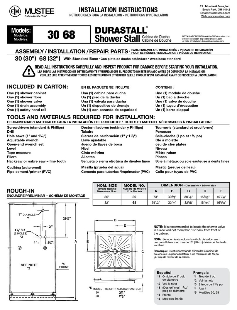
Mustee
Mustee DURASTALL 30 installation instructions

Lakes
Lakes COASTLINE ONE DOOR QUADRANT ENCLOSURE Installation & maintenance
