Aplisens SGE-25.SMART User manual

DTR.SG...04
(ENG)
APLISENS
MANUFACTURE OF PRESSURE TRANSMITTERS
AND CONTROL INSTRUMENTS
USER’S MANUAL
SMART LEVEL PROBES TYPE:
SGE-25.SMART; SGE-25S.SMART
HYDROSTATIC LEVEL PROBES
SGE-25; SGE-25S; SGE-25C; SGE-16.
Edition C
WARSAW JUNE 2010
APLISENS JSC 03-192 Warszawa, ul. Morelowa 7
tel. +48 22 814 07 77; fax +48 22 814 07 78
www.aplisens.pl, e-mail: aplisens@aplisens.pl

Symbols used
BASIC REQUIREMENTS AND SAFE USE
- The manufacturer will not be liable for damage resulting from incorrect installation,
failure to maintain the device in a suitable technical condition, or use of the device other
than for its intended purpose.
- Installation should be carried out by qualified staff having the required authorizations to install
electrical and pressure-measuring devices. The installer is responsible for performing the
installation in accordance with these instructions and with the electromagnetic compatibility and
safety regulations and standards applicable to the type of installation.
- The device should be configured appropriately for the purpose for which it is to be used.
Incorrect configuration may cause erroneous functioning, leading to damage to the device or an
accident.
- If a device is not functioning correctly, disconnect it and send it for repair to the manufacturer or
to a firm authorized by the manufacturer
In order to minimize the risk of malfunction and associated risks to staff, the device is not to be
installed or used in particularly unfavourable conditions, where the following dangers occur:
- possibility of mechanical impacts, excessive shocks and vibration;
- excessive temperature fluctuation, exposure to direct sunlight;
-
condensation of water vapour, dust, icing.
Installation of intrinsic safety versions should be performed with particular care, in accordance with
the regulations and standards applicable to that type of installation.
The technical manual (DTR) contains parameters for the probes which were correct at the time of going to
press. These parameters may be changed.
The manufacturer reserves the right to make changes (not having a negative impact on the operational
and metrological parameters of the products) without updating the contents of the technical manual.
Symbol Description
Warning to proceed strictly in accordance with the information contained in the
documentation in order to ensure the safety and full functionality of the device.
i
Information particularly useful during installation and operation of the device.
Information particularly useful during installation and operation of a type Ex device.
Information on disposal of used equipment

C 1 DTR.SG...04
(ENG)
CONTENTS.
I. APPENDIX EX.03 (SGE–25.SMART, SGE–25S.SMART, SGE–25C.SMART)................................2
II. APPENDIX EX.04 (SGE–25, SGE–25S, SGE–25C).........................................................................4
1. INTRODUCTION..............................................................................................................................6
2. USER MATERIALS..........................................................................................................................6
3. APPLICATIONS OF PROBES.........................................................................................................6
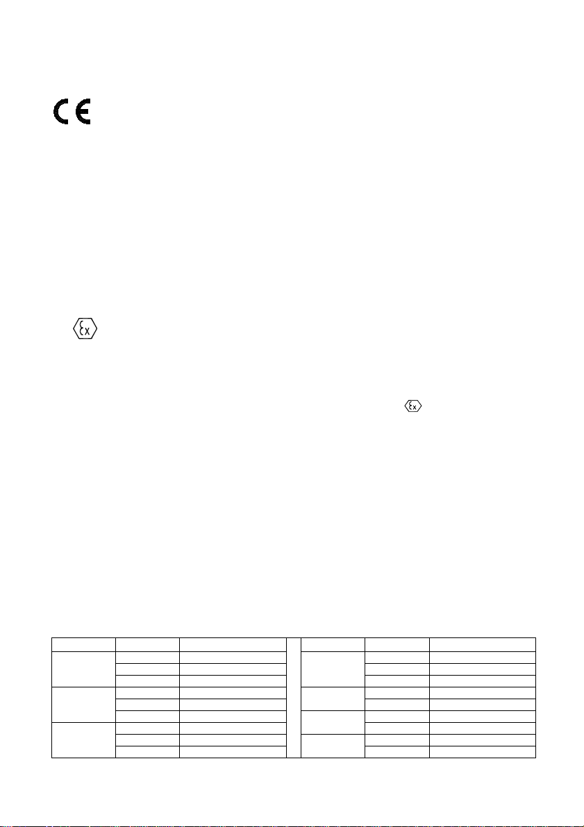
4. IDENTIFYING MARKS. ORDERING PROCEDURE.........................................................................6
5. TECHNICAL DATA..........................................................................................................................6
5.1. T
ECHNICAL DATA
. SGE-25.SMART
AND
SGE-25S.SMART
PROBES
....................................................... 6
5.2. T
ECHNICAL
P
ARAMETERS OF THE
SGE-25 .............................................................................................. 7
5.3. T
ECHNICAL
P
ARAMETERS OF THE
SGE-25S............................................................................................ 8
5.4. T
ECHNICAL
P
ARAMETERS OF THE
SGE-16 .............................................................................................. 8
5.5. T
ECHNICAL
P
ARAMETERS OF THE
SGE-25C............................................................................................ 8
5.6. SGE-25, SGE-16, SGE-25S, SGE-25C. E
LECTRICAL PARAMETERS
........................................................ 8
5.7. C
ONSTRUCTION
M
ATERIALS
: (
FOR WHOLE PROBES
).................................................................................. 9
5.8. I
NGRESS PROTECTION RATING
:............................................................................................................... 9
6. TECHNICAL DESCRIPTION............................................................................................................9
6.1. P
RINCIPLES OF
O
PERATION
.................................................................................................................... 9
6.2. C
ONSTRUCTION
.................................................................................................................................... 9
6.3. E
LECTRONIC CIRCUIT OF THE PROBES
..................................................................................................... 9
7. PLACE OF INSTALLATION...........................................................................................................10
7.2. H
IGH AND
L
OW
A
MBIENT
T
EMPERATURES AND
M
EDIUM
T
EMPERATURES
................................................... 10
8. INSTALLATION AND CONNECTION............................................................................................10
8.1. M
ECHANICAL
I
NSTALLATION
................................................................................................................. 10
8.2. E
LECTRICAL
C
ONNECTION
. .................................................................................................................. 10
9. SETTINGS AND REGULATION.....................................................................................................10
9.1. S
ETTINGS OF
SGE-25, SGE-16, SG-25C
AND
SGE-25S
PROBES
......................................................... 10
9.2. S
ETTINGS OF
SGE-25.SMART, SGE-25S.SMART
PROBES
.................................................................. 10
9.3. SGE-25.SMART, SGE-25S.SMART. M
EASUREMENT RANGES
. D
EFINITIONS
......................................... 10
9.4. C
ONFIGURATION AND
C
ALIBRATION
....................................................................................................... 11
10. INSPECTIONS, REPAIRS AND SPARE PARTS...........................................................................11
10.1. R
EGULAR INSPECTIONS
...................................................................................................................... 11
10.2. A
DDITIONAL
I
NSPECTIONS
.................................................................................................................. 12
10.3. S
PARE
P
ARTS
................................................................................................................................... 13
11. PACKING, STORAGE AND TRANSPORT....................................................................................13
11.1. P
ACKING
, T
RANSPORT
....................................................................................................................... 13
11.2. S
TORAGE
......................................................................................................................................... 13
12. GUARANTEE.................................................................................................................................13
13. ADDITIONAL INFORMATION........................................................................................................13
14. FIGURES .......................................................................................................................................14
F
IGURE
1 SGE-25.SMART
AND
SGE-25S.SMART
PROBES
–
DIMENSIONS
................................................... 14
F
IGURE
2. SGE-25.SMART
AND
SGE-25S.SMART
PROBES
–
CONNECTION METHOD
.................................... 14
F
IGURE
3. SGE-25, SGE-16,SGE-25C
AND
SGE-25S
PROBES
–
DIMENSIONS AND CONNECTION METHOD
....... 15
F
IGURE
4. T
HE PROBE IN
E
X
-
VERSION WITH A CABLE WITH AN
T
EFLON SHIELD
.................................................. 16
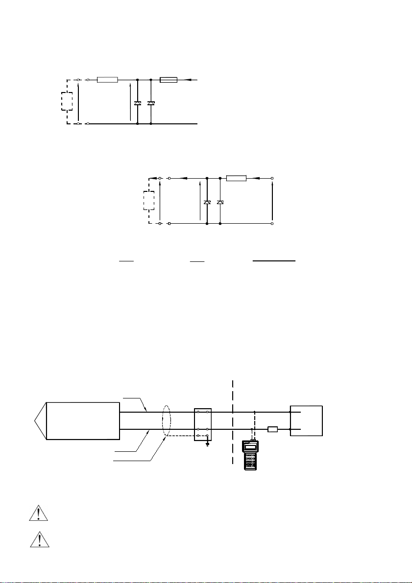
15. APPENDIX 1. TESTING OF EXCESS VOLTAGE PROTECTION ELEMENTS..............................17
F
IGURE
5
A
. T
ESTING THE
T
RANSIL DIODE CONNECTED BETWEEN THE WIRES
.................................................... 17
F
IGURE
5
B
. T
ESTING THE
P
LASMA SURGE ARRESTERS
................................................................................... 17

C 2 DTR.SG...04
(ENG)
I. APPENDIX Ex.03
(SGE–25.SMART, SGE–25S.SMART, SGE–25C.SMART)
DTR.SG...04. Appendix Ex.03
(ENG)
(SGE–25.SMART, SGE–25S.SMART, SGE–25C.SMART)
SMART LEVEL PROBES
type: SGE–25.SMART, SGE–25S.SMART, SGE–25C.SMART
Ex VERSIONS
1. Introduction
1.1 This “Appendix Ex.03” applies only to smart level probes SGE–25.SMART, SGE–25S.SMART,
SGE–25C.SMART in Ex versions, marked on the rating plate as shown in 2.2 and denoted Ex in the
Product Certificate.
1.2 The appendix contains supplementary information relating to the Ex versions of the SGE–25.SMART,
SGE–25S.SMART, SGE–25C.SMART probes. During installation and use of Ex probes reference should
be made to DTR.SG...04 in conjunction with “Appendix Ex.03”.
2. Use of SGE–25.SMART probes in danger zones
2.1. The probes are produced in accordance with the requirements of the following standards:
EN 60079-0:2006, EN 50303:2004, EN 60079-26:2007, EN 60079-11:2007
2.2. The probes may operate in areas where there is a risk of explosion, in accordance with the rating
of the explosion protection design:
II 1G
Ga Ex ia IIC T4/T5/T6
I M1 Ex ia I
KDB 09ATEX008
3. Identifying marks
The above mentioned probes in Ex-version, must have a rating plate containing the information specified in
paragraph 4 of DTR. SG...04, and also at least the following:
- CE mark and number of notified unit: 1453 in the case of GIG KDB, mark
- designation of explosion protection design, certificate number,
- values of parameters such as Ui, Ii, Ci,
-
year of manufacture
4. User information.
Together with the probes ordered, the user will receive: User’s Manual numbered DTR.SG...04 with
Appendix Ex, and also the Product Certificate.
5. Permitted input parameters of the SGE-25.SMART, SGE-25S.SMART,
SGE-25C.SMART probes. (based on data from the KDB 09ATEX008
certificate and certification documentation.)
-permitted input parameters for power supply with a linear characteristic.
Ui = 28V DC Ii = 0,1A
-permitted input parameters for power supply with a “rectangular” characteristic and trapezoidal characteristic
Ui = 24V DC Ii = 0,1A
Input inductance and capacity: Ci = 10nF, Li = 1,0mH
Pi for all type of power supply see table.
Tp = Tm - for Tm > Ta Tm – temperature of measuring medium
Tp = Ta - for Tm < Ta Ta – ambient temperature
1453
Pi[W] Tp[°C] Temperature class Pi[W] Tp[°C] Temperature class
56 T6 61 T6
71 T5 76 T51,5 80 T4, grupa I 1,2 80 T4, grupa I
57 T6 66 T6
72 T5 0,9 80 T5,T4, grupa I1,4 80 T4, grupa I 70 T6
59 T6 0,6 80 T5,T4, grupa I
74 T51,3 80 T4, grupa I

C 3 DTR.SG...04
(ENG)
Appendix Ex.03 (SGE–25.SMART, SGE–25S.SMART, SGE–25C.SMART)
6. Supply examples.
Power supply with a “linear” characteristic may be e.g. a typical barrier with parameters:
Uo=28V Io=0.093A Rw=300
Ω
.
Uo
Rw
I
D
Ui
Fig.1. Power supply from a source with linear characteristic”
Example of power supply from a source with trapezoidal characteristic (see Fig.2).
Uo=24V Io=0,1A
Io
Ui Uo
D
IRw
Uq
Ii
Fig. 2. Power supply from a source with trapezial characteristic
If Uo < ½ Uq then Uq = , Rw = , Po =
For power supply with rectangular characteristic:
Supplementary attentions:
The supply of power from a source with a rectangular characteristic means that the voltage of the
Ex power supply remains constant until current limitation activates.
The protection level of power supplies with a “rectangular” characteristic is normally “ib”.
The probe powered from such a supply is also a Ex device with protection level “ib”.
Example of practical provision of power supply with a rectangular characteristic:
use a stabilized power supply with Uo=24V with protection level „ib” and current limited to 25mA < Io < 30mA
6.1. The protection level
The probe is Ex device with protection level „ia” when the powered circuit have protection level „ia”.
The probe is Ex device with protection level „ib” when the powered circuit have protection level „ib”.
Terminal box
Black
Probe cable
Red
PROBE
_
+
Communicator certified for connection
to a signal line leading to a danger zone.
In the absence of such a certificate,
the transmitter should be configured
and calibrated within a safe zone.
F1 F2 F3 F 4
ABC
1
4
7
STU
JKL
DEF GHI @%&
.
32
VWX
MNO
YZ#
5 6
PQR *
+/
98 0
REPF PV F4
≥250Ω
R
_
+
see p.5 and 6.
a Ex power supply
Hazardous area Safe area
Fig.3. SGE–25.SMART, SGE–25S.SMART, SGE–25C.SMART probes in Ex version – connection method
Devices in the measurement loop of the probe should be connected in accordance with
Intrinsic safety and explosion protection standards.
It is not permitted to repair or otherwise interfere with the probe’s electrical circuits in any way.
Damage and possible repair may be assessed only by the manufacturer or another authorized
party.
probe
Rw ID Example of practical provision of power supply for case:
use the barrier with the parameters given above
probe
Uq
Io
4Po
Ii Uo(Uq-Uo)
Rw`

C 4 DTR.SG...04
(ENG)
II. APPENDIX Ex.04 (SGE–25, SGE–25S, SGE–25C)
DTR.SG...04. Appendix Ex.04
(ENG)
(SGE–25, SGE–25S, SGE–25C)
HYDROSTATIC LEVEL PROBES type: SGE–25, SGE–25S, SGE–25C
Ex VERSIONS
1.
Introduction
1.1 This “Appendix Ex.04” applies only to hydrostatic level probes SGE-25, SGE-25C and SGE-25S in Ex
versions, marked on the rating plate as shown in 2.2 and denoted Ex in the Product Certificate.
1.2 The appendix contains supplementary information relating to the Ex versions of the SGE–25, SGE–25C,
SGE–25S probes. During installation and use of Ex probes reference should be made to DTR.SG...04 in
conjunction with “Appendix Ex.04”.
2. Use of probes in danger zones
2.1. The probes SGE–25, SGE–25S are produced in accordance with the requirements of the following
standards: EN 60079-0:2006, EN 50303:2004, EN 60079-26:2007, EN 60079-11:2007
2.2. The probes may operate in areas where there is a risk of explosion, in accordance with the rating
of the explosion protection design:
II 1G
Ga Ex ia IIC T4/T5/T6
I M1 Ex ia I
KDB 09ATEX007
3. Identifying marks
The above mentioned probes in Ex-version , must have a rating plate containing the information specified in
paragraph 4 of DTR. SG...04, and also at least the following:
- CE mark and number of notified unit: 1453 in the case of GIG KDB, mark
- designation of explosion protection design, certificate number,
- values of parameters such as Ui, Ii, Ci,
-
year of manufacture
4. User information.
Together with the probes ordered, the user will receive: User’s Manual numbered DTR.SG...04
with Appendix Ex.04, and also the Product Certificate.
5. Permitted input parameters of the SGE–25, SGE–25S, SGE–25C probes
(based on data from the KDB 09ATEX007 certificates, and certification
documentation.)
-permitted input parameters for power supply with a linear characteristic.
Ui = 28V DC Ii = 0,1A
-permitted input parameters for power supply with a “rectangular” characteristic and “trapezoidal”
characteristic
Ui = 28V DC Ii = 0,08A
Input inductance and capacity: Ci = 30nF, Li = 750
µ
H
Pi for all type of power supply see table.
Tp = Tm - for Tm > Ta Tm – temperature of measuring medium
Tp = Ta - for Tm < Ta Ta – ambient temperature
1453
Pi[W] Tp[°C] Temperature class Pi[W] Tp[°C] Temperature class
53 T6 60 T6
68 T5 1,3 75 T5, T4, grupa I
1,8 75 T4, grupa I 65 T6
56 T6 1,0 75 T5,T4, grupa I
71 T5 69 T6
1,6 75 T4, grupa I 0,7 75 T5,T4, grupa I

C 5 DTR.SG...04
(ENG)
Appendix Ex.04 (SGE–25, SGE–25S, SGE–25C)
6. Supply examples
Power supply with a linear characteristic may be e.g. a typical barrier with parameters:
Uo=28V Io=0.093A Rw=300
Ω
.
Uo
Rw
I
D
Ui
Fig.1. Power supply from a source with linear characteristic”
Example of power supply from a source with trapezoidal characteristic (see Fig.2).
Uo=28V Io=0,08A
Io
Ui Uo
D
IRw
Uq
Ii
Fig. 2. Power supply from a source with trapezoidal characteristic”
If Uo < ½ Uq then
Uq = , Rw = , Po =
For power supply with rectangular characteristic:
The supply of power from a source with a rectangular characteristic means that the voltage of the Ex power
supply remains constant until current limitation activates.
The protection level of power supplies with a “rectangular” characteristic is normally “ib”.
The probe powered from such a supply is also a Ex device with protection level “ib”.
Example of practical provision of power supply with a “rectangular” characteristic:
– use a stabilized power supply with o Uo=24V with protection level „ib” and current limited to Io=50mA.
6.1. The protection level
The probe is Ex device with protection level „ia” when the powered circuit have protection level „ia”.
The probe is Ex device with protection level „ib” when the powered circuit have protection level „ib”.
Safe areaHazardous area
Terminal box
Black
Probe cable
PROBE
_
+
Red
_
+
a Ex power supply
see p.5 and 6
Fig.3. SGE–25, SGE–25S, SGE–25C probes in Ex version – connection method
Devices in the measurement loop of the probe should be connected in accordance with
Intrinsic safety and explosion protection standards.
It is not permitted to repair or otherwise interfere with the probe’s electrical circuits in any way.
Damage and possible repair may be assessed only by the manufacturer or another authorized
party
Example of practical provision of power supply for case:
use the barrier with the parameters given above
probe
Rw ID
Uq
Io
4Pi
Io Uo(Uq-Uo)
Rw`

C 6 DTR.SG...04
(ENG)
1. INTRODUCTION
1.1. This manual is intended for users of SGE-25.SMART, SGE-25S.SMART, SGE-25, SGE-25S, SGE-25C
and SGE-16 hydrostatic level probes containing the data and guidelines necessary to understand the
functioning of the probes and how to operate them. It includes essential recommendations concerning
installation and use, as well as emergency procedures.
1.2. The SGE-25, SGE-25S and SGE-25SMART, SGE-25S.SMART are also made in Ex version.
Additional data on the probes in Ex version is contained in the appendix designated
„DTR.SG...04
(ENG).
Appendix.Ex.04” or „DTR.SG...04
(ENG
. Appendix.Ex.03”.
During installation and use of the probes in Ex version, reference should be made to DTR.SG...04 in
conjunction with Appendix Ex.
1.3. The level probes: SGE -25, SGE -25S, SGE -25C, SGE -25SMART, SGE -25S.SMART in
realization for sea uses are complied with Det Norske Veritas (DNV) Rules for Classification of Ships,
High Speed & Light Craft and Det Norske Veritas' Offshore Standards. Certificate No. A -11311 for
application in following Location Classes: Temperature C, Humidity: B, Vibrations: B, EMC: B,
Enclosure: D.
2. USER MATERIALS
Probes are delivered in single and/or multiple packs. A probe is delivered together with a “Product Certificate”
which also serves as a guarantee card.
Each batch of probes also carries user’s manual in quantities agreed with the customer
.
3. APPLICATIONS OF PROBES
The SGE-25.SMART, SGE-25S.SMART, SGE-25, SGE-25S, SGE-25C and SGE-16 probes are designed to
measure the depth of liquid in wells, swimming pools, watercourses, boreholes etc.
The SGE-25S.SMART and SGE-25S probes are also designed for the measurement of levels of liquid waste
and of dense or viscous.
The SGE-16 probe, due to its small diameter, is designed fir the measurement of water levels in wells and
boreholes, wherever it is necessary to insert probes into pipes of small diameter for which it is impossible to
use the SGE-25.
The probes convert an input pressure (being a measure of the level of the medium) into a standard 4÷20 mA
signal transmitted in a two-wire system (probes SGE-25, SGE-16, SGE-25C, SGE-25S) and a digital communi-
cation signal in the „HART” system (probes SGE-25.SMART, SGE-25S.SMART),or in special versions into a
0÷10V signal transmitted in a three-wire system (applicable only to the SGE-25, SGE-25S, SGE-25C models).
Probes fitted with cables with an additional Teflon shield may be used with food products and with reactive
substances.
4. IDENTIFYING MARKS. ORDERING PROCEDURE
4.1. Identifying marks on a rating plate
Every probe carries a rating plate containing at least the following information: CE mark, numbers of notified
institutions and designations of certificates obtained, name of manufacturer, type, factory number, basic
range, output signal, power supply voltage.
4.2. Ordering procedure
See the catalogue cards.
5. TECHNICAL DATA
5.1. Technical data. SGE-25.SMART and SGE-25S.SMART probes
5.1.1. SGE-25.SMART, SGE-25S.SMART . Measurement Ranges
Type of probe Basic range
(FSO) Maximum range
(measurement limits) Minimum
set range Ability to shift the
start of the range
Overpressure
limit (without
hysteresis)
0÷10 m H
2
0 -1÷11,5 m H
2
0 0,8 m H
2
0 0÷10 m H
2
0 30 m H
2
0
SGE-25.SMART
SGE-25S.SMART 0÷100 m H
2
0 -5÷115 m H
2
0 8 m H
2
0 0÷100 m H
2
0 300 m H
2
0
i

C 7 DTR.SG...04
(ENG)
5.1.2. SGE-25.SMART . Metrological parameters.
Accuracy ≤± 0,1 % for the basic range
≤± 0,3 % for the minimum set range
Long term stability ≤0,1 % (FSO) for 2 years.
Thermal error < ± 0,08 % (FSO) / 10º C
< ± 0,2 % for the whole thermal compensation range
Thermal compensation range -10 ÷ 80º C
Error due to supply voltage changes 0,002% (FSO) / 1V
5.1.3. SGE-25S.SMART. Metrological parameters.
Accuracy ≤± 0,16 % for the basic range
≤± 0,4 % for the minimum set range
Thermal error < ± 0,08 % (FSO) / 10º C
< ± 0,2 % for the whole thermal compensation range.
Thermal compensation range -10 ÷ 80º C
Error due to supply voltage changes 0,002% (FSO) / 1V
5.1.4. SGE-25.SMART, SGE-25S.SMART. Electrical parameters
Power supply for normal-version 10,5...36 V DC
Power supply for Ex-version see “Appendix Ex.03 SGE–25.SMART, SGE–25S.SMART”
Output signal 4...20 mA or inverse 20...4 mA two wire transmission
Load resistance R[Ω] ≤x 0,85
Communication Communication take place via a 4..20 mA signal using
specialized APLISENS equipment, (see 9).
Resistance required for communication 250...1100 Ω
Minimum supply voltage for Umin.[V] = + 10,5 V
specified load resistance R
L
[
Ω
]
Damping of the sensing module 0,3 s
Damping added electronically 0...30 s
Voltage for insulation testing 500 V AC or 750 V DC
Excess voltage protection see. 10.2.3.
5.1.5. SGE-25.SMART and SGE-25S.SMART . Permitted Environmental Conditions.
Process temperature limit -30...80º C – for the basic range 0...10 m H
2
0
-30...50º C – for the basic range 0...100 m H
2
0
Maximum process temperature for Ex-version see “Appendix Ex.03 SGE–25.SMART,
SGE–25S.SMART”
The medium must not be allowed to freeze in the immediate vicinity of the probe.
5.2. Technical Parameters of the SGE-25
Any measurement range 1...500 m H
2
O for normal version
1...100 m H
2
O for Ex version
Recommended standard ranges 4, 10, 20, 50, 100 m H
2
O
Special version with increased accuracy (SGE-25 level probe, measurement range 0..10 m H
2
O,
accuracy
−
0,1%, Total error at 0...25º C
−
0,3%.)
Hysteresis, repeatability 0,05%
Usup [V] – 10,5 V
0,02 A
R
L
[Ω] x 0,02 A
0,85
Measurement Range
1m H
2
O 4m H
2
O 0...10m H
2
O ÷ 500m H
2
O
Overpressure Limit
(repeatable–without hysteresis) 40 x range 25 x range 10 x range
(max. 700 m H
2
O)
Accuracy 0,6% 0,3 % 0,2 %
Thermal error typical 0,3% / 10º C
max 0,4% / 10º C typical 0,2% / 10º C
max 0,3% / 10º C

C 8 DTR.SG...04
(ENG)
Long term stability 0,1% or 1 cm H2O for 1 year
Thermal compensation range 0 ÷ 25º C – standard,
-10 ÷ 70º C – for special version
Process temperature limit -25 ÷ 50º C – for ranges > 20m H
2
O,
-25 ÷ 75º C – for ranges ≤20m H
2
O,
Maximum process temperature for Ex-version see “Appendix Ex.04 SGE–25, SGE–25S.SMART”.
The medium must not be allowed to freeze in the immediate vicinity of the probe.
5.3. Technical Parameters of the SGE-25S.
Any measurement range 2...20 m H
2
O for normal and Ex-version.
Recommended standard ranges 2, 4, 10 m H
2
O
Hysteresis, repeatability 0,05%
Thermal compensation range 0 ÷ 25º C – standard
Process temperature limit -25 ÷ 75º C
Maximum process temperature for Ex-version see “Appendix Ex.04 SGE–25, SGE–25S.SMART”.
The medium must not be allowed to freeze in the immediate vicinity of the probe.
5.4. Technical Parameters of the SGE-16
Measurement ranges 10; 20; 50; 100m H
2
O
Accuracy 0,5%
Hysteresis, repeatability 0,05%
Overpressure limit (repeatable – without hysteresis) 2 x range
Process temperature limit 0 ÷ 50º C
Thermal compensation range 0 ÷ 25º C
5.5. Technical Parameters of the SGE-25C
Measurement ranges 0...2; 0...4; 0...10 m H
2
O
Accuracy 1%
Hysteresis, repeatability 0,05%
Overpressure limit (repeatable – without hysteresis) 10 x range
Thermal error of zero 0,6% / 10ºC
Thermal error of span 0,4% / 10ºC
Process temperature limit -25 ÷ 75ºC
Thermal compensation range 0 ÷ 25ºC
5.6. SGE-25, SGE-16, SGE-25S, SGE-25C. Electrical parameters
Output signal 4 ÷ 20mA, two wire transmission
Special version (SGE-25, SGE-25S only) 0 ÷10V, three wire transmission, (not applicable toEx-version).
Load resistance R[Ω
]
≤
(for current output)
Load resistance R[Ω]
≥
5kΩ
(for voltage output)
Power supply for normal-version 10,5
÷
36V DC for 4...20mA output
15
÷
30V DC (for 0
÷
10V output)
Power supply for Ex-version see “Appendix Ex.03 SGE–25, SGE–25S”
Error due to supply voltage changes 0,005% / 1V
Measurement Range
2m H
2
O 4m H
2
O 0...10m H
2
O ÷20m H
2
O
Overpressure Limit
(repeatable–without hysteresis) 20 x range 20 x range 10 x range
Accuracy 1,5% 1% 0,5%
Thermal error of zero typical 0,4% / 10º C
max 0,6% / 10º C typical 0,2% / 10º C
max 0,3% / 10º C
Thermal error of span typical 0,3% / 10º C
max 0,4% / 10º C typical 0,2% / 10º C
max 0,3% / 10º C
Usup [V] – 10,5 V
0,02 A

C 9 DTR.SG...04
(ENG)
5.7. Construction Materials: (for whole probes).
Diaphragm: Stainless steel 316L (00H17N14M2)-for SGE-16, SGE-25S, SGE-25S.SMART
Diaphragm: Hastelloy C276 – for SGE-25, SGE-25.SMART, SGE-25C
Sensing module: Stainless steel 316L (00H17N14M2)
Casing for electronic parts: Steel pipe, 316L (00H17N14M2)
Liquid filing the interior of the sensing module: Silicone oil
Cable shield: polyurethane
Additional cable shield: Teflon (fitted by arrangement)
5.8. Ingress protection rating:
SGE-25.SMART, SGE-25S.SMART, SGE-25, SGE-25S, SGE-25C and SGE-16 IP68
6. TECHNICAL DESCRIPTION.
6.1. Principles of Operation
The hydrostatic level probes work by converting changes in the resistance of a piezoresistive bridge, while are
proportional t the pressure (of a hydrostatic column of liquid), into a standard current output signal. The active
sensing device is a silicon diaphragm with in-diffused piezoresistors. The (non-uniformized) electrical signal
obtained from the piezoresistive bridge is proportional to the input pressure (depth) and is converted by the
electronic circuit into an output signal.
6.2. Construction.
6.2.1. The probes are in the shape of a hermetically closed cigar, containing the active sensing device with
silicon and sealing diaphragm, as well as a plate with the electronic components.
The SGE-25S.SMART and SGE-25S probes additionally fitted with a diaphragm seal enabling depth
measurements to be carried out on dense media and media with suspended matter and impurities, such as
liquid waste (fig. 1, 3).
The output signal is passed through a special cable with a capillary used to connect the negative side of the
measuring diaphragm to the atmosphere. All metal parts of the probes are made of 00H17N14M2 stainless
steel (316L), and Hastelloy C276 (see section 5.7.), and the cable has a polyurethane shield.
6.2.2. Special versions of the probes can be produced with cables shielded by an additional teflon layer.
The shield covers the parts of the cable while is immersed in the medium being measured, as well as a
necessary additional segment.
The Teflon shield (in Ex version) is additional equipped in stainless steel cord escorted electrostatic charges
(see fig. 4.).
6.2.3. The probes are fitted with elements ensuring excess voltage protection: „transil” diodes between the
wires, and plasma surge arresters between the wires and the casing.
(The plasma surge arresters not included in Ex versions.)
6.3. Electronic circuit of the probes
Electronic circuit can be produced in two versions:
6.3.1. The digital version (SGE-25.SMART and SGE-25S.SMART probes).
The electronic circuit changes the signal from the sensing module into digital signal and input to a
microprocessor , which controls the probe’s operation. Using data input during the production process, the
processor processes the conversion curve, adjusts for thermal errors and carries out linearization.
After processing, the digital signal is again converted into an analogue 4÷20mA current signal, with a
superimposed digital communication signal.
For communication with the probe via the signal line a special Aplisens communicator KAP is used.
6.3.2. The analog version (SGE-25, SGE-25S, SGE-25C and SGE-16 probes).
The electronic circuit changes the signal from the sensing module into an output signal 4...20 mA.
The electronic circuit is equipped in protective elements assured Intrinsic safety and resistance on electric
impulse.
The electronics board is hermetically flooded hardenable silicone resin in the stainless steel casing.

C 10 DTR.SG...04
(ENG)
7. PLACE OF INSTALLATION
7.1.
The level probes installed in places where liquid levels are measured in wells, swimming pools, tanks,
boreholes etc. The probe is immersed in the medium being measured. A special cable extends above the
level of the medium; this can be connected directly to another device or to a terminal box.
7.2. High and Low Ambient Temperatures and Medium Temperatures.
When measuring liquids whose solidification point is above the ambient temperature, the medium should not
be allowed to freeze around the probe, this applies in particular to water in the case of open-air installations.
For maximum medium temperatures see sect. 5.
Data for versions Ex in accordance with Appendix Ex.03, Appendix Ex.04.
8. INSTALLATION AND CONNECTION
8.1. Mechanical Installation
The probe can be suspended from the power supply cable, but where there is a danger that it may catch on
protruding elements it is recommended that the probe be suspended on a steel cable using the supporting
handle(not applicable to SGE-16). If the cable is to be exposed to current or turbulence, it should be installed
in a protective tube, e.g. one made from PCV.
Directly before location the probe in measured medium to take off from diaphragm seals
SGE-25S, SGE-25S.SMART, SGE-25C the securing cover.
The probe with an additional Teflon shield suspend on a steel cable or on a internal cable (do not catch
for teflon).
The probe in Ex-version with a cord for earthing suspend on a steel cable using the lifting handle
8.2. Electrical Connection.
The method of making electrical connections is shown in figure 2, 3 (for Ex version in figure 3 „Appendix Ex”).
If the transmission line leads to remote premises via the open air, it is recommended that a terminal box, be
fitted, e. g. the Aplisens type PP, in order to connect the probe’s cable to the remaining section of the
transmission line. The box should have an IP65 ingress protection rating, and but should not be so airtight as
to prevent the probe’s active sensing device from “breathing” via a capillary embedded in the cable.
The opening of the capillary should not be allowed to become dirty, and water should not be allowed to enter
the capillary.
Where the transmission line is very long, it is recommended that the section leading from the end of the probe
cable be made from twisted pair cable, and it is desirable that entry points to other devices be fitted with
excess voltage protection, e. g. the Aplisens UZ-2 system.
The cable of the probe and the remaining section of the transmission line should be protected from
mechanical damage.
9. SETTINGS AND REGULATION.
9.1. Settings of SGE-25, SGE-16, SG-25C and SGE-25S probes
The SGE-25, SGE-16, SGE-25C and SGE-25S are factory set to the range stated in the order. The user does
not have access to the “zero” and “range” potentiometers. Setting may be adjusted by the manufacturer only.
9.2. Settings of SGE-25.SMART, SGE-25S.SMART probes
In SGE-25.SMART and SGE-25S.SMART probes with smart electronic, user can make e.g. set „zero” and
measurement ranges.
9.3. SGE-25.SMART, SGE-25S.SMART. Measurement ranges. Definitions.
9.3.1.
The maximum range of level, while the probe can measure is called „basic range” (for specifications
of “ basic range” see 5.1.1.).
The width of the basic range is the difference between the upper and lower limits of the basic range.
The internal characteristic conversion curve for the basic range is coded in the probe’s memory.
This is the reference curve used when making any adjustments which affect the probe’s output signal.
i

C 11 DTR.SG...04
(ENG)
9.3.2.
When the probe is in use the term “set range “ is used.
The set range is the range whose lower end-point corresponds to an output current of 4mA and whose upper
end-point corresponds to a current of 20mA (or 20mA and 4mA respectively when the conversion curve
inverted). The set range may cover the whole of the basic range or only a part of it. The width of the set range
is the difference between the upper and lower limits of the set range. The probe may be set to any range
within the basic range of level values, subject the restrictions set out in the table in 5.1.
1.
9.4. Configuration and Calibration.
9.4.1.
The SGE-25.SMART and SGE-25S.SMART probes has features which enable metrological and
identification parameters to be set and altered. The configurable metrological parameters affecting the probe’s
output signal include the following:
a) unit in which the measured level is expressed on the display
b) upper end-point of the set range
c) lower end-point of the set range
d) time instant
e) type of characteristic curve: linear or radical
Parameters of an informational nature which cannot be altered include the following:
f) upper limit of the basic range
g) lower limit of the basic range
h) minimum set range
9.4.2
. Other identification parameters, not effecting the output signal, include: device address, device code,
factory identification code, factory device code, number of preambles (3÷20), UCS, TSD, program version,
electronics version, flags, factory number, label tag, description tag, date tag, message, record number,
sensing module number.
The process of setting the parameters listed in 9.4.1 and 9.4.2 is called “Configuration”.
9.4.3.
It is possible to adjust the probe’s zero point, for example to compensate for deviation resulting from a
change in position of installation.
The probes may also be calibrated, by taking readings with the input pressure controlled using a standard
device. This process and zero-point adjustment are called “Calibration”.
9.4.4.
Configuration and Calibration of the probe are carried out using an Aplisens KAP communicator,
certain Hart communicators or a PC with Hart/RS232 converter and Aplisens Raport-01 software.
A description of the functions or the KAP communicator is contained in KAP Communicator Operating Manual,
and information on the Hart/RS232 converter can be found on the Hart/RS232/01 Converter information sheet.
A list of Hart protocol commands implemented for SGE-25.SMART, SGE-25S.SMART probes is
contained in the IO.HART operating instructions available at www.aplisens.pl
After configuration it is important to protect the transducers using command HART [247].
During work transmitter should be safe prior to entries. This prevents accidental or intentional
changes configurational data. The protection function is accessible in KAP03 communicator,
“Raport's” software, as well as, in applying DD or DMT programs libraries.
10. INSPECTIONS, REPAIRS AND SPARE PARTS
10.1. Regular inspections.
10.1.1
. Regular inspections should be carried out in accordance with the regulations to which the user
subject
An inspection should be made of the external condition of the probe, during which:
- Check that there are no signs of mechanical damage in the form of impact marks or dents;
- Check the condition of the cable, which should not show signs of wearing, bending or fraying of the
external coating; check the condition of the packing gland.
Every two years or in accordance with regulations applicable to the user, check the zero point (4mA).
i

C 12 DTR.SG...04
(ENG)
10.1.2.
Check the „zero point” (SGE-25, SGE-25S, SGE-25C ) bring the probe up above the surface of the
liquid and read the output current. In case of excessive deviation of the zero reading, return the probe to the
manufacturer for adjustment of the conversion curve or adjust the zero point of a device used in conjunction
with the probe (e.g. monitor, regulator, controller).
10.1.3
. Check the „zero point” SGE-25.SMART, SGE-25S.SMART see 10.1.2.
10.2. Additional Inspections.
If the probe is installed in a place where it might have been subject to mechanical damage, wearing cable
covering, excess pressure, hydraulic impulses, sedimentation, crystallization or erosion of the diaphragm, or
excess electrical voltage, inspections should be made as necessary.
Check the state of the diaphragm and cable, clean the diaphragm, check the zero point
.
10.2.1. Faults in the Transmission Line.
If there is no current in the line or the value of the current is random, check the transmission line, the
connections with the terminal adapters, connectors etc.
If the transmission line is in good order, check whether the probe is functioning correctly.
10.2.2. Effects of Excess Voltage.
In case of a large surge of excess voltage between the wires of the line, the safety diode may sustain damage
due to a low-resistance short circuit (a diode damaged in this way still provides protection to the probe’s
circuits).
Symptoms of damage:
- when the probe is connected to the power supply, the value of the current exceeds 20 mA, and the voltage
on the probe is of an order of several hundred mV (in extreme cases a particularly strong surge may cause
circuits or wires inside the probe to burn out; the current is then 0 mA and there is full voltage in the output
circuit).
- when the probe is not connected to a power supply, the resistance of the probe should be measured; this
is approximately 10
Ω
and is equal to the value of the limiting resistors + resistance of the damaged diode.
Damage to the gas-filled spark gap (Plasma surge arresters) is much less likely than damage to the diode, and
may lead to a short circuit or a lowering of the resistance of the spark gap.
For additional information on how to test the safety devices, see figure. 5a, 5b.
10.2.3. Damage Caused by Overpressure
Another possible reason for malfunctioning of the probe is damage caused by overpressure, which may result
from such factors as
a) freezing of the medium,
b) dynamic effects of a strong current of liquid on the diaphragm seal while the probe is being washed
(applies mainly to the SGE-25S, SGE-25S.SMART model);
c) striking or scraping of the diaphragm with a hard object, such as a screwdriver;
If excess pressure on the probe has caused damage to the silicon or sealing diaphragm, the probe can no
longer be used. Symptoms of such damage are generally such that the output current falls below 4 mA or
rises above 20 mA, and the probe fails to react to input pressure.
10.2.4. Cleaning the Diaphragm Seal
Impurities which have accumulated on the diaphragm during operation should not be removed by mechanical
means such as scraping, scrubbing etc., as this may cause damage. The only permitted method is to dissolve
the impurities, possibly aiding their removal with a light brush.
Sedimentation on the diaphragm may affect the conversion curve.
Examples of ways of cleaning the diaphragms:
a. In the case of boiler scale on and around the diaphragm, the lower part of the probe including the
diaphragm should be immersed for approximately 20 minutes, for example in a 10% solution of Kamix,
which is available from the manufacturer.
b. Deposits of petroleum-derived substances should be softened and rinsed off with a solvent of detergent
c.
Deposits of organic substances or food products (juice, syrup etc.) should be softened in warm water up
to 85˚ C, or in detergent in the case of fats.
After removing sedimentation, parts which have come into contact with the solvent substance
should be thoroughly rinsed, and the health and safety regulations relating to the chemical in
question should be adhered to.
Do not use substances which might cause corrosion of the diaphragm seal.
i

C 13 DTR.SG...04
(ENG)
10.3. Spare Parts.
The following parts of the probe can be replaced when worn or damaged: cable, seals on the packing gland.
The cable may be replaced by the manufacturer only.
11. PACKING, STORAGE AND TRANSPORT
11.1. Packing, Transport.
The probes should be packed in such a way as to protect them from damage during transportation, in single or
multiple packs. The cable should be rolled into a loop
≥
300 mm in diameter, secured so as to prevent the coils
from moving relative to each other and the whole from moving within the package. Avoid breakage to the
cable at the point where it enters the packing gland. Packing should take place in closed rooms, where the air
temperature is not lower than +15°C, relative humidity does not exceed 85%.
Land, sea or air transport may be used, provided that direct action of atmospheric effects is prevented.
11.2. Storage
The probes should be stored in multiple packs in covered rooms, free of vapours and reactive substances,
with an air temperature between +5°C and +40°C and relative humidity not greater than 85%.
12. GUARANTEE.
The manufacturer guarantees the proper functioning of the probes SGE-25.SMART, SGE-25S.SMART,
SGE-25, SGE-16, SGE-25C for a period of 24 months starting from the date of purchase (probe SGE-25S for a
period of 12 months), as well as servicing carried out under the guarantee and following the guarantee period.
13. ADDITIONAL INFORMATION
Related standards:
PN-EN 60529:2003 Ingress protection rating of casing (IP code)
PN-EN61010-1 Safety requirements for automated electrical measuring devices and
laboratory devices. General requirements.

C 14 DTR.SG...04
(ENG)
14.
FIGURES
SGE-25S.SMART probe
+
Black or black/blue wire
SGE-25.SMART probe
152 (SGE-25.SMART)
153 (SGE-25S.SMART)
140
Zero level
Zero level
Special version of probe.
Cable with additional
teflon covering
Supporting handle
Teflon tube
+
_
Capillary 2x0,5
Black or black/blue wire
Red or red/yellow wire
141
14.5
_
+
_
∅
25
∅
25
∅
60
∅
Figure 1 SGE-25.SMART and SGE-25S.SMART probes – dimensions
+
Communicator
_
Power
+
R
(for operation with communicator)
250 < R< 1100 )
ΩΩ
Load resistance
supply
Terminal box PP or UZ-2/N protection system
(when cable length exceeds 100m).
Red
Black
PROBE
Screen
_
Figure 2. SGE-25.SMART and SGE-25S.SMART probes – connection method

C 15 DTR.SG...04
(ENG)
To take off the securing cover
level
Zero
SGE25 and SGE-16 probe
level
Zero
SGE-25C probe
Zero
level
152(SGE-25)
142(SGE-25C)
140(SGE-25)
170(SGE-16)
153(SGE-25S)
182(SGE-16)
130
∅
25
16(SGE-16)
25(SGE-25)
∅
∅
Teflon tube Capillary 2x0,5
Supporting handle
(Not applicable to SGE-16)
∅
directly before location the probe
To take off the securing cover directly before location the probe
60
∅
SGE-25S probe
14.5
141
25
∅
+
-
+
Black or black/blue wire
-
Red or red/yellow wire
-
+
Black or black/blue wire
_
Recommended for all lengths of cable.
Terminal box PP or UZ-2 protection system
(when cable length exceeds 100m).
Connection of SGE-25, SGE-16, SGE-25S and SG-25C in a two-wire system
Terminal box PP or UZ-2 protection system.
Connection of SGE-25, SGE-25S and SGE-25C in a three-wire system (0…10V output signal).
Black
Not applicable to Ex version.
(4…20mA output signal).
PROBE
Screen
Black
_ _
Red
+ +
Screen
+
PROBE
_
0…10V output
Red Blue
measurement system
24 VDC
Power supply/
measurement system
Power supply/
0...10V
+24 VDC
Not applicable to Ex version.
Cable with additional
Special version of probe.
teflon covering
Figure 3. SGE-25, SGE-16,SGE-25C and SGE-25S probes – dimensions and connection method

C 16 DTR.SG...04
(ENG)
L=2m
or by order
on a steel cable using
SGE-25, SGE-25SMART
SGE-25S, SGE-25S.SMART.
the lifting handle.)
Steel band
Lifting handle
Teflon tube
(The probe suspend
Cord for earthing
to mounting of probe)
(do not using
Cord for earthing
Set screw
Set screw
Red "+"
Black"-"
Cable screen
Figure 4. The probe in Ex-version with a cable with an Teflon shield.

C 17 DTR.SG...04
(ENG)
15. APPENDIX 1. Testing of excess voltage protection elements
(Not applicable to Ex version)
__
Probe (not immersed)
+ +
UZ power
supply
set to 50V DC
R
V1
Figure 5a. Testing the Transil diode connected between the wires.
(Not applicable to Ex version)
a) The results for an undamaged diode should be as follows:
R=600Ω, UZ=24VDC - line current 4mA
R=2 kΩ, UZ=50VDC - line current raised by approx. 1.5 mA to 5.5 mA
voltage V1 37 ÷ 41 V
b) Results indicating damage to the diode:
R=600Ω, UZ=24VDC - line current 40mA
voltage V1 ok. 0,5 V
or when resistance is measured on the probe cable – R ≈11 Ω
_
_
V2
Probe
+
V1
R
+
UZ power
up to 250VDC
supply
Figure 5b. Testing the Plasma surge arresters.
(Not applicable to Ex version)
The Plasma surge arresters is working correctly if:
a) The resistance between the shorted wires of the probe and the casing at a test voltage of approx. 50V
is ≥0.5 GΩ.
b) When UZ is increased gradually, the sparking voltage should be approximately 90, 250 V depending on
the type of device (attention should be paid to the value of U2, which at the moment of ignition will fall to
20 V – a reading of U1 taken at this point gives the ignition voltage).
If the protective elements do not pass the above tests, the probe should be returned to the manufacturer
for repair.

Other manuals for SGE-25.SMART
2
This manual suits for next models
5
Table of contents
Other Aplisens Accessories manuals
Popular Accessories manuals by other brands

OtterBox
OtterBox OBFTC-0038-A Safety instructions

Becker
Becker Centronic SunWindSet SWS441-II technical information

Lenovo
Lenovo Active Pen 3 LP-251 Safety, warranty & quick start guide

Gram
Gram K3-F quick start guide

ABB
ABB TOTALFLOW LevelMaster Series Startup guide

TIS
TIS TIS-HEALTH-CM installation manual