Genasun GV-10 User manual

GV-10-Pb-12V: 12V Lead-Acid/AGM/Gel/Sealed/Flooded
GV-10-Pb-CV: 12V Custom Multi-Stage Lead-Acid/AGM/Gel/
Sealed/Flooded
GV-10-Li-12.5V: 11.1V (3s) Lithium Cobalt/Polymer
GV-10-Li-14.2V: 12V (4s) Lithium Iron Phosphate
GV-10-Li-16.7V: 14.8V (4s) Lithium Cobalt/Polymer
GV-10-Li-CV(**.*V): Custom CC/CV or Multi-Stage Lithium Variation
GV-10 Manual
For models:
Solar Charge Controllers with Maximum Power Point Tracking
IMPORTANT SAFETY INSTRUCTIONS | SAVE THESE INSTRUCTIONS
GENASUN GV-10 (ALL MODELS) MANUAL, REVISION 2.0 | 01.2018
10.5A / 140W
www.genasun.com
GENASUN
c/o BLUE SKY ENERGY
2598 FORTUNE WAY • SUITE K
VISTA, CA 92081 • USA
(see specs p.7 for the max. power of Li-ion versions.)

This manual contains important instructions for the GV-10-Pb and GV-10-Li solar charge controllers that shall be followed during
installation and maintenance. Various models of the GV-10 are available to charge dierent battery types as follows:
• GV-10-Pb-12V: 12V Lead-Acid/AGM/Gel/Sealed/Flooded
• GV-10-Pb-CV: 12V Custom Multi-Stage Lead-Acid/AGM/Gel/Sealed/Flooded
• GV-10-Li-12.5V: 11.1V (3s) Lithium Cobalt/Polymer
• GV-10-Li-14.2V: 12V (4s) Lithium Iron Phosphate
• GV-10-Li-16.7V: 14.8V (4s) Lithium Cobalt/Polymer
• GV-10-Li-CV(**.*V): Custom CC/CV or Multi-Stage Lithium Variation
Consult your battery charging specifications to ensure that the GV-10 is compatible with your chosen batteries.
The GV-10 includes a 20A fast-acting ATO fuse rated 32V.
WARNING: EXPLOSION HAZARD. DO NOT REMOVE OR REPLACE FUSES UNLESS POWER HAS BEEN DISCONNECTED OR THE AREA IS
FREE OF IGNITABLE CONCENTRATIONS. DO NOT CONNECT OR DISCONNECT WHEN ENERGIZED. DO NOT DISCONNECT WHILE THE
CIRCUIT IS LIVE OR UNLESS THE AREA IS FREE OF IGNITABLE CONCENTRATIONS.
ATTENTION: RISQUE D'EXPLOSION. NE PAS CONNECTER NI DÉCONNECTER PAS LORSQU'IL EST SOUS TENSION. NE PAS CONNECTER
LE CIRCUIT ALORS QUE EST VIVANT OU A MOINS QUE LA ZONE EST LIBRE DE CONCENTRATIONS IGNITAIRES. NE PAS RETIRER NI
REMPLACER LES FUSIBLES À MOINS QUE LA PUISSANCE A ÉTÉ DÉCONNECTÉE OU QUE LA ZONE N'A PAS DE CONCENTRATIONS
ÉCLAIRÉES.
CAUTION for the GV-10-Pb (Lead Acid Versions Only): INTERNAL TEMPERATURE COMPENSATION. RISK OF FIRE, USE WITHIN 0.3 m (1
ft) of BATTERIES. Lead-acid batteries can create explosive gases. Short circuits can draw thousands of amps from a battery. Carefully
read and follow all instructions supplied with the battery. Use only 12V lead-acid batteries with the GV-10-Pb-12V and GV-10-Pb-CV.
DO NOT SHORT CIRCUIT the solar array when plugged into the controller. DO NOT MEASURE SHORT CIRCUIT CURRENT of the array
while connected to the controller. This may damage the controller, and such damage will not be covered under warranty.
Safety Instructions:

Grounding is not necessary for operation and is at the user's discretion. If the GV-10 is to be used with a solar array electrically
connected to earth ground, please note the following: WARNING: THIS UNIT IS NOT PROVIDED WITH A GFDI DEVICE. Consult Article
690 of the National Electrical Code (or the standards in force at the installation location) to determine whether a GFDI is necessary
for your installation.
WARNING: THIS UNIT IS NOT PROVIDED WITH DISCONNECT DEVICES. Consult Article 690 of the National Electrical Code (or the
standards in force at the installation location) to determine whether disconnect devices are necessary for your installation.
LITHIUM WARNING: Use caution when working with lithium systems. Genasun Li controllers use the CC/CV charging profile indicated
on the controller. CHECK the specifications of the battery pack to ensure that the CV voltage is correct. Further check that the power
supplied by the solar array and Genasun controller is within the battery specified design limits.
LITHIUM BMS WARNING: Genasun recommends using a lithium battery with a Battery Management System capable of disconnecting
the solar charge controller in the event that any cell in the pack is outside of its rated temperature, current, or voltage range. Failure
to do so may result in property damage, injury or death. Genasun highly recommends the use of a BMS with cell balancing. Cell
balancing is mandatory for lithium iron phosphate.
Use only 10-30 AWG (5.0 mm2max) copper conductors suitable for a minimum of 60 degrees C. If operation at high power or at high
ambient temperatures is expected, wire with a higher temperature rating may be necessary.
Recommended terminal block tightening torque: 7 in-lbs, 0.79 Nm.
Inspection & Maintenance
Inspect the controller at least once per year to ensure proper performance.
• Check for animal or insect damage.
• Inspect for corrosion / water damage.
• Inspect the security of all connections.
• Ensure the solar array does not exceed the maximum input voltage.
• Repair and clean as necessary.

D
I
A
G
R
A
M
1
NO JUMPER FOR NON-
FLOODED AND SEALED
BATTERIES.
ADD JUMPER
FOR FLOODED
BATTERIES:
SUPPLIED
JUMPER
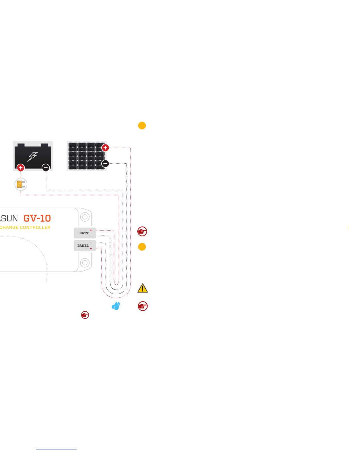
Installation & System Connections:
MOUNTING
Mount the controller near your battery securely using the holes provided on the
enclosure’s flanges or with a means appropriate to the application.
• Mount near the battery (for lead-acid versions only, use within 0.3 m (1 ft) of
batteries. See Caution, p.2).
• The GV-10 can be mounted in any orientation on the floor or wall. We recommend
a position in which all labels are clearly visible.
• Do not expose to water.
• Do not mount in direct sunlight or near a source of heat.
• Allow adequate airflow around the controller to achieve maximum output capability.
• For outdoor use, the controller must be housed in an enclosure providing protection
at least equivalent to NEMA Type 3.
SELECTING THE BATTERY TYPE (LEAD-ACID / PB MODEL ONLY)
Your GV-10-Pb-12V controller is supplied set to the “SEALED” charging profile, which is appropriate for
most types of sealed lead-acid and gel batteries, as well as some types of AGM batteries. A “FLOODED”
setting is available for flooded batteries and other types of AGM batteries. The “FLOODED” setting
includes equalization charging. Please consult the specification table at the end of this manual to
determine the best setting for your battery type. To change your GV-10 controller to the “FLOODED”
setting, unscrew the four screws on the bottom of the controller, remove the top, and install the
supplied jumper on the 6-pin connector as shown in diagram 1. Use care when installing the jumper,
as incorrect installation can damage the controller. For sealed batteries, do not install the jumper.
• Connections should be made according to Article 690 of the National Electrical Code (NFPA 70)
or the standards in force at the installation location.
• Electrical connections may be made in any order; however the sequence below is recommended.
Note*: The positive or negative battery cable must be protected
by a fast-acting fuse or circuit breaker of 20A or less, rated for the
maximum battery voltage and connected close to the battery ter-
minal or power distribution block. This fuse will protect the wiring
in the event of a short circuit or controller damage.
1
2

BATTERY PANEL
Note: Drip loop to protect
charge controller from
water.
CONNECTING THE SOLAR PANEL
Connect the solar panel to the +PANEL and –PANEL terminals. While connecting the battery
first will not damage the GV-10, we recommend connecting the panel first. This eliminates
the risk of short-circuiting the panel while the GV-10 is operating, which can cause damage.
• In most applications, the panel should be connected only to the GV-10.
• Do not use blocking diodes for single-panel installations. The GV-10 prevents reverse-
current flow.
• Multiple panels may be connected in parallel up to the maximum power limit of the
controller, with a blocking diode used for each panel (unless otherwise recommended
by the panel manufacturer). These panels should be the same model and facing the
same direction, otherwise we recommend using a separate controller for each panel.
• Solar panel voltage rises in cold weather. Check that the solar panel open circuit
voltage (Voc) will remain below the maximum input voltage of the GV-10 at the coldest
possible expected temperature.
Note: In the GV-10, the negative side of the battery is connected internally to the
negative side of the solar panel.
CONNECTING THE BATTERY
Connect the battery to the +BATT and –BATT terminals.
• A small spark while connecting the battery is ok.
• Any loads should be connected directly to the battery. The GV-10 does not provide
protection against over-discharge.
The GV-10 has a
MULTICOLOR LED.
Learn about this indicator
on the following page.
CAUTION, RISK OF FIRE OR EXPLOSION: Do not make the final battery connection near
lead-acid batteries that have recently been charging.
*FUSE
4
3
Note: Voltages above 25V applied to the battery terminals will immediately destroy
the GV-10. We recommend wiring the controller directly to the battery through its own
circuit, and not through any battery switch or selector. Do not share wiring between
the GV-10 and an alternator.

LED RUN/CHARGE INDICATION
Standby: The battery is connected properly and ready to charge
when solar panel power is available.
2 SEC. BETWEEN GREEN BLINKS
Charging (low current, less than ~3.7A):
FAST & SHORT GREEN BLINKS
Charging (high current, more than ~3.7A):
LONGER, SLOWER GREEN BLINKS
Charging (current limit): charging at current limit (10.5A+).
LONG, THEN SHORT GREEN BLINKS
Battery Charged: The battery is in the absorption
or float charging stage.
SOLID GREEN LED
LED ERROR INDICATION
Overheat: The controller’s internal temperature is too high.
SETS OF 2 RED BLINKS.
Overload: This could be caused by changing the solar
panel connections while the controller is operating.
SETS OF 3 RED BLINKS.
Battery voltage too low: The controller cannot begin
charging due to low battery voltage. If the nominal battery
voltage is correct (12V), charge the battery by some other
means before use.
SETS OF 4 RED BLINKS
Battery voltage too high: If the nominal battery voltage is
correct (12V), check the functioning of other chargers that
may be connected to the system.
SETS OF 5 RED BLINKS.
Panel voltage too high: Only 12V nominal solar panels may
be used with this controller.
SETS OF 6 RED BLINKS.
Internal Error: Contact your dealer for assistance.
2 LONG BLINKS, FOLLOWED BY ANY NUMBER
OF SHORT BLINKS.
The GV-10 has a MULTICOLOR LED
Status Indication:

Troubleshooting
If the LED Indicator will not light, or displays an indication not listed in this manual:
• Verify correct battery polarity;
• Check that there is a solid electrical connection to the battery;
• Check that battery voltage appears on the GV-10 battery terminal screws;
• Check the GV-10 terminal area for evidence of water or mechanical damage.
The GV-10 will not operate without a battery. If the system appears to be overcharging or the GV-10 will not begin charging, ensure that the solar panel
is wired only to the GV-10. If the GV-10 does not appear to be charging, note that the GV-10 waits up to one minute before trying to restart if is has shut
down due to lack of power from the solar panel. If the LED indicator will not light with a battery connected, or blinks the over-battery-voltage error, or
the controller does not charge, the internal fuse may be blown. Check the fuse inside the GV-10 by removing the four screws on the bottom of the en-
closure. If the fuse is blown, replace it with a 20A fast-acting ATO or ATC fuse rated 32V or higher. For more in-depth system troubleshooting, please
visit the support area of our website: www.genasun.com/support/
Specifications: GV-10-Li-**.*VGV-10-Pb-12V
Maximum Recommended Panel Power: 140W
GV-10-Li-12.5V 120W
GV-10-Li-14.2V 140W
GV-10-Li-16.7V 160W
Rated Battery (Output) Current: 10.5A 10.5A
Nominal Battery Voltage: 12V N/A
Maximum Input Voltage: 34V 34V
Recommended Max Panel Voc at STC: 27V 27V
Minimum Battery Voltage for Operation: 8.5V 8.5V
Input Voltage Range: 0-34V 0-34V
Maximum Input Short Circuit Current*: 10.5A 10.5A
Maximum Input Current**: 19A 19A
*Panel Isc. Maximum input power and maximum input voltage requirements must also be respected. **Maximum current that the controller could draw from an unlimited
source.
Note: The most common causes of blown fuses are:
• Connecting the GV-10 to the battery backwards;
• Shorting the solar panel input while the GV-10 is charging;
• Disconnecting the vehicle's battery while an alternator is running;
• Connecting the GV-10 battery terminals to a 24V battery.
In the latter three cases, there may be other internal damage to the
controller.

Specifications (cont.):
Battery Temperature Compensation: 28mV/°C –
Operating Temperature: -40°C – 85°C -40°C – 85°C
Charge Profile: Multi-Stage with Temperature Compensation CC-CV
Charging Voltages: FLOODED Setting SEALED Setting
Equalization Voltage: 15.0V – –
Equalization Time: 2 Hours – –
Equalization Interval: 30 Days – –
Bulk Voltage: 14.6V 14.3V –
Absorption Voltage: 14.4V 14.1V –
Absorption Time: 2.5 Hours –
Float Voltage (Pb models) or CV Voltage (Li
models): 13.5V 13.7V
GV-10-Li-12.5V 12.5V
GV-10-Li-14.2V 14.2V
GV-10-Li-16.7V 16.7V
Electrical Efficiency: 96% - 98% typical
Tracking Efficiency: 99+% typical
MPPT Tracking Speed: 15Hz
Night Consumption: 0.9mA (900uA)
Environmental Protection: IP40, Nickel-Plated Brass & Stainless Hardware
Connection: 4-position terminal block for 10-30AWG wire
Weight: 6.5oz., 185g
Dimensions: 5.5x2.5x1.2”, 14x6.5x3.1cm
Warranty: 5 years
GV-10-Li-**.*VGV-10-Pb-12V
Copyright © 2018 Genasun. All rights reserved. Changes are periodically made to the information herein which will be incorporated in revised editions of this publication. Genasun may make changes or
improvements to the product(s) described in this publication at any time and without notice.
Certifications:
Other manuals for GV-10
2
This manual suits for next models
5
Table of contents
Other Genasun Inverter manuals
Popular Inverter manuals by other brands

Mase
Mase SILENT 5001DM Maintenance manual

Outback
Outback GTFX2012E installation manual

World Friendship
World Friendship WF-600T Series user manual

Grape Solar
Grape Solar GS-540-KIT-BT installation guide

GreenWorks Pro
GreenWorks Pro IV60A00 owner's manual

IMO Precision Controls
IMO Precision Controls Jaguar VXS user guide