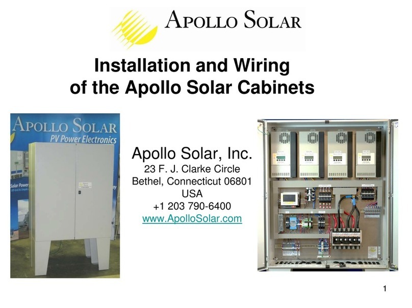
Apollo Solar 3224 User manual

- 0 -
True Sine Wave Inverter / Charger
TSW Series:
3224 / 4048
User’s Manual

- 1 -
TABLE OF CONTENTS
Purpose …………………………………………………………………………………… 3
Scope ……………………………………………………………………………………… 3
Audience ………………………………………………………………………………… 3
Conventions Used ……………………………………………………………………… 3
Important Safety Instructions ………………………………………………………… 4
General Precautions ………………………………………………………………… 4
Personal Precautions ………………………………………………………………… 5
1. Introduction ………………………………………………………………………… 6
1.1 Introduction to the Inverter …………………………………………………...… 6
1.2 Indicators and Settings ………………………………………………….……… 7
2. The Battery Charger ……………………………………………………….……… 8
2.1 Theory of Operation …………………………………………………………….. 8
2.2 Transfer Relay ……………………………………………………………………. 8
2.2.1 Current Rating …………………………………………………………………………………….. 8
2.2.2 Transfer Speed …………………………………………………………………… 8
3. Installation ……………………………………………………………………………. 9
3.1 Installation Steps ………………………………………………………………….. 9
3.11 Selecting a Proper Location ……………………………………………………………………….. 9
3.12 Inverter Mounting (vertical) ……………………………………………………………………….. .. 10
3.13 Inverter Mounting (horizontal) ………………………………………………………………………. 10
4. Wiring …………………………………………………………………………………… 11
4.1 Battery Information ………………………………………………………………... 12
4.1.1 Battery Size …………………………………………………………………………………………. 12
4.1.2 Battery Bank Sizing ………………………………………………… …………………………….. 12
4.1.3 Monthly Maintenance ……………………………………………………………………………… 12
4.1.4 Battery Hook-up Configurations ……………………………………….. ……………………….. 13
4.1.4.1 Parallel Connection …………………………………………………………………………. 13
4.1.4.2 Series Connection …………………………………………………………………………... 13
4.1.4.3 Series-Parallel Connection ………………………………………………………………… 13
4.1.5 Battery Installation ………………………………………………………………………………... 14
4.1.5.1 Battery Location ……………………………………………………………………………. 14
4.1.5.2 Battery Enclosure …………………………………………………………………………… 14
4.1.5.3 Battery Cabling ……………………………………………………………………………… 14
4.2 Grounding ………………………………………………………………………... 15
4.2.1 System Grounding ………………………………………………………………………………. 15

- 2 -
4.2.2 Equipment or Chassis Grounds ……………………………………………………………… 15
4.2.3 Ground Electrodes / Ground Rods ………………………………………………………….. 15
4.2.4 Bonding the Grounding System to the Neutral and Negative Conductors ……. …………. 15
4.3 AC and DC Wiring ……………………………………………………………… 17
4.3.1 DC Wiring ……………………………………………………………………………………….. 19
4.3.1.1 DC Cable Connections ………………………………………………………………….. 20
4.3.1.2 Wiring the Battery Bank ………………………………………………………………… 20
4.3.1.3 Battery Temperature Sensor Installation ……………………………………………… 21
4.3.1.4 Wiring the Inverter to the Battery Bank ……………………………………………….. 21
4.3.2 AC Wiring ……………………………………………………………………………………… 23
4.3.2.1 AC Wire Size and Overcurrent Protection …………………………………………… 24
4.3.2.2 AC Input and Output Wiring Connections …………………………………………… 24
4.4 Apollo TSW Inverter Stacking ……………………………………………….. 25
4.4.1 Connection Diagram …………………………………………………………………………. 25
4.4.2 Parameter Setting ……………………………………………………………………………. 26
4.4.3 Parallel Operation ……………………………………………………………………………. 26
5. Operation ……………………………………………………………………….. 27
5.1 Functional Test and Initial Setup ………………………………………… .. 27
5.2 LCD Screen Descriptions ……………………………………………………………….. 27
5.2.1 Startup Screen ………………………………………………………………………………. 27
5.2.2 Initial Status Screen ……………………………………………………………………….. 27
5.2.3 Inverter Mode Main Status Screen ………………………………………………………. 27
5.2.4 Charger Mode Main Status Screen ………………………………………………………. 28
5.2.5 Search Mode ……………………………………………………………………………….. 28
5.2.6 Error Messages ……………………………………………………………………………... 28
5.3 System Default Settings …………………………………………………………………. 29
6. Technical Specification ………………………………………………………. 30
7. Troubleshooting ………………………………………………………………. 31
8. Service and Support ………………………………………………………….. 31
Five Year Limited Warranty Information ……………………………………….. 32

- 3 -
Purpose
The purpose of this Installation and Operation Manual is to provide explanations and procedures for
installing, operating, maintaining, and troubleshooting TSW series of Inverter/charger.
Scope
The Manual provides safety guidelines, detailed planning and setup information, procedures for installing
the inverter, as well as information for operating and troubleshooting the unit. It does not provide details or
suggestions on specific brands of batteries – consult individual battery manufacturers for this information.
Audience
This manual is intended for anyone who needs to install and operate the TSW inverter/charger. Installers
should be certified electricians or technicians.
Conventions Used
WARNING
Warnings identify conditions or practices that could result in personal injury or loss of life.
Les avertissements identifient les conditions ou les pratiques qui pourraient avoir comme conséquence le
dommage corporel ou les pertes humaines.
CAUTION
Cautions identify conditions or practices that could result in damage to the unit or other equipment.
Les attentions identifient les conditions ou les pratiques qui pourraient avoir comme conséquence les
dommages à l'unité ou à tout autre équipement.
IMPORTANT
These notes describe things that are important to know, but not as serious as a caution or warning.
Ces notes décrivent les choses il est importante savoir que, mais pas aussi sérieux qu'une attention ou un
avertissement.
Abbreviations and Acronyms
AC Alternating Current PV Photovoltaic
ASNET Apollo Solar Network Interface PVGFI PV Ground Fault Interrupter
COM COMmunications Port RE Renewable Energy
DC Direct Current RMA Return Material Authorization
LED Light Emitting Diode TSW Inverter TSW series Inverter/charger

- 4 -
IMPORTANT SAFETY INSTRUCTIONS
INSTRUCTIONS DE SÉCURITÉS IMPORTANTES
SAVE THESE INSTRUCTIONS
CONSERVER CES INSTRUCTIONS
General Precautions
1. Before using the TSW inverter, please read all instructions and cautionary marks on (1) the inverter, (2)
the batteries, and (3) all appropriate sections of this instruction manual.
2. Do not expose INVERTER to rain, snow, or liquids of any type. The INVERTER is designed for indoor
mounting only. Protect the inverter from splashing if used in vehicle applications.
3. Do not disassemble the INVERTER; take it to a qualified service center when service or maintenance
is required. Incorrect re-assembly may result in risk of electric shock or fire.
4. To reduce risk of electric shock, disconnect all wiring before making any attempt to maintain or clean.
Simply turning off the INVERTER will not reduce this risk.
WARNING
5. WORKING IN THE VICINITY OF A LEAD ACID BATTERY IS DANGEROUS. BATTERIES
GENERATE EXPLOSIVE GASES DURING NORMAL OPERATION. Provide ventilation to outdoors
from the battery compartment. The battery enclosure should be designed to prevent accumulation and
concentration of hydrogen "pockets" at the top of the compartment. Vent the battery compartment from
the highest point. A sloped lid can also be used to direct the flow through the vent opening location.
ATTENTION:
Une batterie peut présenter un risque de choc électrique, de brûlure par transfert d’énergie, d’incenie ou
d’explosion des gaz dégagés. Suivre les précautions qui s’imposent.
6. NEVER charge a frozen battery.
7. No terminals or lugs are required for hook-up of the AC wiring. AC wiring must be no less than
10 AWG (5.3mm
2
) gauge copper wire and rated for 90º
ºº
ºC or higher. Crimped and sealed copper
ring terminal lugs with a 5/16 inch hole should be used to connect the battery cables to the DC
terminals of the INVERTER. Soldered cable lugs are also acceptable .See section on battery cable
sizing for more details for your application (see Table 4.1 page 18).
8. Torque all AC wiring connections to 30 in-lbs (3.4 N-m). Torque all DC cable connections to 5 ft-lbs
(6.78 N-m). Be extra cautious when working with metal tools on or around batteries. The potential of
dropping a tool causing the batteries or other electrical parts resulting in sparks could cause an
explosion. Tools required for AC wiring connections: wire strippers, 1/2"(13mm) open-end wrench or
socket, Phillips screw driver #2, slotted screw driver 3/16"(4.6 mm) blade.
9. The INVERTER must be used with a battery supply of nominal voltage that matches the last two digits
of the model number; e.g., 24 volts with a TSW3224, and 48 volts with a TSW4048.
10. GROUNDING INSTRUCTIONS. This battery charger should be connected to a grounded, permanent
wiring system. For most installations, the negative battery conductor should be bonded to the
grounding system at one, and only one, point in the system. All installations should comply with all
national and local codes and ordinances.

- 5 -
11. Personal Precautions
1.Someone should be within voice range when you work near batteries in case of an emergency.
2.Have plenty of fresh water and soap nearby in case battery acid contacts skin, clothing, or eyes.
3.Wear complete eye and clothing protection. Avoid touching eyes while working near batteries.
Wash your hands when done.
4.If battery acid contacts skin or clothing, immediately wash with soap. If acid enters eyes
immediately, flood eyes with cool, running water for at least 15 minutes. Immediately seek medical
attention.
5.Never smoke or allow a spark or flame in the vicinity of a battery or generator.
6.Be extra cautious when working with metal tools on and around batteries. The potential of dropping
a tool causing the batteries or other electrical parts resulting in sparks could cause an explosion.
7.Remove personal metal items such as rings, bracelets, necklaces, and watches when working with
a battery. A battery can produce a short -circuit current, which is high enough to weld a ring or the
like to metal causing severe burns.
8.If a remote or automatic generator starter system is used to disable the automatic starting circuit
and/or disconnect the generator from its starting battery while servicing to prevent accidental
starting during servicing.

- 6 -
1. Introduction
1.1 Introduction to the Inverter
The TSW series inverter is not only an inverter but also contains a powerful intelligent charger.
Actually, it contains three modules in a single unit: inverter, charger and switch.
The TSW series inverter is a heavy-duty, continuous working module generating a sinusoidal wave
from a 24V, or 48V battery bank, which can supply energy to various loads such as resistive load
(heater), inductive load (air conditioners, refrigerator), motors (vacuum cleaners), and rectifier load
(computer). All TSW series are designed to work in heavy load condition. De-rating is not necessary.
It provides a rapid and complete charging process.
The TSW series are True Sine wave Inverters, not to be confused with Modified Sine wave models on
the market. Unlike the modified sine wave counterpart, a true sine wave inverter provides a pure
signal which will not interfere with some of the sensitive electronic equipment currently on the market.
The TSW series inverters provide a 120/240 Volt AC Split-Phase input and output. No external
transformers are required for step up, step down or balancing, thus saving added costs, installation
time, and several points of efficiency. The output provides 240 volts for well pumps, appliances, or
shop tools while providing 120 volts for standard circuits. Either side of the output line can supply up
to 75% of the total load. The input can accept the line or 240 volt AC generators. The transfer relay
is internal.
The smart charger can be set with different charging profiles and battery capacities to match in
various battery types and sizes. The switch module automatically diverts the energy transfer path
between inverter and utility source. When the utility source is lower than the transfer level, the path
switches to the inverter. Otherwise the load is conducted to the utility source. The transfer time is
1/4~1/2 of the total cycle time. The high power charger (100A) can charge a 24V/1000 AH battery
bank in 10 hours. For example, a single unit of Inverter TSW 3224 with a 1000 AH battery bank can
supply a 3200W workload for over 6 hours after a charge of 10 hours.
TSW series is an extremely good choice for utility back up power. However, it also can be used as a
UPS for computers.

- 7 -
1.2 Indicators and Settings
Figure 1.0: TSW Control Panel
Display: This is a 16 character by 2 line LCD which provides operational information and setup prompts.
Note: For detailed description of the LCD screens, refer to the Operation Section 5.0.
On LED: Glows green to indicate that the inverter is powered on (i.e. connected to the battery and receiving
power).
Status LED: Glows amber to indicate the following functions:
Page Key: Allows the user to scroll through the various LCD screens (refer to Operation Section for
description of individual screen data.
Standby Key: Allows the user to enter/exit standby mode.
Audible Indication: Provides a loud audio tone to signal mode change or error conditions.

- 8 -
2. The Battery Charger
2.1 Theory of Operation
The internal battery charger and automatic transfer relay allow the unit to operate as either a battery
charger or inverter, but not at the same time. An external source of AC power (e.g. line power or
generator) must be supplied to the Inverter’s AC input in order to allow it to operate as a battery
charger. When the unit is operating as a charger, AC loads are powered by the external source (i.e.,
generator or public power).
The Battery Charger utilizes a five stage charger algorithm (Bulk, Absorb, Float, Equalize and
Standby). Figure 2.0 is a chart which illustrates the operation of this unit.
Figure 2.0: Battery Charger operation
2.2 Transfer Relay
2.2.1 Current Rating
40 Amps per leg
2.2.2 Transfer Speed
The transfer time is 1/4~1/2cycle (8ms max).
APOLLO SOLAR T80 TurboCharger tm
BATTERY CHARGING DETAILS
13
14
10
0
10
20
30
40
50
60
70
80
BATTERY VOLTAGECHARGING CURRENT
12
11
15
BULK CHARGE MODE
(CONSTANT CURRENT)
(Approx 80% of energy s replaced
n the bulk mode.)
ABSORB MODE
(CONSTANT
VOLTAGE)
FLOAT
MODE
STANDBY
Inverter On
ABSORB SET POINT
FLOAT SET POINT
MAX CHARGE CURRENT SET POINT
2 HOURS
A
B
E
F
START
D
C

- 9 -
3.0 Installation
3.1 Installation Steps
3.1.1 Selecting appropriate Location
The Inverter is a sophisticated electronic device and should be treated accordingly. When selecting
the operating environment for the inverter, do not think of it in the same terms as other equipment that
works with it (e.g. Batteries, diesel generators, motor generators, washing machines, etc). It is a
highly complex microprocessor controlled device. It should be treated similarly to other electronic
devices (e.g. entertainment equipment, computers, etc.) The use of conformal coated circuit boards,
plated copper bus bars, powder coated metal components, and stainless steel fasteners allows the
unit to function in hostile environments, but high humidity/varying temperature (condensing)
environment should be avoided. In a condensing environment the life expectancy of the inverter
cannot be determined and the warranty is voided.
CAUTION
It is in your best interest to install the Inverter in a dry protected location away from sources of high
temperature and moisture. Exposure to saltwater is particularly destructive and potentially
hazardous.
ATTENTION
Il est dans votre meilleur intérêt d'installer l'inverseur dans un endroit protégé sec à partir des sources
de température et d'humidité. L'exposition à l'eau de mer est particulièrement destructive et
potentiellement dangereuse.
Locate the Inverter as close as possible to the batteries in order to keep the battery cables short.
However, do not locate the inverter in the same compartment as non-sealed batteries. The Inverter
may be located in a compartment with other sealed electronic equipment. Batteries generate
hydrogen and oxygen. If accumulated, this combination could be ignited by an arc resulting from
connection of the battery cables or by switching a relay.
Do not mount the inverter in a closed container. Unrestricted airflow is required to operate at high
power for sustained periods of time. Without it, the protection circuitry will activate and reduce the
maximum power available.

- 10 -
3.1.2 Inverter Mounting (Vertical)
The TSW Series inverter may be mounted vertically or horizontally. The vertical
configuration is preferable when using the Apollo Solar Switch Gear. Apollo
Switch Gear provides a convenient method for mounting other Balance of
System (BOS) components such as circuit breakers, shunts, etc.
The next section shows dimensions which will aid in mounting the unit. Be sure
to mount on a strong stable surface (some suggestions follow). The next section
details horizontal mounting of the TSW series Inverter.
Please Note, the TSW Series inverter is shipped with the Display/Keypad
mounted for the vertical mounting configuration. To position it for
horizontal mounting, please follow the steps below:
•
Remove the four (4) Display/Keypad mounting screws
•
Carefully rotate the Display/Keypad 90 degrees
•
Re-install the mounting screws using care not to over tighten.
Horizontal mounting is necessary when using the TSW Series Inverter as a replacement for other
inverters with a similar form factor.
3.1.3 Inverter Mounting (Horizontal)
It is recommended that the TSW Inverter be mounted on a ¾” plywood sheet which is nailed or
screwed into the wall studs. Ensure that the plywood spans across three wall studs for adequate
support. Alternately, when mounting horizontal, two 2x4s may be placed 8” on center to mount the
inverter. Again, be sure to span three studs for adequate support.
It is best to locate the Inverter approximately 4 – 5 feet from the floor.

- 11 -
4. Wiring
+BUS
-BUS
AC BREAKERS
CHASSIS
EARTH
GND
APOLLO SOLAR
BATTERY
TEMPERATURE
SENSOR
BATTERY BOX AND BATTERIES
(MADE BY OTHERS)
BATTERY MAY BE 24 OR 48V
DEPENDING ON THE INVERTER.
(24 VOLT VERSION SHOWN)
STRINGS MAY BE TIED IN
PARALLEL FOR MORE AMP-HRS.
WIRED FOR 120/240VAC SPLIT PHASE
6V
BATT
6V
BATT
6V
BATT
6V
BATT
BATTERY
VOLTAGE
SENSE
WIRES
PV IN
240VAC
IN FROM
LINE OR
GENERATOR
240VAC
OUT TO
LOAD
PANEL
DC IN
APOLLO SOLAR
TS 3224
TRUE SINE AVE
INVERTER / CHARGER
APOLLO SOLAR
TS 3224 or TS 4048
TRUE SINE AVE
INVERTER/CHARGER
APOLLO SOLAR T80
PV CHARGE
CONTROLLER
125V DC
BREAKERS
APOLLO
SHUNT
BOARD
GND
BATTERY PV
ARRAY
AC OUT AC IN
ASNET
CAT-5
ETHERNET
CABLE
INTERNET
OPTIONAL
REMOTE DISPLAY
APOLLO
COMMUNICATION
GATEWAY
ACG-1
PV
IN
BAT
OUT
TurboCharger
Solar Power Center
PV INPUT
(UP TO 75A)
WIRES MAY BE AS
LARGE AS AWG #2
AWG #3
PV
IN
250
GFP
* GND NOTE: IF THIS SYSTEM IS THE SOURCE OF THE
BUILDING POWER, THE AC NEUTRAL MUST BE
CONNECTED TO EARTH GROUND AT THIS POINT ONLY.
IF THE SYSTEM HAS AN AC INPUT AT A CIRCUIT
BREAKER BOX, THE AC NEUTRAL MUST BE TIED TO
GROUND AT THAT SOURCE OF POWER ONLY.
AC
AC
NOTE: AC
NEUTRAL AND
DC NEGATIVE
WIRES ARE
WHITE, BUT ARE
SHOWN AS
LIGHT GRAY.
Figure 4.0: Typical system wiring diagram (single inverter).

- 12 -
4.1 Battery Information
4.1.1 Battery Size
Batteries are the Inverter’s fuel tank. The larger the batteries the longer the INVERTER can operate
before recharging is necessary. An undersized battery bank results in reduced battery life and
disappointing system performance.
Avoid discharging batteries to more than 50% of their capacity too often. Under extreme conditions,
such as a severe storm or a long utility outage, cycling to a discharge level of 80% is acceptable.
Totally discharging a battery may result in permanent damage and reduced life.
For stand-alone applications, battery size should provide between 3 and 5 days of storage before
needing to be recharged. The power contribution from other charging sources is not included in this
calculation to duplicate the conditions present during a cloudy or windless period. This is often
referred to as the "number of days of autonomy." If the system is a hybrid system with daily generator
runs periods then the battery size may be smaller. During cloudy periods the generator would be
expected to run longer. Utilities back up applications often have very small batteries. The minimum
recommended battery capacity is 100 amp-hours@24vdc, and 50 amp-hours@48vdc.
4.1.2 Battery Bank Sizing
To determine the proper battery bank size, compute the number of amp hours that will be used during
charging cycles. Doubling the expected amp hour usage ensures that the batteries will not be overly
discharged and extends battery life. To compute total amp hours usage, determine the amp hour
requirements of each load and total them.
You can compute your battery requirements using the nameplate rating of your appliances. The
formula is WATTS=VOLTS X AMPS. Divide the wattage of your load by the battery voltage to
determine the amperage the load will draw from the batteries.
If the AC current is known, then the battery amperage will be as follows:
AC Current x AC Voltage / Battery Voltage = DC amps.
Multiply the amperage by the number of hours that the load will operate, and you have a reasonable
estimate of amp hours.
Motors are normally marked with their running current rather than their starting current. Starting
current may be three to six times running current. Manufacturer's literature may provide more
accurate information than the motor nameplate. For larger motors, increasing the battery size
indicates that the high demand for start-ups should be required.
Follow this procedure for each individual load. Add the resulting amp hour requirements for each load
to arrive at a total requirement. The minimum properly sized battery bank should be approximately
double this amount. This will allow the battery to be cycled only 50% on a regular basis.
4.1.3 Monthly Maintenance
The level of the electrolyte of a flooded battery should be checked monthly. It should be about 1/ 2"
above the top of the plates, but not completely full. Don't overfill the batteries or the electrolyte will
seep out during charging. Refill the batteries with distilled water. Avoid "spring" water and regular tap
water as they may have high mineral levels that can affect the battery chemistry and reduce life.
Check the battery interconnections for tightness and corrosion. If corrosion is found, disconnect the
cables; clean them with a mild solution of baking soda and water. DO NOT ALLOW THE SOLUTION
TO ENTER THE BATTERY. Rinse the top of the battery with clean water when finished (replace the
caps first.)

- 13 -
To reduce corrosion on the battery terminals, coat them with a thin layer of petroleum jelly or
anti-corrosion grease available from automotive parts stores or battery suppliers. Do not apply any
material between the terminal and the cable lugs, the connection should be metal to metal. Apply the
protective material after the bolts have been tightened
4.1.4 Battery Hook-up Configurations
Battery banks of substantial size can be configured by connecting several smaller batteries. There
are three ways: parallel, series, or series-parallel.
4.1.4.1 Parallel Connection
Batteries are connected in parallel when all of the positive terminals and all of the negative terminals
of a group of batteries are connected. In a parallel configuration the battery bank has the same
voltage as a single battery and an amp/hour rating equal to the sum of the individual batteries. This is
done when the battery voltage matches the inverter voltage.
4.1.4.2 Series Connection
When batteries are connected with the positive terminal of one to the negative terminal of the next,
they are connected in series. In a series configuration the battery bank has the same amp/hour rating
as a single battery and an overall voltage equal to the sum of the individual batteries. This is common
with 24 volt or higher battery-inverter systems.
4.1.4.3 Series-Parallel Connection
As the name implies, both of the above techniques are used in combination. The result is an increase
in both the voltage and the capacity of the total battery bank. This is done very often to make a larger,
higher voltage battery bank out of several smaller, lower voltage batteries. This is common with all
battery-inverter system voltages.

- 14 -
4.1.5 Battery Installation
CAUTION
Batteries can produce extremely high currents in short-circuit. Be very careful working around them.
Read the important safety instructions at the beginning of this manual and the battery supplier's
precautions before installing the Inverter and batteries.
ATTENTION
Les batteries peuvent produire les courants extrêmement élevés dans le court-circuit. Soyez
fonctionnement très soigneux autour de elles. Lisez les instructions de sûreté importantes au début
de ce manuel et de la batterie supplier' ; précautions de s avant d'installer l'inverseur et les batteries.
4.1.5.1 Battery Location
Batteries should be located in an accessible location with nothing restricting access to the battery
caps and terminals. At least two feet of clearance above is recommended. Locate as close as
possible to the Inverter, but do not limit access to the Inverter and the Inverter's disconnect. Do not
locate the inverter in the same compartment with non-sealed batteries (sealed batteries are
acceptable) as the gasses produced during charging are very corrosive and will shorten the life of the
inverter.
Battery to inverter cabling should be no longer than required. For 24 VDC systems do not exceed 10
feet (one way) if 4/0 AWG cables are used. For 48 VDC systems do not exceed 20 feet (one way) if
4/0 AWG cables are used.
4.1.5.2 Battery Enclosure
Batteries should be protected within a ventilated, locked enclosure or room. The enclosure should be
ventilated to the outdoors from the highest point to prevent accumulation of hydrogen gasses that are
released from the battery during charging. An air intake should also be provided at a low point in the
enclosure to allow air to enter to promote good ventilation. For most systems a one-inch diameter
vent pipe from the top of the enclosure is adequate. A sloped top can help direct the hydrogen to the
vent location and prevent pockets of hydrogen from occurring. The enclosure should also be capable
of containing at least one battery cell worth of electrolyte in the event a spill or leak occurs. The
enclosure should be made of acid resistant material or have an acid resistant finish. If the batteries
are located outdoors, the enclosure should be rainproof and have mesh screens over any openings
to prevent insects and rodents from entering. Before placing the batteries in the enclosure, cover the
bottom with a layer of baking soda to neutralize any acid that might be spilled in the future.
4.1.5.3 Battery Cabling
Heavy cables should be used to connect individual batteries to configure a larger battery
bank. The actual size of the cable depends upon whether the batteries are connected in parallel or
series. Generally, the cables should not be smaller than the main battery cables to the inverter. E.g.
If the main cables are 4/0 AWG the battery interconnects should be 4/0 AWG.
It is preferable to connect the batteries first in series and then in parallel when connecting smaller
batteries. The best option is to connect the batteries both in series and parallel in a configuration
often called "cross-trying'. This requires additional cables but reduces imbalances in the battery and
can improve the overall performance. Consult your battery supplier for more information regarding
the hook-up configuration required for your system.

- 15 -
4.2 Grounding
4.2.1 System Grounding
System grounding is often the most misunderstood wiring concept. The subject is more easily
discussed if it is divided into three separate subjects. The grounding requirements vary widely by
locale and application. Consult local codes and the NEC (ANSI/NFPA 70) for specific requirements.
4.2.2 Equipment or Chassis Grounds
This is the simplest part of grounding. This involves connecting the metallic chassis of the various
enclosures to have them at the same voltage level. This reduces the potential for electric shock. It
also provides a path for fault currents to flow resulting in blown fuses or tripped circuit breakers. The
size of the connecting conductors should be coordinated with the size of the over current devices
involved. Under some circumstances the conduit and enclosures themselves will provide the current
paths.
4.2.3 Ground Electrodes / Ground Rods
There are two purposes of the grounding electrode, also known as a ground rod. The first is to
"bleed" off any electrical charge that may accumulate in the electrical system. The second is to
provide a path for 'induced electromagnetic energy' or lightning to be dissipated. The size of the
conductor to the grounding electrode or grounding system is usually based on the size of the largest
conductor in the system. Most systems use a 5/8' (16mm) copper plated rod 6 feet (2meters) long
driven in to the earth as a grounding electrode. It is also common to use copper wire placed in the
concrete foundation of the building as a grounding system. While either method may be acceptable,
the local code will prevail. Connection to the ground electrode should be done with special clamps
located above ground where they can be periodically inspected.
Well casings and water pipes may be used as grounding electrodes. Under no circumstance should
a gas pipe or line be used. Consult local codes and the NEC (ANSI/NFPA 70) for more information.
4.2.4 Bonding the Grounding System to the Neutral and Negative Conductors
This is the most confusing part of grounding. The purpose is to connect one of the current carrying
conductors, usually the AC neutral and DC negative, to the grounding system. This connection is
why we call one of the wires "neutral" in North American electrical systems. You can touch this wire
and the grounding system and not receive a shock. When the other ungrounded conductor, the hot
or positive, touches the grounding system, current will flow through it to the point of connection to the
grounded conductor and back to the source. This will cause the over current protection to shop the
flow of current, protecting the system. The point of connection between the grounding system and
the current carrying conductor is often called a "bond." It is usually located in the over current
protection devices' enclosure. Although the point of connection can be done at the inverter, codes do
not generally allow it since the inverter is considered a "serviceable” item which may be removed from
the system. In residential systems the point of connection is located at the service entrance panel.
In some countries the neutral is not bonded to the grounding system. This means you may not know
when a fault has occurred since the over current device will not trip unless a "double" fault occurs.
This type of system is used in some marine electrical codes.
Bonding must be done at only one point in an electrical system. Our systems inherently have two
separate electric systems- a DC system and an AC system. This means that two bonding points will
occur in all inverter applications. The bonding point will also be connected to the chassis ground
conductors. It is common to have two separate conductors connect the ground electrode and the two
bonding points. Each conductor should use a separate clamp.

- 16 -
Figure 4.1: Recommended system grounding
DC SYSTEM
CHASSIS GROUND
AC SYSTEM
APOLLO SOLAR TSW INVERTER
NEUTRAL
GROUNDING
ELECTRODE
CONDUCTOR GROUNDING
ELECTRODE
NEUTRAL
BUS-BAR
HOT IN
DC NEGATIVE
BUS-BAR
TO
BATTERY
GROUND
BUS-BAR
SYSTEM
BONDING
JUMPERS
EQUIPMENT
GROUND
CONDUCTOR
HOT OUT
HOT IN
HOT OUT
NEUTRAL
AC TRANSFER
SWITCHAND
FILTERBOARD
CHASSIS GROUND
DC
APOLLO SOLAR TSW
INVERTER
GROUNDING DETAILS
AC

- 17 -
4.3 AC and DC Wiring
Figure 4.2: TSW Inverter with AC and DC wiring including essential circuit breakers utilizing Solar
Switchgear
TM
. The CHASSIS GND bus bar is the central ground point. Please note DC Ground
connection (repositioned for clarity).
+BUS
-BUS
AC BREAKERS
CHASSIS
EARTH
GND
APOLLO SOLAR
BATTERY
TEMPERATURE
SENSOR
BATTERY BOX AND BATTERIES
(MADE BY OTHERS)
BATTERY MAY BE 24 OR 48V
DEPENDING ON THE INVERTER.
(24 VOLT VERSION SHOWN)
STRINGS MAY BE TIED IN
PARALLEL FOR MORE AMP-HRS.
WIRED FOR 120/240VAC SPLIT PHASE
6V
BATT
6V
BATT
6V
BATT
6V
BATT
BATTERY
VOLTAGE
SENSE
WIRES
PV IN
240VAC
IN FROM
LINE OR
GENERATOR
240VAC
OUT TO
LOAD
PANEL
DC IN
APOLLO SOLAR
TS 3224
TRUE SINE AVE
INVERTER / CHARGER
APOLLO SOLAR
TS 3224 or TS 4048
TRUE SINE AVE
INVERTER/CHARGER
APOLLO SOLAR T80HV
PV CHARGE
CONTROLLER
125V DC
BREAKERS
APOLLO
SHUNT
BOARD
GND
BATTERY PV
ARRAY
AC OUT AC IN
ASNET
CAT-5
ETHERNET
CABLE
INTERNET
OPTIONAL
REMOTE DISPLAY
APOLLO
COMMUNICATION
GATEWAY
ACG-1
PV
IN
BAT
OUT
TurboCharger
Solar Power Center
PV INPUT
(UP TO 75A)
WIRES MAY BE AS
LARGE AS AWG #2
AWG #3
AWG #3
APOLLO SOLAR
S ITCHGEAR
MODULE
ENCLOSURE
PV
IN
250
GFP
* GND NOTE: IF THIS POWER CENTER IS THE SOURCE
OF THE BUILDING POWER, THE AC NEUTRAL MUST BE
CONNECTED TO EARTH GROUND AT THIS POINT ONLY.
IF THE SYSTEM HAS AN AC INPUT AT A CIRCUIT
BREAKER BOX, THE AC NEUTRAL MUST BE TIED TO
GROUND AT THAT SOURCE OF POWER ONLY.
AC
AC
NOTE: AC NEUTRAL AND
DC NEGATIVE WIRES ARE
WHITE, BUT ARE SHOWN
AS LIGHT GRAY.

- 18 -
GND
500A SHUNT
IN LINE 0.5 A
FUSE
4/0 GAUGE WIRE 250A DC
BREAKER
AC NEUTRAL BUS
GROUND BUS
40A MAX AWG #8
BYPASS
40A
40A
40A
40A
40A
40A
*GND
NOTE
AWG #6
250A DC
BREAKER
NEUTRAL
L2
NEUTRAL
L1
AC NEUTRAL BUS
GROUND BUS
AC IN
AC OUT
40A MAX AWG #8
L2
L1
BYPASS
40A
40A
40A
40A
40A
40A
AWG #6
OPTIONAL DELTA
302R LIGHTNING
ARRESTORS
50A
50A
45A
45A
RES
.5A
45A
45A
Figure 4.3: A pair of TSW Inverters in complete system with Charge Controller from Photovoltaic input.
Refer to section 4.3.4 for additional information on Stacking Inverters.
Please note: DC grounds repositioned for clarity.
APOLLO DC INPUT AC INPUT WIRING AC OUTPUT WIRING
MODEL Amps AWG mm2 120 VAC 240 VAC 120 VAC 240 VAC
TSW3224 160A 2/0 AWG 67 40A 8 AWG 40A 8 AWG 40A 8 AWG 40A 8 AWG
TSW4048 90A 1/0 AWG 50 40A 8 AWG 40A 8 AWG 40A 8 AWG 40A 8 AWG
Table 4.1 Input/Output Ampacity and Minimum Recommended Wire Gage

- 19 -
4.3.1 DC Wiring
WARNING
Even though DC Voltage is low voltage, significant hazards may exist, particularly from short
circuits of the battery system. A 250A rated circuit breaker must be used on the DC input.
AVERTISSEMENT
Quoique la tension CC Soit basse tension, les risques significatifs peuvent exister, en particulier
des courts-circuits de l'installation de batterie.
CAUTION
The inverter is NOT reverse polarity protected. Use care not to connect the negative and
positive battery voltage backward or damage to the inverter will result. Verify the correct voltage
polarity before connecting the DC wires.
ATTENTION
L'inverseur n'est pas polarité renversée protégée. Prenez soin de ne pas relier le négatif et la
tension positive de batterie vers l'arrière ou les dommages à l'inverseur résultera. Vérifiez la
polarité correcte de tension avant de relier les fils de C.C.
IMPORTANT
DO NOT connect the battery cables to the inverter until all wiring is complete and the correct
voltages and polarities are verified.
IMPORTANT
Ne reliez pas les câbles de batterie à l'inverseur jusqu'à ce que tout le câblage soit complet et les
tensions et les polarités correctes sont vérifiées.
THIS IS THE SYMBOL FOR GROUND:
GND
Figure 4.4: Terminals (DC Side) – Positive Top Left, Negative Bottom Right, Ground Lug Bottom Right
•When the inverter is installed in a Photovoltaic system, the NEC (ANSI/NFPA 70)
GROUND LUG
This manual suits for next models
3
Table of contents
Other Apollo Solar Inverter manuals
Popular Inverter manuals by other brands

Helvi
Helvi COMPACT 306HF instruction manual

Katana
Katana S610M user manual

TECO
TECO A510-2001-H instruction manual

Kayden
Kayden WVC Series user manual

Triarchy Technologies
Triarchy Technologies VSG6G1C operating manual

Champion Global Power Equipment
Champion Global Power Equipment 200964 Operator's manual