manuals.online logo
Brands
  1. Home
  2. •
  3. Brands
  4. •
  5. APP
  6. •
  7. Cables And Connectors
  8. •
  9. APP SPEC Pak User manual

APP SPEC Pak User manual

SPEC Pak® High Power Plug
Assembly Instructions For 2, 3 & 6 Position
Step 1 Slide PG Gland assembly onto wires
• Pull approximately 14 inches (355 mm) of wire through the gland to allow working space.
Step 2 Cable and/or Wire Preparation
• Jacketed cable: Strip outer jacket. Strip insulation from discrete wires (See Table 1
& Figure 2)
• Discrete wires: Strip insulation from discrete wires (See Table 1 & Figure 2)
Caution: Do not damage copper conductors when stripping wires
Table 1
Step 3 Secure body of PG Gland to Receptacle Shell
• Apply a generous bead of Permabond 941 or Loktite 411 to the center of the gland
thread and rotate the gland body to insure full coverage. Work quickly. The adhesive
sets quickly.
• Hand tighten body of PG Gland to the Plug Shell until snug, tighten 1/8 - 1/4
turn with spanner or crescent wrench
Caution: Do NOT over tighten the sealing gland body to the shell. Do NOT tighten
the sealing nut at this time.
Step 4 Contact Termination
• Insert wire into crimp barrel to the full depth
• Visually verify that all strands are inserted into the barrel
• Follow the appropriate crimp instructions which are included with the crimp tools
and/or at www.andersonpower.com
Caution: Keep all Powerpole®contacts parallel to each other while crimping jacketed
cable. Improper crimping my produce high resistance or contact distortion.
Plug Shell Holder Set #8 x 5/8 Screw Gland Assembly
Included Component Included Component Included Component Optional Component
Tool PN Tool Type Contact Series Contact
1309G4 Hand PP75 5900, 5952 or 5915
1368 Die-less Hydraulic PP120 1319, 1319G4, 1319G6, 1323G1, 1323G2
1368 Die-less Hydraulic PP180 1328G1, 1328G2, 1347, 1348, 1382, 1383, 1384
PM1000G1 Hand Auxiliary PM16P12S30, PM16P1416S30, PM16P1620S30,
(PowerMod®) PM16P2024S30, PM16S12S32, PM16S1416S32,
PM16S1620S32 or PM16S2024S32
You will need: - Wire Stripping Tool - APP Crimp Tool, See Section 2 - Phillips Head Screw Driver - 8 Screws, Size #10 or M5
Power Contact
Signal Contacts
SPEC Pak®High Power Shell Kit:
X
PG Gland Sealing Nut
Figure 1
Figure 2
Figure 3
Figure 4
For additional tools see data sheet
or www.andersonpower.com.
Powerpole®Contacts
Outer Jacket – 4” [102 mm]
Contact
Series
PP75 9/16” (14.5 mm)
PP120 15/16” (24.0 mm)
PP180 1-1/8” (28.6 mm)
“X”
PowerMod®Signal Contacts
Outer Jacket – 5.5” [139.7 mm]
Wire Insulation Wire Insulation
Contact OD < Barrel ID OD < Barrel ID
Pins 0.18” (4.5 mm) 0.24” (6.0 mm)
Sockets 0.21” (5.5 mm) 0.28” (7.0mm)
HEADQUARTERS: Anderson Power Products®, 13 Pratts Junction Road, Sterling, MA 01564-2305 USA T:978-422-3600 F:978-422-0128 • EUROPE: Anderson Power Products® Ltd., Unit 3, Europa
Court, Europa Boulevard, Westbrook, Warrington, Cheshire, WA5 7TN United Kingdom T: +44 (0) 1925 428390 F: +44 (0) 1925 520203 • ASIA / PACIFIC: IDEAL Anderson Asia Pacic Ltd., Unit 922-928
Topsail Plaza, 11 On Sum Street, Shatin N.T., Hong Kong T:+(852) 2636 0836 F:+(852) 2635 9036 • CHINA: IDEAL Anderson Technologies (Shenzhen) Ltd., Block A8 Tantou Western Industrial Park,
Songgang Baoan District, Shenzhen, PR. China 518105 T: +(86) 755 2768 2118 F: +(86) 755 2768 2218 • TAIWAN: IDEAL Anderson Asia Pacic Ltd., Taiwan Branch, 4F.-2, No.116, Dadun 20th St., Situn
District, Taichung City 407, Taiwan (R.O.C.) T: +(886) 4 2310 6451 F:+(886) 4 2310 6460 • www.andersonpower.com
SPEC Pak® High Power Plug
Page 2
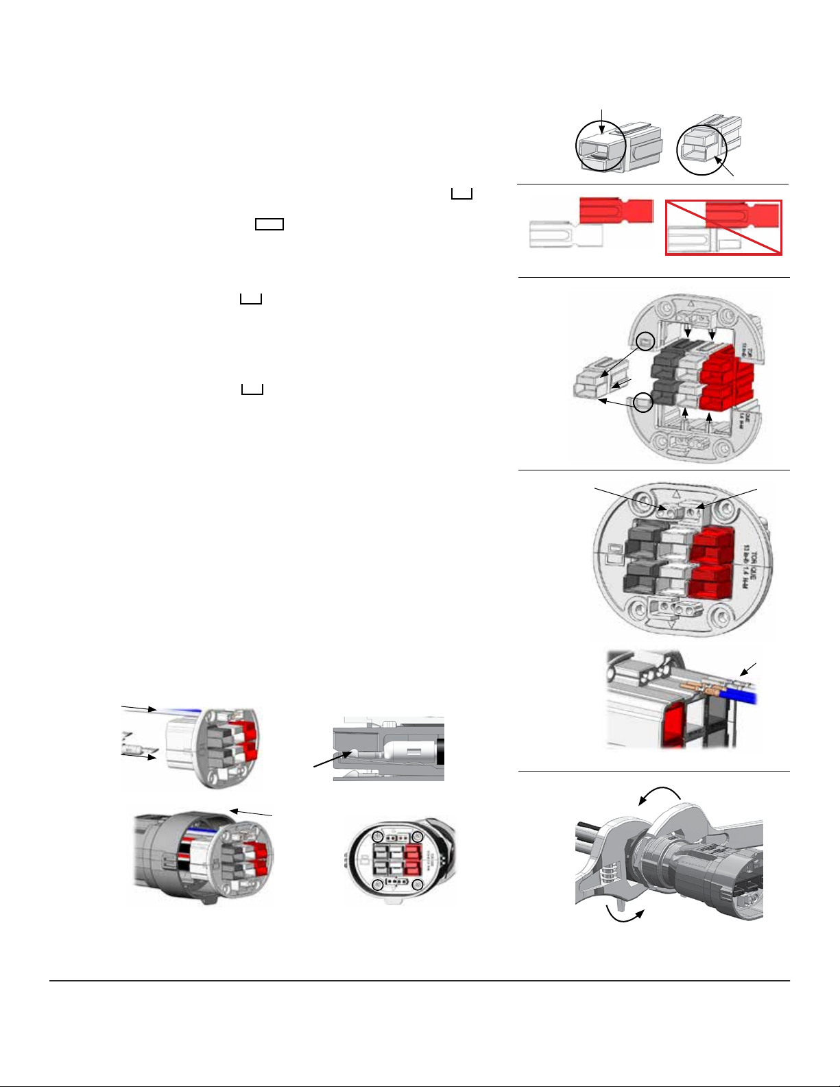
Step 5 Block Powerpole®housing together
• Orient Powerpole®housings with hoods down (See Figure 4)
• Block Powerpole®housings by interlocking dove tails to create individual rows (See Figure 5)
• If more than one row is required, block rows together by interlocking dove tails
Step 6 Insert Powerpole®block into Powerpole®Holder
• With Hood down, slide Powerpole®block into the holder half marked with on
the left side, aligning the holder posts with the grove in Powerpole® (See Figure 6)
• Orient the remaining holder half with on the left side (See Figure 6)
• Slide remaining half into the assembly, inserting the holder posts into the Powerpole®
grove and aligning the tongues and grooves on the holder halves
Step 7 Install Crimped Signal Contacts into the Connector Housings:
• Orient the insert holder with the to the left
• Snap the crimped signal contacts into the appropriate holes in the back of the holder
halves (See Figure 7). A tactile snap will be felt when contact is latched.
• Repeat until all signal contacts have been installed into the housing
Step 8 Install Crimped Power Contacts into the Connector Housings
• Orient the insert holder with the to the left
• Insert crimped power contacts into the appropriate Powerpole®housing until the
contact lip snaps over the edge of the spring (See Figure 8)
• Repeat until all power contacts have been installed
Step 9 Install insert holder into the plug shell
• Prior to inserting the holder into the plug shell, create 2” (50.8 mm) of slack in
the signal wires, if applicable. Hint: To maintain the proper amount of slack with the
wires, temporarily tape wires together.
• Secure insert holder to the plug by tightening the screws in an alternating manner.
Torque: 13 in-lb (1.4 N-M) (See Figure 9)
Step 10 Secure Sealing Nut on Gland
• Hand tighten until snug.
• Stabilizing sealing gland body (from step 3) with a spanner or crescent wrench
(see Figure 10).
• Tighten additional ½ - ¾ turn using a second spanner or crescent wrench.
Caution: Do NOT over tighten the sealing gland body to the shell.
All Data Subject To Change Without Notice
“SPEC Pak, Powerpole, Anderson Power Products, APP & A, are registered trademarks of Anderson Power Products” 15661 1S6558 REV 02
Figure 4
Figure 5
Figure 6
Figure 7
Figure 10
Correct
Incorrect
PinsSockets
Signal Pin & Socket
Hood Up
Hood Down
Suggest Hood
Orientation for Plug
Grove
Figure 9
Figure 8

Other APP Cables And Connectors manuals

APP SPEC Pak User manual

APP

APP SPEC Pak User manual

APP SPEC Pak User manual

APP

APP SPEC Pak User manual

APP SBS50 User manual

APP

APP SBS50 User manual

APP Extreme Power SPEC Pak User manual

APP

APP Extreme Power SPEC Pak User manual

APP SBX 175 Series User manual

APP

APP SBX 175 Series User manual

Popular Cables And Connectors manuals by other brands

Weh TW54 operating instructions

Weh

Weh TW54 operating instructions

Lenze L-force EYF A Series Mounting instructions

Lenze

Lenze L-force EYF A Series Mounting instructions

ELEQ LS-84 installation guide

ELEQ

ELEQ LS-84 installation guide

EIS ZiLOG ZUSBOPTSC01ZACG manual

EIS

EIS ZiLOG ZUSBOPTSC01ZACG manual

HELGI HI0312-V2.0 user manual

HELGI

HELGI HI0312-V2.0 user manual

Sven Base HDMI High Speed user manual

Sven

Sven Base HDMI High Speed user manual

Philips SDW5062O Specifications

Philips

Philips SDW5062O Specifications

Marechal Electric MELTRIC CS1000 operating instructions

Marechal Electric

Marechal Electric MELTRIC CS1000 operating instructions

Gomax SP-5008P3 user manual

Gomax

Gomax SP-5008P3 user manual

Xo NB-Q233A user manual

Xo

Xo NB-Q233A user manual

FasTest FI Series user manual

FasTest

FasTest FI Series user manual

Rolls MS20c owner's manual

Rolls

Rolls MS20c owner's manual

LEGRAND WIREMOLD MDSF installation instructions

LEGRAND

LEGRAND WIREMOLD MDSF installation instructions

Fluke DSX-PLA-004-RKIT installation guide

Fluke

Fluke DSX-PLA-004-RKIT installation guide

StarTech.com 35BAYPANEL installation manual

StarTech.com

StarTech.com 35BAYPANEL installation manual

National Instruments NI SHC68 user guide

National Instruments

National Instruments NI SHC68 user guide

Rosewill RCW-605. user manual

Rosewill

Rosewill RCW-605. user manual

CMR versius manual

CMR

CMR versius manual

manuals.online logo
manuals.online logoBrands
  • About & Mission
  • Contact us
  • Privacy Policy
  • Terms and Conditions

Copyright 2025 Manuals.Online. All Rights Reserved.