Appleton • 1.800.621.1506 • www.appletonelec.com 303359 Rev. D 05/13 • Page 4 of 12
Installation
!WARNING
Electrical power must be turned OFF before and during installation and maintenance. Failure to do so may result in serious or fatal
injuries due to electrocution.
!CAUTION
Before starting the installation, ensure the receptacle assembly is suitable for the intended location according to the National Electrical
Code or Canadian Electrical Code. If the receptacle assembly is not suitable, serious damage and injuries may result. Owners are
responsible for damages or injuries if these rules are not followed.
Prepare the Mounting Position
1. The receptacle assembly must be mounted on four 13/32 inch or 3/8 inch steel, hex head bolts per ANSI B18.6.3 and securely
fastened to a wall, column, strut, or other vertical structure, in one plane, which is capable of supporting the receptacle and its
associated conduit and wiring.
NOTE: Bolts are not provided with the receptacle assembly.
2. Prepare the structure for mounting bolts by drilling, tapping, using securing nuts, or another method of providing thread anchors for
the bolts. See Figure 1 for the dimensions of the receptacle.
3. The bolts must be engaged at least ve full threads.
Mounting the Receptacle
!WARNING
Before mounting the receptacle, ensure that the enclosed switch is in the “OFF” condition.
1. Place the receptacle assembly on the previously prepared mounting bolts, with the receptacle ip cover at the lower-most position.
Make sure that the bolt shanks are in the mounting holes. Tighten the bolts to 18 to 20 ft.- lb. torque.
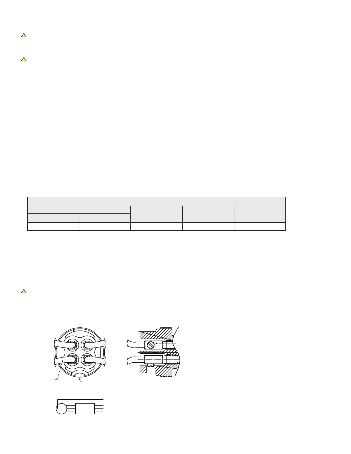
Opening the Receptacle Cover
1. Referring to Figure 2, turn the cover locking screw (Item #3) clockwise (inwards) until it enters into the groove of the receptacle
housing body (Item #4). This makes the enclosure cover (Item #2) free for rotation and simultaneously locks the receptacle interior
rotation (also toggling of the switch).
2. Turn the enclosure cover counterclockwise (outward) to completely remove it from the enclosure.
3. After removal, we recommend that the enclosure cover be placed with the outer surface down, on a clean surface. Protect the
enclosure cover with a tarp or covering to ensure that it remains clean and functional.
Conduit Installation
!CAUTION
Please note that all conduit entries must be used. Install sealing ttings within 18 inches of each conduit entry per the National Electrical
Code requirements.
1. Conduit entries of 2 inch NPT are provided on both the top and bottom of the enclosure (see Figure 1).
2. Make sure all conduit entries are clean and free of debris before installing the conduit and close-up plugs.
3. On all conduits, reducer bushings, and close-up plugs, grease must be used to completely seal out water.
NOTE: We recommend applying Appleton thread lubricant (part number TLC-3) on threads in three generous lines, running parallel
to the thread axis and spaced equidistant around the thread.
4. Conduits and close-up plugs must be turned in until snug and then 1/2 turn further with a wrench. Make sure any installed
breathers and drains are tightened in the same manner.
NOTE: Do not over-tighten, as damage to the housing threads or any reducer bushings may occur.
5. At this point, ensure that all threaded holes in the housing are closed (including openings for breathers and drains) to prevent entry
of rain, splashed water, and hose directed water, and also to comply with Class I and Class II hazardous location requirements.