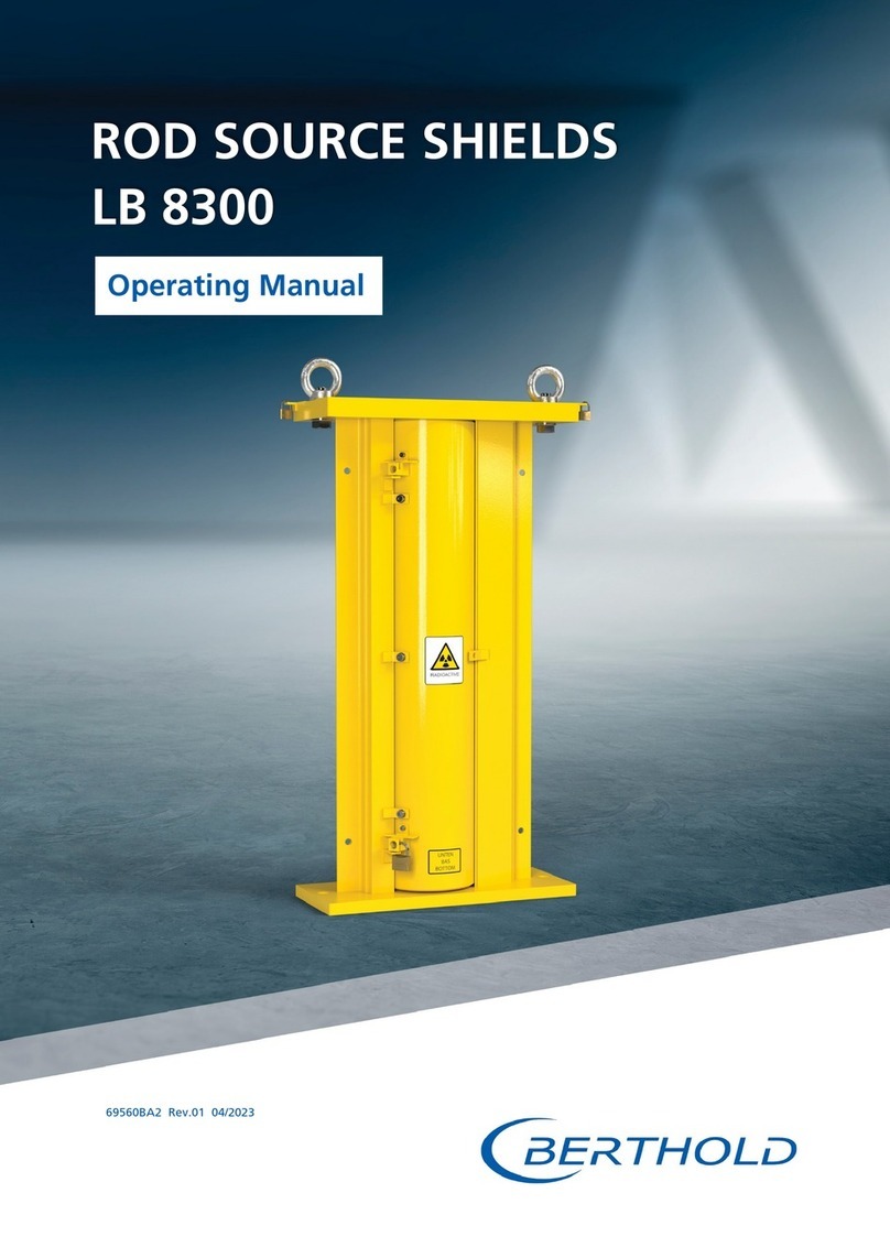
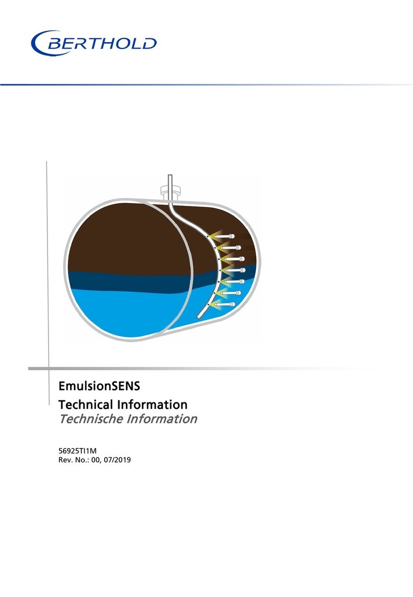
Berthold 40876-01 User manual

Shields for Flange Mounting
Operating Manual
44192BA2
Rev. No.: 03, 07/2021

BERTHOLD TECHNOLOGIES GmbH & Co. KG
Calmbacher Str. 22
75323 Bad Wildbad, Germany
www.berthold.com
Telephone +49 7081 177-0
Fax +49 7081 177-100

Shields for Flange Mounting Table of Contents
7 44192BA2, Rev.03, 07/2021
3
Operating Manual
1About this Operating Manual ............................................................................ 5
1.1 Applicable Documents ................................................................................................. 5
1.2 Some Prior Remarks...................................................................................................... 5
1.3 Storage .......................................................................................................................... 5
1.4 Target Group ................................................................................................................ 5
1.5 Validity of the Manual ................................................................................................. 6
1.6 Structure of the Manual............................................................................................... 6
1.7 Copyrights ..................................................................................................................... 6
1.8 Representation ............................................................................................................. 6
1.9 Symbols Used ................................................................................................................ 7
1.10 Structure of Warnings .................................................................................................. 8
1.11 Symbols used on the Device ........................................................................................ 8
2Safety .................................................................................................................. 9
2.1 Proper Use ..................................................................................................................... 9
2.2 Ambient Conditions during Operation and Storage ............................................... 10
2.3 Qualification of the Personnel .................................................................................. 10
2.4 Radiation Protection .................................................................................................. 12
2.5 Emergency Procedure................................................................................................. 14
2.7 Type Plate of the Source ............................................................................................ 15
3System Description ........................................................................................... 16
3.1 Variant Locking Cylinder............................................................................................ 17
3.2 Variant Lock Slide with Magazine............................................................................. 18
3.3 Variant Lock Slide ....................................................................................................... 19
4Transport .......................................................................................................... 20
4.1 Safety Instructions ...................................................................................................... 20
4.2 Packaging .................................................................................................................... 21
4.3 Intermediate Storage of the Source.......................................................................... 21
4.4 Scope of Delivery ........................................................................................................ 21
4.5 Transport to Operation Site....................................................................................... 21
5Installation ........................................................................................................ 22
5.1 Safety Instructions ...................................................................................................... 22
5.2 Preparing the Installation .......................................................................................... 23
5.3 Installation of the Shield............................................................................................ 24
5.4 Marking ....................................................................................................................... 28
6Usage ................................................................................................................ 29
6.1 Safety Instructions ...................................................................................................... 29
6.2 Commissioning............................................................................................................ 30
6.2.1 Open the Shutter........................................................................................................ 32
6.2.2 Inserting the Source into the Dip Pipe...................................................................... 33
7Maintenance and Repair .................................................................................. 35
7.1 Safety Instructions ...................................................................................................... 35
7.2 Visual Inspection of the Source Holder and Connections........................................ 36
7.3 Leak Test ..................................................................................................................... 38
7.4 Checking the Source Position and Shutter ............................................................... 40
7.5 Removing and Installing the Source ......................................................................... 41
7.5.1 Removing the Source ................................................................................................. 41
7.5.2 Installing the Source................................................................................................... 45
7.6 Source Replacement ................................................................................................... 47

Table of Contents Shields for flange mounting
4
44192BA2, Rev.03, 07/2021
8Decommissioning.............................................................................................. 48
8.1 Safety Instructions ...................................................................................................... 48
8.2 Disassemble the Shield ............................................................................................... 49
8.3 Disposal of Radioactive Substances........................................................................... 50
8.4 Shipment of Radioactive Substances......................................................................... 50
9Appendices ....................................................................................................... 52
9.1 Check Lists for Tests.................................................................................................... 52
Technical Information
Technical Data .................................................................................................... 1
Mounting Layouts............................................................................................... 3
Maximum permissible Activities during Transport ............................................ 4
Shields ................................................................................................................. 5
Variant DN 100 ............................................................................................................. 5
Variant DN 127 ............................................................................................................. 5
Variant DN 140 ............................................................................................................. 6
Variant DN 160 ............................................................................................................. 6
Variant DN 200 ............................................................................................................. 7
Variant DN 270 ............................................................................................................. 8
Variant LB 81xx (Point Source Shields)........................................................................ 9
Drawings Rod Source Shields ........................................................................... 10
Dimensions Variant DN 100 ....................................................................................... 10
Dimensions Variant DN 127 ....................................................................................... 11
Dimensions Variant DN 140 ....................................................................................... 12
Dimensions Variant DN 160 ....................................................................................... 13
Dimensions Variants DN 200...................................................................................... 14
Dimensions Variants DN 270...................................................................................... 18
Drawings Point Source Shields ......................................................................... 20
Dimensions LB 8115-01............................................................................................... 20
Dimensions LB 8115-02............................................................................................... 21
Dimensions LB 8115-20............................................................................................... 22
Dimensions LB 8120-01............................................................................................... 23
Dimensions LB 8120-02............................................................................................... 24
Dimensions LB 8120-20............................................................................................... 25
Dimensions LB 8120-30............................................................................................... 26
Dimensions LB 8125-01............................................................................................... 27
Shield with Lock Slide and Magazine .............................................................. 28

Shields for Flange Mounting 1 About this Operating Manual
44192BA2, Rev.03, 07/2021
5
1About this Operating Manual
1.1 Applicable Documents
This manual contains the following document:
•Technical Information, Mat. No. 44192TI (see appendix)
This operating manual does not contain the information required for pressure
retentive shields operation. The following document must be used for this purpose:
•Supplement for operating manual. Mat. No. 66938BA2
1.2 Some Prior Remarks
The product is handed over to you by the manufacturer BERTHOLD TECHNOLOGIES
GmbH & Co. KG (designated as Berthold in the following) in a complete and
functionally reliable condition.
This operating manual illustrates how to:
•set up/install the product
•operate the product
•carry out maintenance on the product
•disassemble the product
•dispose of the product
Read these instructions thoroughly and completely before working with the
product. We have tried to compile all the information for safe and proper
operation for you.
However, should questions arise which are not answered in this manual, please
contact Berthold. Store the instructions where they are accessible for all users at all
times.
1.3 Storage
This operating manual as well as all product-related documentation relevant to the
respective application must be accessible at all times during the life cycle near the
device.
1.4 Target Group
The product may only be installed, operated, maintained and repaired by trained
personnel.
This manual is directed at qualified specialist personnel who are familiar with
handling radioactive sources and heavy system components.
Specialist personnel refers to those who can assess the work assigned to them and
recognise possible dangers through their specialist training, knowledge and
experience as well as knowledge of the relevant regulations.

1 About this Operating Manual Shields for Flange Mounting
6
44192BA2, Rev.03, 07/2021
1.5 Validity of the Manual
The manual is valid from the delivery of the Berthold product to the user until its
disposal. Version and release date of this operating manual can be found in the
bottom of each page. An alteration service is not provided by the manufacturer
Berthold.
The manufacturer reserves the right to make changes to this operating manual at
any time without stating reasons.
NOTICE
The current revision of this operating manual replaces all previous versions.
1.6 Structure of the Manual
This manual has been divided into chapters. The order of the chapters should help
you to familiarise yourself quickly and properly with the operation.
1.7 Copyrights
This manual contains copyright-protected information. None of the chapters may
be copied or reproduced in any other form without prior authorisation from the
manufacturer.
1.8 Representation
Identifier
Meaning
Example
Round brackets
Image reference Connect the plug (fig. 1,
item 1)
Prohibited actions,
procedures or processes
within a figure.
Representation of the
ionizing radiation within
an figure.

Shields for Flange Mounting 1 About this Operating Manual
44192BA2, Rev.03, 07/2021
7
1.9 Symbols Used
NOTICE
If this information is not observed, deterioration in the operation and/or
property damage may occur.
IMPORTANT
Sections marked with this symbol point out important information on the
product or on handling the product.
Tip
Provides tips on application and other useful information.
General warning symbol
Warning symbol Danger of crushing
Warning symbol heavy loads
Warning symbol suspended load
Warning of radioactive substances
Wear protective helmet
Wear safety shoes
Do not touch the surface

1 About this Operating Manual Shields for Flange Mounting
8
44192BA2, Rev.03, 07/2021
1.10 Structure of Warnings
j
Signal word
Source and consequence
Explanation, if required
Measure
In case of emergency…
•Warning symbols: (warning triangle) draws attention to the hazard
•Signal word: states the severity of the hazard
•Source: states the type and source of the hazard
•Consequence: describes the consequences if warning is ignored
•Measure: states how one can avoid the hazard.
•In case of emergency: states how to react in case of direct danger.
Warning levels used
In this manual, warning instructions in front of instructions for action refer to risks
of injury or damage to property. The hazard-prevention measures described must
be observed.
j
DANGER
Indicates an
imminent
, major hazard, which will certainly result in serious
injuries or even death if the hazard is not avoided.
j
WARNING
Indicates a
potential
hazard, which can result in serious injuries or even death
if the hazard is not avoided.
j
CAUTION
Refers to a
potentially dangerous
situation, which can result in medium or
minor physical injuries or damages to property, if it is not avoided.
1.11 Symbols used on the Device
Ionising radiation
The shield is equipped with a radioactive source. Please note the handling
instructions. Please observe the transport instructions in this operating
manual.

Shields for Flange Mounting 2 Safety
44192BA2, Rev.03, 07/2021
9
2Safety
2.1 Proper Use
The source with shield is used in connection with a detector and a suitable
evaluation unit provided by Berthold to measure the radiation intensity occurring
during a radiometric measurement.
The shield was developed as shield/protective container for radioactive sources and
may be used exclusively for this purpose.
Usually, the shield contains a radioactive source. The notes on radiation protection
contained in the present manual as well as any statutory requirements in this
respect are to be strictly adhered to.
The following constitutes proper use:
•Adhering strictly to the instructions and operation sequences and not
undertaking any different, unauthorised practices which could put your safety
and the operational reliability of the shield at risk!
•Observing the provided safety instructions!
•Carrying out the prescribed maintenance measures or having them carried out
for you!
The following constitutes improper use and is to be avoided:
•Any non-compliance with the present operating manual for the supplied
products
•Applying conditions and requirements which do not conform to those stated in
the technical documents, data sheets, operation and assembly instructions and
other specific guidelines of the manufacturer.
•Using the product after any repair carried out by employees who have not been
authorized by Berthold.
•Using the product in a damaged or corroded condition.
•Dismounting the unit while the radiation beam outlet is open (except for
situations in which the shutter is defective and the beam outlet can no longer
be closed).
•Operation without the safety precautions provided by the manufacturer.
•Any modification to design and function, except for any activities provided for
and described in the present manual.
•Restructuring or changing the system components.
•Manipulation or avoidance of existing safety equipment.
Berthold shall only accept liability for / guarantee the correspondence of the
product to its publicised specifications.
If the product is used in a way which is not described in this manual, the product's
protection is compromised and the warranty becomes void.

2 Safety Shields for Flange Mounting
10
44192BA2, Rev.03, 07/2021
2.2 Ambient Conditions during Operation and Storage
The shield was specifically designed for use in rough ambient conditions. The
compliance with the operating conditions specified below contributes to
guaranteeing the permanent functionality of the shield and the prevention of
damage.
Shields containing radioactive substances and sources are to be stored in a lockable
storage room complying with the national requirements as regards the storage of
radioactive substances.
The higher the humidity, as well as the dust and dirt content of the environment,
the more likely stiffness or an entire blockage of the shutter is. For this reason, the
functional test intervals (see chapter 7) should be adjusted to the ambient
conditions.
Highly combustible or explosive substances must not be kept in the vicinity of
shields in order to prevent a fire from spreading to the radioactive substances.
Furthermore, the ambient conditions in the document “Technical Information”
(see appendix) are to be observed.
2.3 Qualification of the Personnel
NOTICE
A minimum requirement for all work on or with the product would be
employees with general knowledge who are instructed by an expert or
authorised person.
At different parts in this manual, reference is made to personnel with certain
qualifications who can be entrusted with different tasks during the installation,
usage and maintenance.
The four groups this refers to are:
•Employees with general knowledge
•Experts
•Authorised persons
•Radiation Safety Officer

Shields for Flange Mounting 2 Safety
44192BA2, Rev.03, 07/2021
11
Employees with General Knowledge
NOTICE
Employees with general knowledge must always be guided by one expert at
the very least. When dealing with radioactive substances, a radiation safety
officer must also be consulted.
Employees with general knowledge are e.g. technicians or welders who can
undertake different tasks during the transportation, assembly and installation of
the product under the guidance of an authorised person. This may also refer to
construction site personnel. The persons in question must have experience in
handling the product.
Experts
Experts are persons who have sufficient knowledge in the required area due to
their specialist training and who are familiar with the relevant national health
and safety regulations, accident prevention regulations, guidelines and
recognised technical rules.
Expert personnel must be capable of safely assessing the results of their work and
they must be familiar with the content of this manual.
Authorised Persons
Authorised persons are those who are either designated for the corresponding task
due to legal regulations or those who have been authorised by Berthold for
particular tasks. When dealing with radioactive materials, a radiation safety officer
must also be consulted.
Radiation Safety Officer
In order to ensure proper handling and compliance with the statutory
requirements, the company has to appoint a radiation safety officer in accordance
with the applicable national law (in Germany: Strahlenschutzverordnung [German
radiation protection regulation]). The radiation safety officer must implement the
statutory radiation protection requirements in order to protect employees against
damage to their health caused by handling radioactive materials.
NOTICE
Dangerous goods officers must not perform any activities as radiation
protection officers!
Radiation protection officers must have a special training with attendance of
an officially recognized course and appropriate professional experience.

2 Safety Shields for Flange Mounting
12
44192BA2, Rev.03, 07/2021
2.4 Radiation Protection
Basic Principles and Regulations
The amount of radiation absorbed by the body (exposure to radiation) is
determined by three parameters from which the basic radiation protection
regulations can be derived:
Distance
If work close to equipment containing
radioactive substances is required, the
largest distance possible is to be kept.
In particular, this shall apply for
employees which do not immediately
participate in such work.
Time
Any work required in the vicinity of
radiometric measuring systems is to be
prepared carefully and to be organised
in a way that the work can be executed
as quickly as possible. Here, providing
the correct tools and aids is particularly
important.
Shield
When mounting and dismounting the
shield, it is to be ensured in advance
that the radiation beam outlet is
closed.

Shields for Flange Mounting 2 Safety
44192BA2, Rev.03, 07/2021
13
Exposure of Employees to Radiation
During installation, maintenance and decommissioning of the shield, employees
may be exposed to radiation.
In order to keep such exposure as low as possible, the shield with the source may
only be mounted and/or dismounted by authorized employees. Such authorised
staff is to be instructed as regards all rules of behaviour when handling radioactive
substances in advance.
It is to be ensured that the shutter of the shield is closed and secured in order to
prevent the emission of unshielded radiation. Modification or damage to the shield
must be avoided at all times.
Work may only be executed according to the instructions and under the supervision
of the radiation safety officer, who furthermore has to calculate or estimate the
exposure of the employees to radiation in order to ensure that the statutory dose
rate limits are not exceeded.
Theft Protection
Radioactive substances or equipment containing radioactive substances must be
secured in a way that they are protected against access by unauthorized persons.
In the case of firmly installed equipment containing radioactive substances, the
protection against unauthorized access is generally provided by the firmly attached
installation.
Shields with radioactive sources which are decommissioned for a certain period of
time must be dismounted and securely stored in a storage room complying with
the national regulations as regards the storage of radioactive substances.
Portable measuring systems must never be left unsupervised. When this equipment
is out of use, it is to be protected against access by unauthorised persons.
In the Case of Fire
The shield material can melt and leak from the shield if exposed to very high
temperatures for an extended period of time. During and after a fire, there is a risk
of major long-time consequences for your health due to the incorporation of lead
as well as a risk of increased radiation exposure.
When planning the use of radiometric measuring systems, constructional measures
ensuring fire prevention are to be provided.
In the case of fire, these measures limit the access to this area.
Avoid the incorporation by keeping sufficient distance.
Notify Berthold of the situation; you will promptly receive information on
immediate measures.

2 Safety Shields for Flange Mounting
14
44192BA2, Rev.03, 07/2021
2.5 Emergency Procedure
In case of serious operational trouble, such as fire or explosion, which could
adversely affect the radiometric measuring facility, it cannot be ruled out that the
function of the shielding lock, the shielding efficiency or the stability of the source
capsule have been impaired. In this case, it is possible that persons in the vicinity of
the shielding have been exposed to higher levels of radiation.
If you suspect such a severe malfunction, the Radiation Safety Officer has to be
notified immediately. He will then investigate the situation immediately and take
all necessary provisions to prevent further damage and to avoid more exposure of
the operating staff to radiation.
The Radiation Safety Officer has to make sure that the measuring system is no
longer in operation and then take appropriate steps. He may have to inform the
authorities or contact the manufacturer or supplier of the measuring system.
If adequate know-how as well as suitable instruments are available, emergency
measures may be taken immediately. In this case, proceed as follows:
1. Locate the shield.
2. Check the function of the shielding.
3. Check the efficiency of the shielding by measuring the dose rate.
4. Secure and label radiation protection areas.
5. Secure the shielding with source.
6. Document the event and estimate the possible radiation level to which the
persons involved were exposed.
If you suspect any damage to the source capsule, the following points have to be
observed as well:
1. Avoid contamination.
2. Take hold of source using a tool (a pair of pliers or a pair of tweezers) and
put both (source and tool) into a plastic bag.
3. Secure them behind an auxiliary shielding (concrete wall, steel or lead plate).
4. Check if the environment is free of contamination.
5. Make sure the radioactive waste is secured and disposed off in compliance
with the pertinent regulatory requirements.

Shields for Flange Mounting 2 Safety
44192BA2, Rev.03, 07/2021
15
2.6 Operator's Obligations
The operator of the product must regularly train his personnel in the following
topics:
•Observation and use of the operating manual and the legal provisions.
•Proper use of the product.
•Observation of the plant security instructions and the operating instructions of
the operator
2.7 Type Plate of the Source
1
2
3
4
5
6
7
8
Date of manufacture of the source
Isotope
Activity [MBq]
Dose rate within 1 m distance [µSv/h]
Supplier of the source
Dose rate within 1 m distance [mrem/h]
Activity [mCi]
Source number
Fig.
1 Type plate of the source

3 System Description Shields for Flange Mounting
16
44192BA2, Rev.03, 07/2021
3System Description
Flange-mounted shields serve as shield and protective containers for radioactive
sources. The radioactive substance is located in a tightly sealed source capsule
within the shield. Flange mounting shields are available as shields for rod sources
or point sources in various designs.
Fig.
2 Top view shield head, variants 1 ... 16
Shields for flange mounting are used with measurement arrangements for which
the radioactive sources are stored inside a vessel during the measurement. The
sources can be moved from the shield into the measuring position by means of a
steel rope or a flexible shaft. Each source has its own suspension gear of different
length to place it at the particular positions.
The shield is mounted at a dip pipe, which protrudes into the vessel from above,
from below or at the side, depending on the constructive circumstances.
In addition to the sources and the shield, additional system components such as
detectors and evaluation units are required for a complete measuring system.
Usage of these system components is not subject of this operating manual. Please
refer to the individual manuals of the respective system components.
The shield vessel consists of a robust stainless steel housing filled with lead. In order
to close the shield, a rotatable locking cylinder is installed. The locking cylinder can
be rotated by means of a locking lever and be secured with a padlock.
The shield is mounted at the dip pipe by means of the fastening flange.

Shields for Flange Mounting 3 System Description
44192BA2, Rev.03, 07/2021
17
The shield has the following functions:
•Shield radiation to a level that is non-hazardous for the operating personnel
•Locking the radiation beam outlet channel for transport and during installation
•Protecting the integrated source capsule from mechanical damage and the
effects of the surrounding environment
3.1 Variant Locking Cylinder
1
2
3
4
5
Shield head with cover
Clamping screw
Coupling part of the source holder
Source holder
Source
6
7
8
9
Shield material
Locking cylinder (
CLOSED
position)
Housing
Locking lever
Fig.
3 Sectional view of a variant source with locking cylinder

3 System Description Shields for Flange Mounting
18
44192BA2, Rev.03, 07/2021
3.2 Variant Lock Slide with Magazine
1
2
3
Handle closure slide
Lock slide
Shield material
4
5
6
Shield head
Source Magazine
Clamping screw
Fig.
4 Sectional view of a variant point source with lock slide

Shields for Flange Mounting 3 System Description
44192BA2, Rev.03, 07/2021
19
3.3 Variant Lock Slide
1
2
3
4
Handle closure slide
Lock slide
Shield material
Shield head
5
6
7
Source passage
Claping screw
Flange adapter
Fig.
5 Sectional view of a variant point source with lock slide

4 Transport Shields for Flange Mounting
20
44192BA2, Rev.03, 07/2021
4Transport
The shield may only be transported by competent persons (see 2.3 Qualification of
the Personnel). Observe the national regulations applicable in the respective
country of use. If necessary, note the marking of the center of gravity on the
packaging.
4.1 Safety Instructions
j
WARNING
Danger of injury by falling loads!
Shields have built-in lead components increased weight.
Exclusively use the provided fixing possibilities (lifting eyes) for attaching
the sling gear.
Only use tested sling gear components appropriate for the transport
weight.
Never stand underneath a lifted or suspended load, keep at a safe
distance.
Wear head protection and safety shoes.
j
WARNING
Danger of injury caused by heavy and bulky system components!
Heavy and bulky system components should only be handled using aids
and by at least 2 persons.
Observe the guidelines for safe handling of heavy loads.
Ensure stability and use the provided fixing possibilities.
j
CAUTION
Danger caused by ionising radiation!
Shields usually contain radioactive sources. An increased exposure to radiation
may lead to damage to health.
Consult the radiation safety officer responsible for your company.
Transport the source exclusively inside the closed and secured shield.
The shutter must be in position
CLOSED
and secured during transport and
assembly of the shield.
NOTE
The device may only be transported by competent persons (see 2.3
Qualification of the Personnel).
This manual suits for next models
72
Table of contents
Other Berthold Industrial Equipment manuals
Popular Industrial Equipment manuals by other brands

Weber mt
Weber mt IVURplus 40 Operating and maintenance manual

Pepperl+Fuchs
Pepperl+Fuchs R2-SP-IC Series manual

PCB Piezotronics
PCB Piezotronics ICP 320C15 Installation and operating manual

Siemens
Siemens 3RS17 Series operating instructions

Mayer
Mayer TM 2020F manual

Dixon
Dixon BAYCO BC Series Maintenance instructions