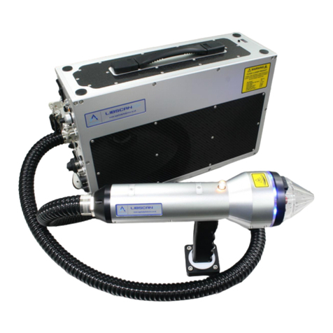
Applied Photonics LIBS-6 User manual

Modular
Laser-Induced Breakdown Spectroscopy (LIBS)
System
User’s Manual for Example Configuration 1
June 2022
Applied Photonics Ltd
Unit 8 Carleton Business Park, Skipton, North Yorkshire BD23 2DE, United Kingdom
Tel +44 (0) 1756 708900 Fax +44 (0) 1756 708909 Web: www.appliedphotonics.co.uk
© 1998 - 2022 Applied Photonics Ltd

© 1998 - 2022 Applied Photonics Ltd Page 2 of 41
Contents Page
1. Introduction 3
2. Safety 3
2.1 Laser radiation 3
2.2 Note on the laser safety window material used in the modular sample chambers 6
2.3 Electrical 6
3. General description 7
3.1 Overview 7
3.2 Laser beam expander and plasma light collection optics 11
3.3 Right-angle Mirror Module 12
3.4 Attaching the LIBS-6 / LIBS-8 module to a laser 12
3.4.1 Adaptor Platforms 12
3.4.2 Litron Nano SG 150-10 (1064 nm) laser 13
3.4.3 Litron Nano LG 300-10 (1064 nm) laser 14
3.4.4 Configuration options 14
3.5 Modular sample chambers 16
3.5.1 Overview 16
3.5.2 XYZ-750 computer-controlled sample chamber 17
3.5.3 SC-2L modular sample chamber 18
3.6 SpectroModule-6 and SpectroModule-8 multi-channel LIBS spectrometers 20
3.7 Fibre-optic connections 22
3.8 Electrical connections 24
3.9 Imaging camera and associated components 25
3.10 Gas purge feature and air pump 27
3.11 LIBSoft software 28
3.12 System computer specifications 28
3.13 Setting the position of the acrylic nozzle aperture 29
3.14 Adjusting and setting the laser beam focus 30
3.15 Using an energy meter to measure the laser pulse energy 31
3.16 Important note on back-reflections of laser radiation 32
4. Assembly of the LIBS equipment 34
4.1 Introduction 34
4.2 Step-by-Step guide to configuring the LIBS equipment 34
5. Operating procedure 37
5.1 Introduction 37
5.2 Step-by-Step guide to operating the LIBS equipment 37
6. Shut-down procedure 39
7. Operating the LIBS equipment in “open beam” configuration 39
8. Maintenance and inspection 40
9. Shipping and storage 40
10. Trouble-shooting / fault finding 40

© 1998 - 2022 Applied Photonics Ltd Page 3 of 41
1 Introduction
The modular Laser-Induced Breakdown Spectroscopy (LIBS) system described in this User’s Manual is
designed to be a highly versatile product for use by research scientists, application engineers and OEMs.
Essentially a “LIBS system building block”, the LIBS-6 and LIBS-8 modules may be used together with a
variety of Q-switched Nd:YAG lasers and optical spectrometers to form a customised, modular LIBS
system tailored to suit the requirements of a specific application or experimental research project. The
LIBS modules remove the need for the research scientist or application engineer to design and construct
their own laser focussing optics and plasma light collection optics by combining these features into a
compact, integrated and easy to use device. An optional imaging kit may be added to the LIBS module,
increasing further its functionality and versatility.
The modular LIBS system described in this User’s Manual comprises the following main components: a
LIBS-6 module fitted with an optional imaging camera (IMG-HR), an AP-Nano adaptor platform, a
Litron Nano SG 150-10 laser, a SpectroModule-6 multi-channel LIBS spectrometer, an SC-2L modular
sample chamber and a computer running LIBSoft software. In some sections of this User’s Manual, the
following components and devices are also described: LIBS-8 module, SpectroModule-8 six-channel
LIBS spectrometer, Litron Nano LG 300-10 laser, an XYZ-750 modular sample chamber and a dual-
camera imaging system (IMG-HR-2).
This User’s Manual provides the necessary information needed to configure the LIBS equipment and how
to operate the equipment safely. It is assumed that the user is familiar with the safety issues arising from
the use of high-power lasers and will have preferably been trained in the safe use of high-power (Class 4)
laser products.
2 Safety
2.1 Laser radiation
The modular LIBS system utilises a high-power Q-switched Nd:YAG laser (Class 4) and so it is
imperative the equipment is operated only by suitably trained and experienced persons who are fully
aware of the hazards inherent to this type of high-power laser equipment. It is imperative also that, prior
to using the equipment, an appropriate risk assessment is conducted in such a way as to take account of
the proposed use of the equipment, the environment in which the equipment is to be operated, and how its
use may affect people who are not directly involved with the use of the equipment.
Example of a laser warning product label
The modular LIBS system is designed to meet the laser safety requirements of the relevant European
standards (BS EN 60825) and USA standards (ANSI Z136.1). Although the modular LIBS system is
supplied with a sample chamber which provides adequate containment of the laser radiation to Class 1
Accessible Emission Limits, it is possible for the user to operate the LIBS equipment without the sample
chamber (i.e. operation in “open beam” mode as may be required for certain types of experiment).
Accordingly, it is necessary to consider the modular LIBS system to be a Class 4 Laser Product and so,
by definition, the equipment poses a risk of personal injury (eye, skin injury) and poses a fire risk. As

© 1998 - 2022 Applied Photonics Ltd Page 4 of 41
with all Class 4 laser products, appropriate safety precautions must be taken as identified via a suitable
risk assessment conducted by the user in consultation with a suitably qualified and experienced Laser
Safety Officer.
The most significant hazard relating to exposure of personnel to the laser radiation is eye injury since
direct or scattered laser radiation produced by the equipment can cause serious and permanent injury to
the eyes including blindness - such injury may be instantaneous. Precautions must be taken to avoid
exposure of personnel to hazardous levels of laser radiation. Such precautions may include the setting up
of a temporary or permanent laser controlled area (e.g. a laser laboratory). Other measures may also be
necessary, as determined by appropriate and thorough assessment of the risks (i.e. a risk assessment)
conducted by the personnel responsible for the safe use of the laser equipment. Consult the User’s
Manual supplied with the laser for further guidance on the safe use of the laser.
The door of the sample chamber is equipped with a dual electrical interlock switch which is designed to
prevent activation of the laser unless the door is fully closed. The door interlock switch is electrically
connected to the “Interlock In/Out” port on the LIBS module via the 9-pin connector located directly
above the laser aperture. The “Interlock In/Out” port connects with the SpectroModule-8 (using the
supplied lead) which in turn is connected to the interlock circuits of the laser power supply. The laser
safety interface between the SpectroModule-8 and the laser power supply depends on the make and model
of laser being used. Throughout this User’s Manual, it is assumed that a Litron NANO SG 150-10 laser
and associated power supply is used, together with an SC-2L 3-axis manually-controlled sample chamber.
Removal of the sample chamber from the LIBS-6 module, or disconnection of the Interlock In/Out lead,
will also activate the interlock (i.e. prevent activation of the laser). The SpectroModule-6 multi-channel
LIBS spectrometer is equipped with an Interlock Override facility (a keyswitch) which allows the
interlock to be disabled so that the LIBS system may be used without a sample chamber (i.e. “open beam”
mode). In view of this, the modular LIBS system must be categorised as a Class 4 laser product since,
by design, the product may be used in such a way that the laser beam is not contained (i.e. “open beam”
mode of operation).If, however, the sample chamber is correctly fitted to the LIBS-6 module and the
Interlock Override keyswitch is switched off and the key removed, then the laser radiation is adequately
contained to Class 1 Accessible Emission Limits by the design of the hardware.
IMPORTANT
•READ and UNDERSTAND both this User’s Manual and the instructions provided by the
manufacturer of the laser before operating the LIBS equipment.
•ENSURE that an appropriate risk assessment has been conducted to establish whether or not the
laser safety windows fitted to the modular sample chambers provide adequate protection against
exposure to laser radiation for the specific laser you intend to use with the LIBS equipment.
For advice on this matter, consult your Laser Safety Officer and/or Applied Photonics Ltd.

© 1998 - 2022 Applied Photonics Ltd Page 5 of 41
•ONLY suitably qualified and authorised persons should activate the Interlock Override keyswitch.
The key should be removed from the keyswitch and held by the Laser Safety Officer when this
feature is not required.
•ALWAYS use appropriate laser safety protective eyewear when operating the LIBS equipment in
“open-beam” configuration –you should seek advice from your Laser Safety Officer on this
matter.
•ALWAYS switch the laser off when not in use and remove the key from the keyswitch of the laser
power supply to prevent unauthorised activation.
•ALWAYS thoroughly inspect the LIBS equipment for damage prior to use. Particular attention
should be given to the laser safety windows and the laser safety interlock system, which should be
tested each time the equipment is used.
•NEVER allow unauthorised and/or untrained persons operate the LIBS equipment.
•NEVER operate the LIBS equipment in areas where explosive gas mixtures may be present.
•NEVER operate the LIBS equipment with any access cover, panel, or protective window
removed.
•NEVER place inside the sample chamber flammable liquids or any other material which may give
rise to flammable / explosive gas mixtures. Activation of the laser under these conditions could
result in an explosion leading to severe personal injury and/or fire hazard. Remember that the
laser-induced plasma is a source of ignition.
•NEVER point the LIBS laser beam at a person (even with laser switched off), especially towards
the eyes, even if the person is wearing laser safety eyewear. The laser should be considered
“active” unless the laser power supply is fully deactivated.
•NOTE that the transparent acrylic nozzle aperture of the LIBS-6 or LIBS-8 module does not
provide any protection to the user against exposure to direct or scattered laser radiation. The
function of the nozzle aperture is described later in this User’s Manual.
Image of LIBS-6 module showing location of laser warning
indicator lights, laser aperture and warning label
Laser warning
indicator lights
Laser aperture
warning label
Laser aperture
Transparent nozzle
aperture
Electrical connection to
SpectroModule-6 (-8) or
Interlock Interface Unit
Camera setup
joystick
LED
intensity
Electrical
connection to
sample chamber

© 1998 - 2022 Applied Photonics Ltd Page 6 of 41
2.2 Note on the laser safety window material used in the modular sample chambers
The laser safety window material fitted to the sample chamber is rated as follows:
Laser
Wavelength
(nm)
USA Standard
ANSI Z 136.1 –2014
UK & European Standard
BS EN 207:2017
Optical
Density
Protection Level R
(Q-switched laser)
1064
OD 6+
L6
355
OD 5+
L5
266
OD 5+
L5
R L6 at 1064 nm indicates a protection level of maximum spectral transmittance of 10-6 at 1064 nm for a
pulsed laser of pulse length 10-9 –10-7 seconds (i.e. a Q-switched laser).
The laser safety windows used in Applied Photonics Ltd’s range of modular sample chambers provide
adequate protection against scattered laser light of wavelength 1064 nm, 355 nm and 266 nm such that
Class 1 Accessible Emission Limits are met if the sample chamber is used correctly and laser pulse
energies are not excessively high (i.e. typically less than 300 mJ with a 5 - 10 ns pulse length). Note that
the protective windows are NOT suitable for use with a 532 nm laser. Given that the LIBS-6 and LIBS-8
modules may be used with a variety of lasers, it is the responsibility of the user to conduct a risk
assessment to establish whether or not the laser safety windows provide adequate protection for the
particular laser being used. If in any doubt, you should consult your Laser Safety Officer and/or Applied
Photonics Ltd for advice on this matter.
Warning –the Applied Photonics Ltd modular sample chambers are designed specifically for use
with our LIBS-6 / LIBS-8 integrated LIBS modules and our LIBSCAN range of products and
should not be used with any other laser device or product. If in doubt, seek advice from the
manufacturer, Applied Photonics Ltd.
2.3 Electrical
The LIBS-6 and LIBS-8 integrated LIBS modules, the SpectroModule-6 / SpectroModule-8 multi-
channel LIBS spectrometer and the XYZ-750 modular sample chamber contain electrical circuits
operating at 12 VDC at a maximum current of 5 Amps. Accordingly, they pose no electric shock risk.
The laser head and associated power supply, however, contain electrical circuits operating at potentially
lethal voltage and current levels. Consult the manufacturer’s User Manual supplied with the laser for
further guidance on the safe use and routine maintenance of the laser.

© 1998 - 2022 Applied Photonics Ltd Page 7 of 41
3 General description
3.1 Overview
The modular LIBS system used in Example Configuration 1 consists of the following main components:
•LIBS-6 module (1064 nm) Qty 1
•Right-angle mirror module (1064 nm) Qty 1
•Adaptor Platform (AP-Nano) Qty 1
•Litron Nano SG 150-10 laser (1064 nm) Qty 1
•SpectroModule-6 multi-channel LIBS spectrometer Qty 1
•SC-2L manually-controlled sample chamber Qty 1
•Imaging kit IMG-HR (single camera) Qty 1
•LIBSoft software Qty 1
In addition to the above components, for completeness this User’s Manual includes information on
selected other components such as a LIBS-8 module, a SpectroModule-8 spectrometer, an XYZ-750
computer-controlled sample chamber and a dual-camera imaging system (IMG-HR-2).

© 1998 - 2022 Applied Photonics Ltd Page 8 of 41
The main components of the LIBS-6 and LIBS-8 integrated LIBS module are illustrated in the following
figures. The LIBS-8 module is essentially identical to the LIBS-6 module except that it has eight plasma
light collection channels rather than six.

© 1998 - 2022 Applied Photonics Ltd Page 9 of 41
The LIBS modules include the following features:
•Plasma light collection lens array (six or eight channels) having a relatively large depth-of-field to
allow efficient light collection even when the plasma position varies by approximately ±3 mm
along the optic axis of laser beam.
•3-lens laser beam expander with adjustable focus (adjustment of focal plane made by rotating the
brass beam expander lens holder via the cut-way in the laser beam tube –adjustment range of
approx. 14 mm).
•Adjustable nozzle aperture which provides a convenient means of setting the distance to the
sample surface (adjustment range of approx. 14 mm). The nozzle aperture may be removed if this
feature is not required.
•Gas-purge port (accepts 4 mm flexible nylon tube) which may be used to feed inert gas (e.g.
argon, helium, nitrogen) to the sample surface. To ensure purge gas is directed to the sample, it is
necessary to fit the nozzle aperture.
•Optional miniature CMOS colour video camera with array of dimmable high-brightness white
LEDs for illuminating sample surface.
•Laser safety interlock with keyswitch operated override facility (via the SpectroModule-6 or
SpectroModule-8 multi-channel LIBS spectrometer or an Interlock Interface Unit if an alternative
spectrometer is used).
•Compatible with the Applied Photonics Ltd (APL) range of modular sample chambers.
Laser
warning
light
Transparent
nozzle
aperture
Plasma light
collection
lens holder
Threaded
ring
Front
bulkhead
Camera
housing
High-
intensity
LEDs
Optics
array
Gas-purge
port
Electrical connection
(to sample chamber)
High-intensity
LED dimmer
control
Laser
interlock
connection
Tie-bar
Laser beam tube
Lock
screw
Fibre-optic
cable
Beam
expander
Rear
bulkhead
Electronics enclosure
Cut-away to allow adjustment
of laser focus

© 1998 - 2022 Applied Photonics Ltd Page 10 of 41
Front view of LIBS-8 module showing plasma light collection lens array,
CMOS 2.5 MP camera, LED lights, laser aperture and gas purge outlet
Front view of LIBS-6 module showing plasma light collection lens array,
CMOS 2.5 MP camera, LED lights, laser aperture and gas purge outlet
Miniature CMOS
2.5 MP camera
(optional feature)
Two high-brightness white
LED lights
(optional feature as part of
the IMG-HR kit)
Circular array of eight lens
holders –used to collect
plasma light. The purple lens
holder is for collection of
Deep-UV, the blue lens
holders are for collection of
UV-VIS while the red lens
holders are for collection of
VIS-NIR.
Laser warning
indicator lights
Electrical connection
to sample chamber
Laser beam expander
and output aperture
Grub screw for locking
aperture nozzle (do not
over-tighten)
Gas purge outlet
Four high-brightness white
LED lights
(optional feature as part of
the IMG-HR kit)
Circular array of six lens
holders –used to collect
plasma light. The purple lens
holder is for collection of
Deep-UV, the blue lens
holders are for collection of
UV-VIS while the red lens
holders are for collection of
VIS-NIR.
Gas purge outlet

© 1998 - 2022 Applied Photonics Ltd Page 11 of 41
3.2 Laser beam expander and plasma light collection optics
The optical configuration used in the LIBS-6 and LIBS-8 modules is illustrated schematically in the
following diagram. The laser beam expander consists of three lenses and is used to provide a tightly
focussed laser beam at nominally 100 mm from the aperture of the beam expander. The optical design is
specific to the make and model of laser which the LIBS-6 or LIBS-8 module is to be used with –this is
specified at the time of ordering of the LIBS module. The brass tubular piece which houses the beam
expander lenses is threaded (1 mm pitch thread) so that rotating it causes the focal plane of the laser beam
to move. The design allows for approximately ±7 mm of adjustment, as illustrated in the following
diagrams. The plasma light collection optics are angled at approximately 17 degrees and are designed to
collect light from the region in space defined in the following diagram. The transparent nozzle aperture is
threaded so that rotation causes it to move along the optic axis of the laser beam –range of travel is
approximately ±7 mm. The nozzle aperture may be removed from the body of the LIBS-6 or LIBS-8
module by unscrewing further or by removing the threaded black acrylic piece it screws into by
unscrewing the four M4 cap head screws. The main purpose of the transparent nozzle aperture is to
provide a convenient means of setting the distance to the sample surface. The nozzle aperture also
provides containment of the purge gas, if used, to ensure the sample surface and laser-induced plasma
region are effectively purged of atmospheric air. Physical protection for the laser beam optics and plasma
light collection optics (and imaging camera if fitted) is also provided by the nozzle aperture.
Adjustment range of focal
plane of laser beam
(approx. ±7 mm)
Adjustment range of
transparent aperture nozzle
(approx. ±7 mm)
Transparent
aperture nozzle
Brass holder
containing laser beam
expander lenses
Threaded section
Threaded section
Laser Beam
Laser Beam
Fibre-optic cable
to spectrometer
Fibre-optic cable
to spectrometer

© 1998 - 2022 Applied Photonics Ltd Page 12 of 41
3.3 Right-angle Mirror Module
The right-angle Mirror Module is fitted between the Adaptor Platform and the LIBS-6 / LIBS-8 module
and is required if one of APL’s “top entry” modular sample chambers (e.g. XYZ-750, SC-2L, SC-2XL
etc) is used with the LIBS equipment.
Mirror Module (1064 nm)
Internal view of Mirror Module showing laser beam path
The Mirror Module provides precise alignment of the laser beam for the LIBS-6 / LIBS-8 module which
is attached to the output side of the mirror module. Optical alignment is carried out at APL during final
assembly of the LIBS equipment and so there should be no need for the user to adjust the internal mirror
assembly. The Mirror Module, Adaptor Platform and LIBS-6 / LIBS-8 module each include dowel pin
fittings so that precise optical alignment is maintained on removing and refitting these components. If
you suspect that the optical alignment of the laser beam has been compromised, contact APL for advice
before attempting to realign the optics.
3.4 Attaching the LIBS-6 / LIBS-8 module to a laser
3.4.1 Adaptor Platforms
The LIBS-6 / LIBS-8 modules are suitable for use with virtually any commercially-available Q-switched
Nd:YAG laser which has operating characteristics appropriate for LIBS. In order to attach either the
LIBS-6 or LIBS-8 module to a laser head, it is necessary to use an appropriate adaptor platform. At the
time of writing of this User’s Manual, Applied Photonics Ltd supplies adaptor platforms for the following
lasers:
Laser Product
Adaptor Platform
Quantel Brilliant and Brilliant B
AP-Brilliant
Quantel (Big Sky) Ultra CFR range of lasers
AP-Ultra
Quantel (Big Sky) CFR 200 range of lasers
AP-CFR200
Quantel (Big Sky) CFR 400 range of lasers
AP-CFR400
Quantel QSmart 450 and 850
AP-QSmart
Innolas SpitLite
AP-SpitLite
Ekspla
AP-Ekspla
Litron Nano
AP-Nano
Litron Nanolite
AP-Nanolite
Litron Bernoulli (double-pulse, 1064 nm & 266 nm)
AP-Bernoulli
Should your laser not be listed above, contact Applied Photonics Ltd to enquire about availability of a
suitable adaptor platform giving details of the make and model of your laser.
Input laser
beam
Output
laser beam
M5 x 16 fixing screws to Adaptor Platform
(Qty 2 per side)

© 1998 - 2022 Applied Photonics Ltd Page 13 of 41
3.4.2 Litron Nano SG 150-10 (1064 nm) laser
The Litron Nano SG 150-10 laser head fits to the Adaptor Platform (AP-Nano) as shown in the following
illustrations. The Litron NANO SG 150-10 laser head is attached to the eight steel pillars on the adaptor
platform using eight M6x16 cap head screws. Two alignment pillars (fitted by Applied Photonics Ltd
during final assembly) are used to provide a means for correctly aligning the laser head with respect to the
adaptor platform. These alignment pillars should not be removed or adjusted by the user as they provide
critical optical alignment of the laser beam for the laser head supplied with the equipment.
The laser head baseplate should be in contact with the M4 grub screws located in each alignment pillar to
achieve correct optical alignment of the laser beam. This is achieved by sliding the laser head up against
the two alignment pillars before fully tightening the six fixing screws used to attach the laser head
baseplate (with attached laser head) to the adaptor platform.
Steel pillars
Alignment pillars
Alignment pillars
Litron Nano SG 150-10
laser head (1064 nm)
Laser head
baseplate
Alignment pillar
with M4 grub screw
Alignment pillar
with M4 grub screw
Elongated counter-
bores in laser head
baseplate to allow
lateral movement
Litron Nano SG 150-10
laser head (1064 nm)
AP-Nano Adaptor Platform
AP-Nano Adaptor
Platform
M4 grub screw in
contact with laser
head baseplate
Beam
tube
Beam tube
Laser head
baseplate
Litron Nano SG 150-10
(1064 nm) laser head
4 x 10 mm dowel pins
(qty 2)
M4 x 16 Attachment screws
(qty 2)

© 1998 - 2022 Applied Photonics Ltd Page 14 of 41
3.4.3 Litron Nano LG 300-10 (1064 nm) laser
The Litron Nano LG 300-10 laser head is attached
to the eight steel pillars on the adaptor platform
using eight M6x16 cap head screws. Two
alignment pillars (fitted by Applied Photonics Ltd
during final assembly) are used to provide a means
for correctly aligning the laser head with respect to
the adaptor platform. These alignment pillars
should not be removed or adjusted by the user as
they provide critical optical alignment of the laser
beam for the laser head supplied with the
equipment.
Close-up view of the front alignment pillar
The metal body of the laser head should be in
contact with the M4 grub screws located in each
alignment pillar to achieve correct optical
alignment of the laser beam. This is achieved by
sliding the laser head up against the two alignment
pillars before fully tightening the eight M6 x 16
fixing screws used to attach the laser head to the
adaptor platform.
Close-up view of the rear alignment pillar
The laser head should not be removed from the
adaptor platform unless absolutely necessary (e.g.
should the laser head need to be returned to the
manufacturer for repair etc).
Note: Do not remove or adjust the alignment pillars
/ M4 grub screws without first contacting Applied
Photonics Ltd for advice.
3.4.4 Configuration options
The LIBS-6 / LIBS-8 modules may be attached to the Adaptor Platform in various ways, as shown in the
following CAD illustrations.
Mirror Module attachment to the Adaptor Platform
Alignment pillars with M4 grub screws
Steel pillars
Dowel pins
(qty 2)
M5 x 16 fixing screws
(qty 2 each side)

© 1998 - 2022 Applied Photonics Ltd Page 15 of 41
The following configuration is used with our “top entry” sample chambers such as our SC-2L and XYZ-
750 products. This configuration may also be used in situations where a sample chamber is not required
but the laser beam is required to interact with the sample vertically from above.
Mirror Module and LIBS-6 / LIBS-8 module attachment to the Adaptor Platform
The following configuration is used with our “side entry” sample chambers such as our SC-1 and SC-2
products. This configuration may also be used in situations where a sample chamber is not required but
the laser beam is required to interact with the sample horizontally.
LIBS-6 / LIBS-8 module attachment to the Adaptor Platform without use of a Mirror Module
Dowel pins in the mating surfaces of the Adaptor Platform and modules are used to maintain correct
optical alignment allowing the user to reconfigure the hardware without undertaking a full optical
realignment of the laser beam optics.
Dowel pins
(qty 2)

© 1998 - 2022 Applied Photonics Ltd Page 16 of 41
3.5 Modular sample chambers
3.5.1 Overview
A range of modular sample chambers is available for use with the LIBS-6 / LIBS-8 modules (see table
below). These sample chambers are also suitable for use with our LIBSCAN range of products. The
XYZ-750 and SC-2L sample chambers are described in more detail in the remainder of this User’s
Manual.
SC-1
SC-2C
SC-2M
SC-2L
Single axis translation stage, 20
mm travel per stage (manual
control).
Approx. overall dimensions: 110 x
120 x 210 mm, approx. 2.0 kg
2-axis translation stage, 20 mm
travel per stage (manual control).
Approx. overall dimensions: 110 x
120 x 260 mm, approx. 2.5 kg
2-axis translation stage, 20 mm
travel per stage (manual control)
Fume extract port. Internal LED
light.
Approx. overall dimensions: 160
x 160 x 260 mm, approx. 4.0 kg
3-axis translation stage, 50 mm
travel per stage (manual control).
Fume extract port. Internal LED
light.
Approx. overall dimensions: 280 x
250 x 330 mm, 14 kg
SC-2XL
XYZ-750
XYZ-2500
SC-LQ2
3-axis translation stage, 50 mm
travel per stage (manual control).
Fume extract port. Internal LED
light.
Approx. overall dimensions: 330 x
360 x 430 mm, approx. 18 kg
3-axis translation stage, 75 mm
travel per stage (computer-
controlled). Fume extract port.
Internal LED light.
Approx. overall dimensions: 330 x
360 x 480 mm, approx. 21 kg
3-axis translation stage, X & Y
travel = 250 mm, Z travel = 100
mm (computer-controlled). Fume
extract port. Internal LED light.
Approx. overall dimensions: 470
x 770 x 730 mm, approx. 56 kg
Modular sample chamber designed
to analyse liquids. Further details
can be found in APL Tech Note
#6. Approx. 19 kg
Current range of modular sample chambers manufactured by Applied Photonics Ltd
WARNING
The above range of modular sample chambers is designed specifically for use with the LIBS-6 / LIBS-8
integrated LIBS modules or the LIBSCAN range of modular LIBS systems. The specifications for the
laser safety windows are as follows:
Laser
Wavelength
(nm)
USA Standard
ANSI Z 136.1 –2014
UK & European Standard
BS EN 207:2017
Optical
Density
Protection Level R
(Q-switched laser)
1064
OD 6+
L6
355
OD 5+
L5
266
OD 5+
L5
R L6 at 1064 nm indicates a protection level of maximum spectral transmittance of 10-6 at 1064 nm for a
pulsed laser of pulse length 10-9 –10-7 seconds (i.e. a Q-switched laser).
Since the LIBS-6 / LIBS-8 integrated LIBS modules may be used with various laser devices, it is the
responsibility of the user to establish whether the protection offered by the laser safety windows is
adequate for the laser being used. If in doubt, seek advice from a suitably qualified Laser Safety Officer
or contact Applied Photonics Ltd before operating the laser equipment.

© 1998 - 2022 Applied Photonics Ltd Page 17 of 41
3.5.2 XYZ-750 computer-controlled sample chamber
The XYZ-750 computer-controlled sample chamber is one of APL’s range of modular sample chambers
designed for use with APL’s modular LIBS systems. The XYZ-750 requires LIBSoft software to operate
as it has no manual control of the three stages.
XYZ-750 computer-controlled,
modular sample chamber
XYZ-750 with triangular support brackets fitted
(for laser head Adaptor Platform)
The XYZ-750 has the following features:
•3-axis motorised and computer-controlled translation stages each with 75 mm travel
•Precision ball-screw design which reduces rotational friction and virtually eliminates mechanical backlash
•Heavy-duty linear rail bearings (two rails per stage)
•Translation stage linear resolution of 1 µm
•Sample table breadboard with array of M6 tapped holes on 25 mm centres (5 kg load rating)
•Hinged door with magnetic catch and dual redundant electrical safety interlock
•Laser protective windows on two sides and hinged door
•Fume extraction port with internal flexible tube (external fume extraction system not included)
•Internal lighting
•External dimensions of approx. 330 x 360 x 430 mm. Weight approx. 21 kg
XYZ-750 front view XYZ-750 rear view
Dual microswitches and
magnetic catches for
sample chamber door
Flexible fume
extraction tube
12 VDC
power in
Sample
table
Emergency Off (E-Off)
switch. Disables both the
laser and the movement
of the X, Y and Z stages
of the sample chamber
USB
port
Fume
extraction port
(1/2” BSPP)
E-Off switch
activated lamp

© 1998 - 2022 Applied Photonics Ltd Page 18 of 41
3.5.3 SC-2L modular sample chamber
The SC-2L manually-operated sample chamber is one of APL’s range of modular sample chambers
designed for use with APL’s modular LIBS systems.
SC-2L modular sample chamber
SC-2L with triangular support brackets fitted
(for laser head Adaptor Platform)
The SC-2L has the following features:
•3-axis manually-operated translation stages each with 50 mm travel
•Precision ball-screw design which reduces rotational friction and virtually eliminates mechanical backlash
•Heavy-duty linear rail bearings (two rails per stage)
•Translation stage linear resolution of 2.5 mm per revolution (125 µm per division on adjuster knob)
•Sample table breadboard with array of M6 tapped holes on 25 mm centres (5 kg load rating)
•Hinged door with magnetic catch and dual redundant electrical safety interlock
•Laser protective windows on two sides and hinged door
•Fume extraction port with internal flexible tube (external fume extraction system not included)
•Internal lighting
•External dimensions of approx. 260 x 260 x 320 mm. Weight approx. 14 kg
SC-2L front view SC-2L rear view
Dual microswitches and
magnetic catch for
sample chamber door
Flexible fume
extraction tube
Sample
table
Fume
extraction port
(1/2” BSPP)
Adjustment knob
for z-axis
translation stage
Adjustment knob
for y-axis
translation stage
Adjustment knob
for x-axis
translation stage

© 1998 - 2022 Applied Photonics Ltd Page 19 of 41
Close-up view of inside of XYZ-750 sample chamber with LIBS-6 module fitted
and showing a laser-induced plasma on a metallic sample (high-purity gadolinium)
Close-up view of inside of XYZ-750 sample chamber with LIBS-6 module fitted
and showing a laser-induced plasma on a metallic sample (CZ121 brass)
Fume extract
nozzle
Breadboard sample table (with array of M6 tapped holes on 25 mm centres)
Sample
Laser
plasma

© 1998 - 2022 Applied Photonics Ltd Page 20 of 41
3.6 SpectroModule-6 and SpectroModule-8 multi-channel LIBS spectrometers
The SpectroModule-6 and SpectroModule-8 multi-channel LIBS spectrometers are illustrated in the
following diagrams.
SpectroModule-6 six-channel LIBS spectrometer
SpectroModule-8 eight-channel LIBS spectrometer
SpectroModule-6 is fitted with up to six optical spectrometers whereas SpectroModule-8 is fitted with up
to eight optical spectrometers. The spectrometer specifications are as follows:
SpectroModule-6
Six-channel LIBS spectrometer
SpectroModule-8
Eight-channel LIBS spectrometer
Spectrometer channel 1 (Spec-1)
Approx. 190 –261 nm, 3600 grating, FWHM = approx. 0.05 nm
Spectrometer channel 2 (Spec-2)
Approx. 260 –320 nm, 3600 grating, FWHM = approx. 0.05 nm
Spectrometer channel 3 (Spec-3)
Approx. 319 –421 nm, 2400 grating, FWHM = approx. 0.07 nm
Order sorting filter: OSF-305
Spectrometer channel 4 (Spec-4)
Approx. 420 –503 nm, 2400 grating, FWHM = approx. 0.07 nm
Order sorting filter: OSF-395
Spectrometer channel 5 (Spec-5)
Approx. 502 –721 nm, 1200 grating, FWHM = approx. 0.14 nm
Order sorting filter: OSF-475
Spectrometer channel 6 (Spec-6)
Approx. 720 –910 nm, 1200 grating, FWHM = approx. 0.14 nm
Order sorting filter: OSF-600
Spectrometer channel 1 (Spec-1)
Approx. 182 –254 nm, 3600 grating, FWHM = approx. 0.04 nm
Spectrometer channel 2 (Spec-2)
Approx. 252 –312 nm, 3600 grating, FWHM = approx. 0.04 nm
Spectrometer channel 3 (Spec-3)
Approx. 311 - 361 nm, 3600 grating, FWHM = approx. 0.05 nm
Order sorting filter: OSF-305
Spectrometer channel 4 (Spec-4)
Approx. 360 –454 nm, 2400 grating, FWHM = approx. 0.07 nm
Order sorting filter: OSF-305
Spectrometer channel 5 (Spec-5)
Approx. 453 –530 nm, 1200 grating, FWHM = approx. 0.09 nm
Order sorting filter: OSF-395
Spectrometer channel 6 (Spec-6)
Approx. 529 –648 nm, 1200 grating, FWHM = approx. 0.09 nm
Order sorting filter: OSF-515
Spectrometer channel 7 (Spec-7)
Approx. 647 –853 nm, 1200 grating, FWHM = approx. 0.14 nm
Order sorting filter: OSF-600
Spectrometer channel 8 (Spec-8)
Approx. 852 –1016 nm, 1200 grating, FWHM = approx. 0.14
nm. Order sorting filter: OSF-600
Spectrometer Specifications
The detector is a linear CMOS array (HAM-4096CL). Each spectrometer has a single linear CMOS array of 4096 pixels.
Spectrometers may be externally triggered (by Q-switch TTL pulse from laser power supply)
Trigger jitter is 21 ns (typical)
Integration time is 9 µs –40 s
Minimum delay time (with respect to laser Q-switch pulse) is 0.9 microseconds
Slit width 10 microns
Spectrometer sensitivity (quoted by the manufacturer Avantes) is 218,000 counts/µW per ms integration time
Signal/Noise is 335:1
16 BIT, 6 MHz A/D converter
Stray light is 0.19% to 1.0% depending on grating
Other manuals for LIBS-6
1
This manual suits for next models
1
Table of contents
Other Applied Photonics Laboratory Equipment manuals
Popular Laboratory Equipment manuals by other brands

Labinco
Labinco L46 product manual

BANDELIN
BANDELIN SONOPULS User instructions

Thermo Scientific
Thermo Scientific Dionex ICS-4000 installation instructions

Biolin Scientific
Biolin Scientific QSense quick start

Agilent Technologies
Agilent Technologies 6460 Guide

Glas-Col
Glas-Col 099A PV6 Operating and safety instructions