V15.1 - 4 -
INTRODUCTION
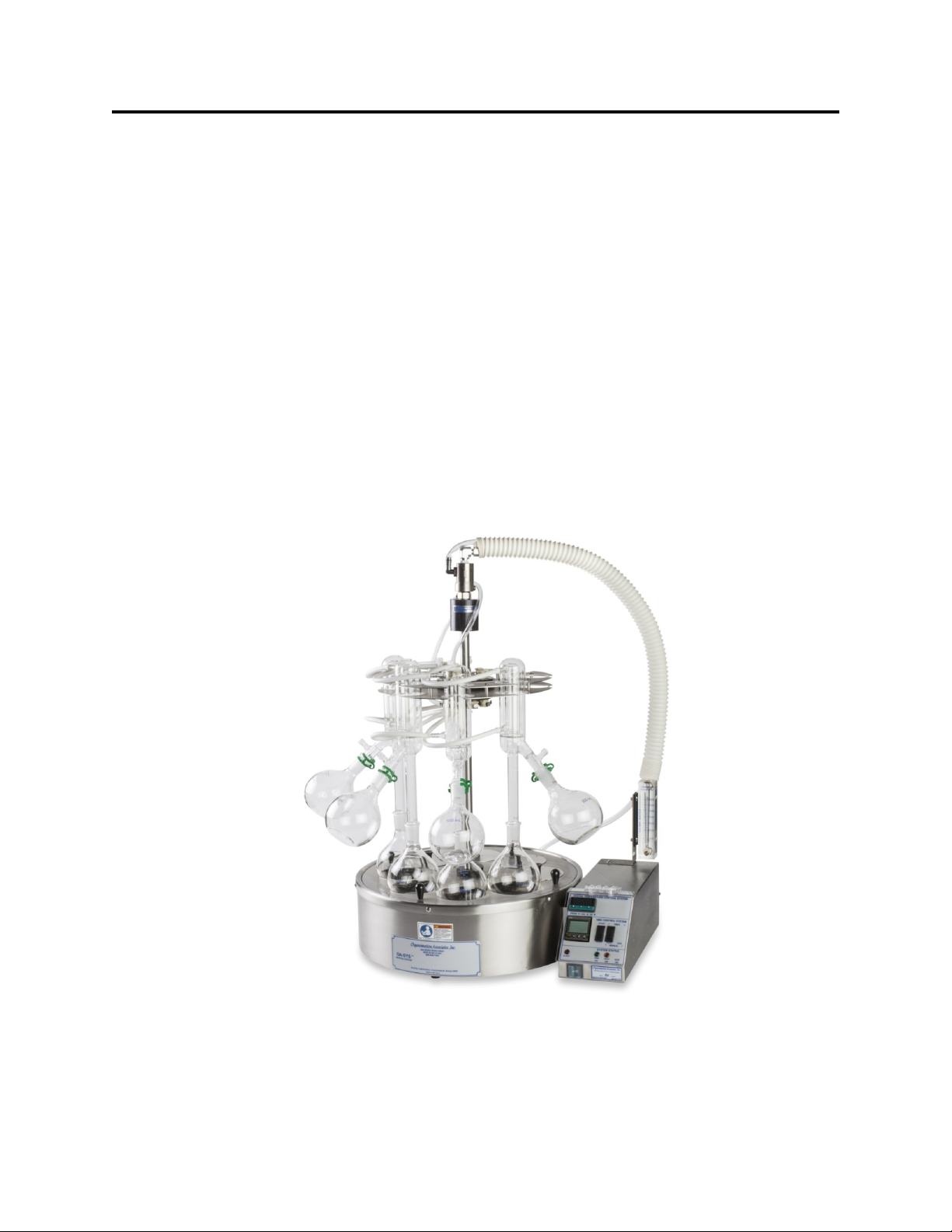
S-EVAP-RB TM
Items Shipped
Carefully check the contents of all cartons received for damage which may have occurred in
transit. Retain all cartons and packaging materials until all components have been checked
against the packing slip, the component list below, and the equipment has been assembled and
tested. Contact Organomation Associates Inc. immediately if any damage or discrepancies are
found.
Your shipment should contain one or more of the instruments and / or glass sets shown below.
Option codes are listed on the next page.
Instruments Only (Glassware Sold Separately)
8 Position S-EVAP, 4.5” deep x 12” Diameter Bath - 250 ML RB Flasks
10 Position S-EVAP, 4.5” deep x 16” Diameter Bath - 250 ML RB Flasks
8 Position S-EVAP, 4.5” deep x 16” Diameter Bath - 500 ML RB Flasks
Flow meter Assembly with Mounting Bracket & Tubing.
0-3500 CCM for condenser water supply.
OA-SYS Water Bath 1100W, Model 12060
OA-HEAT Water Bath 1400W, Models 12090, 12008
Thermometer 0 - 100º Celsius, 6” long, 4.5” deep baths (Optional)
Water Services Tube Assembly includes:
SS water inlet Tube 3/8” (mm) OD, PVC water outlet tube 1/2” (12mm) OD,
and Polypropylene extendable jacket.
Ball Driver, 5/32” x 9” Long.
Manual for all S-EVAP-RB models.
SS Cover disk assembly, includes: Hole covers (5 or 8, subject to Model), collar, and tear
drop handles, 3.0” hole size for 12” diameter and 3.875” hole size for 16” diameter bath.
Cat #
12060
12090
12008
P2121
B2110
B2104
NA1110
- - - -
V11437
- - - -
- - - -
S-EVAP and OA-HEAT are Trademarks of Organomation