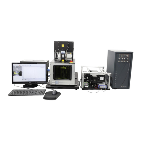
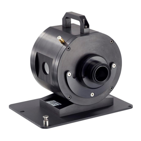
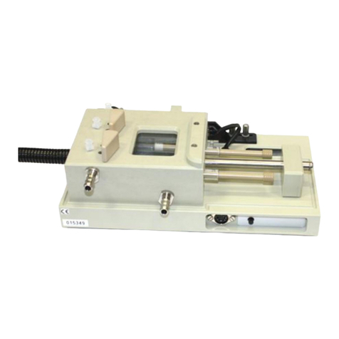
Applied Photophysics Chirascan LD User manual

User Manual
Chirascan Couette Cell LD Accessory
Applied Photophysics Limited
21 Mole Business Park
Leatherhead
Surrey
KT22 7BA
United Kingdom
Tel: +44 1372 386 537
Fax: +44 1372 386 477
Email: info@photophysics.com
Applied Photophysics, Inc.
100 Cummings Center
Suite 440-C
Beverly
MA 01915
United States
Tel: +1 978 473 7477
Email: info.usa@photophysics.com
www.photophysics.com

Document 4207Q258 V3.00 January 2018 Page 2 of 30
Chirascan Couette Cell LD Accessory User Manual
This document contains important safety information. Read this document and the
Chirascan V100 Spectrometer User Manual before attempting to install or use the
Couette Cell LD Accessory. Failure to do so could result in death or serious injury.

Document 4207Q258 V3.00 January 2018 Page 3 of 30
Chirascan Couette Cell LD Accessory User Manual
CONTENTS
CONTENTS........................................................................................................................................................3
USE OF THIS DOCUMENT ...............................................................................................................................4
HAZARD AND OTHER INDICATORS ...............................................................................................................5
ESSENTIAL SAFETY INFORMATION...............................................................................................................6
CHIRASCAN COUETTE CELL LD ACCESSORY INSTALLATION AND OPERATIONAL REQUIREMENTS 7
GLOSSARY........................................................................................................................................................8
1 INTRODUCTION.............................................................................................................................................9
2 PREPARATION.............................................................................................................................................12
2.1 Removing the installed accessories ...................................................................................................12
2.2 LD calibration......................................................................................................................................12
2.3 References..........................................................................................................................................16
3 THE COUETTE CELL LD ACCESSORY......................................................................................................17
3.1 Components of the Couette Cell LD Accessory .................................................................................17
3.2 Installing the Couette Cell LD Accessory............................................................................................18
3.2.1 Installing the accessory body ............................................................................................................ 18
3.2.2 Temperature control connections .................................................................................................... 19
3.3 The Couette cell..................................................................................................................................20
3.3.1 Components of the Couette cell ....................................................................................................... 20
3.3.2 Mounting the rotor assembly ........................................................................................................... 21
3.3.3 Loading the sample and mounting the stator ................................................................................... 22
3.3.4 Checking the sample ......................................................................................................................... 23
3.4 Making Linear Dichroism measurements using the accessory ..........................................................23
3.4.1 The Chirascan Pro-Data control software ......................................................................................... 23
3.4.2 The SmartMotor control software .................................................................................................... 23
3.4.3 The Command Pane .......................................................................................................................... 24
3.4.4 Taking a baseline. .............................................................................................................................. 25
3.5 Making circular dichroism measurements using the accessory .........................................................26
3.5.1 Making a CD measurement using the Couette cell ........................................................................... 26
3.5.2 Making a CD measurement using a rectangular cell ......................................................................... 26
3.6 Other experimental considerations.....................................................................................................27
3.7 Example: Calf thymus DNA ................................................................................................................28
3.8 Dismantling and cleaning....................................................................................................................29
3.9 References..........................................................................................................................................29
4 MAINTENANCE AND STORAGE .................................................................................................................30

Document 4207Q258 V3.00 January 2018 Page 4 of 30
Chirascan Couette Cell LD Accessory User Manual
USE OF THIS DOCUMENT
This document is intended to inform the operator of Applied Photophysics Couette Cell LD Accessory on its
design, installation and operation with a Chirascan V100 Spectrometer, and this document should be used in
conjunction with the User Manual applicable to the spectrometer. It is assumed that the user of this document
is familiar with the operation of the Chirascan spectrometer, and with Applied Photophysics Pro-Data software.
In particular it is assumed that the user is familiar with the hazards associated with the operation of the
spectrometer, and has read the hazard and other safety information contained in its User Manuals.
The information in this document is subject to change without notice and should not be construed as a
commitment by Applied Photophysics, who accept no responsibility for errors that may appear herein. This
document is believed to be complete and accurate at the time of publication, and in no event shall Applied
Photophysics be held responsible for incidental or consequential damages with or arising from the use of this
document.
COPYRIGHT 2018 APPLIED PHOTOPHYSICS LIMITED. ALL RIGHTS RESERVED. THIS DOCUMENT
OR PARTS THEREOF SHALL NOT BE REPRODUCED IN ANY FORM WITHOUT THE WRITTEN
PERMISSION OF THE PUBLISHER.
THE SOFTWARE PROVIDED WITH THE CHIRASCAN AND ITS ACCESSORIES (PRO-DATA CHIRASCAN,
PRO-DATA VIEWER, ETC.) IS THE PROPERTY OF APPLIED PHOTOPHYSICS LIMITED AND IS
SUPPLIED UNDER LICENSE. APPLIED PHOTOPHYSICS IS WILLING TO LICENSE THE SOFTWARE
ONLY UPON THE CONDITION THAT THE LICENSEE ACCEPTS ALL THE TERMS CONTAINED IN THE
LICENSE AGREEMENT. THESE INCLUDE THAT THE LICENSEE MAY NOT SELL, RENT, LOAN OR
OTHERWISE ENCUMBER OR TRANSFER LICENSED SOFTWARE IN WHOLE OR IN PART TO ANY
THIRD PARTY. FOR A FULL COPY OF THE LICENSE PLEASE CONTACT APPLIED PHOTOPHYSICS OR
SEE THE SOFTWARE INSTALLATION DISK.
Chirascan is a trademark of Applied Photophysics Limited.
All other trademarks or registered trademarks are the sole property of their respective owners

Document 4207Q258 V3.00 January 2018 Page 5 of 30
Chirascan Couette Cell LD Accessory User Manual
HAZARD AND OTHER INDICATORS
HAZARD INDICATORS USED IN THIS DOCUMENT
The sign to the left is used to indicate a hazardous situation, which, if not avoided, could result
in death or serious injury.
The sign to the left is used to indicate a hazardous situation, which, if not avoided, could result
in minor or moderate injury.
OTHER INFORMATORY INDICATORS USED IN THIS DOCUMENT
The sign to the left is used to indicate a situation which, if not avoided, could result in damage
to the instrument.
HAZARD INDICATORS USED ON THE SPECTROMETER OR ITS ACCESSORIES
Note that these hazard indicators may be either colored as below or as black and white.
The sign to the left is a general hazard indicator, indicating the presence of a hazard that is either
described by text accompanying the sign or in this User Manual.
The sign to the left is a high voltage hazard indicator.
The sign to the left is a flammable hazard indicator

Document 4207Q258 V3.00 January 2018 Page 6 of 30
Chirascan Couette Cell LD Accessory User Manual
ESSENTIAL SAFETY INFORMATION
MAKE SURE THAT YOU HAVE READ AND UNDERSTOOD ALL THE SAFETY INFORMATION CONTAINED
IN THIS DOCUMENT BEFORE ATTEMPTING TO INSTALL OR OPERATE COUETTE CELL LD
ACCESSORY. IF YOU HAVE ANY QUESTIONS REGARDING THE OPERATION OF THE ACCESSORY,
PLEASE CONTACT APPLIED PHOTOPHYSICS TECHNICAL SUPPORT AT THE ADDRESS SHOWN ON
THE FIRST PAGE OF THIS USER MANUAL.
OBSERVE ALL SAFETY LABELS AND NEVER ERASE OR REMOVE SAFETY LABELS.
PERFORMANCE OF INSTALLATION, OPERATION OR MAINTENANCE PROCEDURES OTHER THAN
THOSE DESCRIBED IN THIS USER MANUAL MAY RESULT IN A HAZARDOUS SITUATION AND WILL
VOID THE MANUFACTURERS WARRANTY.
The Chirascan spectrometer is powered by the mains electricity supply which can produce a
shock leading to serious injury or death. Do not connect or disconnect the instrument from the
mains supply unless the supply is powered off at source. Ensure all communications and
electrical connections are made before powering on the spectrometer. Exercise care during
operation and do not operate units with their covers removed. Operate the spectrometer using
only the cables provided. Never operate a spectrometer with damaged cables.
The Photomultiplier Tube (PMT) and Large Area Photodiode (LAAPD) detectors used with the
Chirascan spectrometers operate at high voltages and can produce a shock leading to serious
injury or death. Do not connect or disconnect the detector from the spectrometer unless the
spectrometer is powered off.
Do not allow any item, including any component of the alignment jig or the a to come into
contact with the front end of the detector while the detector is connected and powered up, as
this may cause an electrical short leading to serious injury to the user and damage to the
detector.
Although the main components of the accessory are temperature rated from 5°C to 95°C,
some of the standard fittings for the circulating water are only rated to 60°C, and could fail at
higher temperatures, causing injury to the user and damage to the accessory. The standard
operating range should be taken as 5°C to 60°C. Do not use the accessory at temperatures
outside this range unless the standard fittings have been replaced with high temperature
alternatives by Applied Photophysics.
If the water pressure of the circulator used for controlling the temperature is too high, the tubing
can be forced from the connectors within the spectrometer sample housing unit. Do not exceed
an input water pressure of 1.7 bar (24 p.s.i.).
Corrosive chemical and organic solvents can cause damage to the accessory body. Do not
allow corrosive fluids to come into contact with any part of the accessory body. Do not clean
the body with organic solvents. Use only a soft cloth and water or a mild detergent solution.

Document 4207Q258 V3.00 January 2018 Page 7 of 30
Chirascan Couette Cell LD Accessory User Manual
CHIRASCAN COUETTE CELL LD ACCESSORY INSTALLATION AND OPERATIONAL
REQUIREMENTS
Environmental and electrical requirements
The Couette Cell LD Accessory has no environmental requirements additional to those of the Chirascan
spectrometer. The accessory has a power unit that requires a separate mains electricity supply.
Bench space
The Couette Cell LD Accessory power supply has a footprint of about 260 x 260 mm and should stand to the
right of the spectrometer sample chamber.
Nitrogen purge gas
The Couette Cell LD Accessory has no purge gas requirements additional to those of the Chirascan
spectrometer.
Circulating water
For temperature control, the Couette Cell LD Accessory requires a circulating water flow rate of about 200 –
300 ml per minute. To achieve this, a pressure of approximately 0.2 –0.3 bar (3 to 4.5 p.s.i.) is needed. For
further information on suitable circulators, please contact the Applied Photophysics Technical Support
Department at the address given on the front of this User Manual.
Servicing
Servicing of the Couette Cell LD Accessory should only be undertaken by qualified personnel. If you are in any
doubt at all please contact the Applied Photophysics Technical Support Department at the address given on
the first page of this User Manual.

Document 4207Q258 V3.00 January 2018 Page 8 of 30
Chirascan Couette Cell LD Accessory User Manual
GLOSSARY
The following abbreviations may be found in this User Manual
CD Circular dichroism
LAAPD Large area avalanche photodiode
LD Linear dichroism
PMT Photomultiplier tube
rad s-1 radians per second, a measure of angular velocity.
rps revolutions per second, a measure of rotational speed
HYPERLINKS
This document contains hyperlinks between references (for example the Contents tables, or references to
Sections or Figures in the text), and sources. To follow a link, place the cursor over the reference and use
CTRL+click. Hyperlinks in the text are indicated by underlined blue font.
.

Document 4207Q258 V3.00 January 2018 Page 9 of 30
Chirascan Couette Cell LD Accessory User Manual
1 INTRODUCTION
The Chirascan High Shear Couette Cell LD Accessory is designed to be used with the Chirascan V100
Spectrometer. The accessory is shown in Figure 1.1.
Figure 1.1: The Applied Photophysics Couette Cell LD accessory
The accessory is usually used for linear dichroism (LD) measurements. Linear dichroism is the difference in
the absorbance of light polarized parallel and perpendicular to an orientation axis (Equation 1.1)
A = A|| - A1.1
where A is the absorbance of the linearly polarized light, and the subscripts || and indicate parallel and
perpendicular respectively. For a sample to have non-zero linear dichroism it must be anisotropic; the
anisotropy may be intrinsic, as in liquid crystals for example, or it may be induced, for example by stretching a
polymer film, by the application of an electrical field or by alignment of deformation in a shear field.
The accessory uses a Couette cell to generate a shear field. The sample is contained in the annular gap
between two concentric quartz cylinders, the outer of which, the rotor, is rotated about its cylindrical axis, while
the inner, the stator, is stationary. This arrangement is named after its originator, Maurice Couette.
A shearing motion is shown in two dimensions in Figure 1.2, where the blue rectangle, of height y, deforms to
the yellow parallelogram, with the top edge of the rectangle moving by a distance x in the direction of the
arrow. The shear strain, , is then defined as x/y, and the shear rate, γ, as d/dt, in the limit as y goes to zero
(the overdot is Isaac Newton’s original symbol for the time derivative, and is still universally used by
rheologists). The strain is therefore dimensionless, and the shear rate has dimensions of reciprocal time (s-1
in the S.I. system)

Document 4207Q258 V3.00 January 2018 Page 10 of 30
Chirascan Couette Cell LD Accessory User Manual
Figure 1.2: Two-dimensional representation of a shearing motion
Shearing can cause large particles in the liquid to align or deform. For example rigid, rod-like, particles such
as carbon nanotubes and glass fibers, will align, whereas vesicles, micelles and flexible polymers will deform
from their equilibrium conformations, extending in the direction of shear. Linear dichroism is then used to
determine the direction of net electron transfer in an absorbed chromophore relative to the shear direction, and
thereby to the alignment direction of the absorbing species or membrane.
A schematic of the Couette cell used in the accessory is shown in Figure 1.3. In the figure, the sample is shown
in blue, the light path in violet. The black arrows indicate the standard direction of rotation of the outer cylinder,
which is anticlockwise (counterclockwise) when viewed from above.
Figure 1.3: Schematic of the Couette cell; top view is shown on the right with the light path in violet
The sample is therefore sheared between the two cylinders in the cell, at a rate proportional to the angular
velocity of the rotor, . The angular velocity is measured in radians per second (rad s-1), and is equal to 2x
the rotational speed in revolutions per second (rps). The shear rate is measured in reciprocal seconds (s-1
1/s).
The diameter of the rotor in the cell is 9.55 mm, and of the stator is 9.05 mm; the annular gap is thus 0.25 mm,
but note that since the light passes though the sample twice, the pathlength is 0.5 mm (these dimensions may
vary slightly, but will always be known precisely).
Outer cylinder
(rotor)
Inner cylinder
(stator)
Sample
Outer cylinder
(rotor)
Inner cylinder
(stator)
Sample
Light path

Document 4207Q258 V3.00 January 2018 Page 11 of 30
Chirascan Couette Cell LD Accessory User Manual
Due to the curvature of the cylindrical surfaces, the shear rate, γ, varies slightly across the gap [1]. If the
sample viscosity, , is independent of the shear rate, as it is likely to be for the dilute materials normally used
with the Couette cell, then the shear rate at the inner cylinder is given by:
γi= 2 Ro2/ (Ro2–Ri2)
and at the outer cylinder is given by:
γ o= 2 Ri2/ (Ro2–Ri2)
where is the angular velocity in radians per second (rad s-1), R is the radius, and the subscripts i and o refer
to the inner and outer cylinders respectively [1]. Thus there is a difference in shear rate between the outer and
inner cylinders of a factor of (Ro/Ri)2or about 11%. This difference is small enough to allow the approximation:
γ = Ro/ (Ro–Ri)
This expression is used in the accessory software to calculate the shear rate. It is central to the design of the
accessory that the shear rate is as homogenous as possible, so that all parts of the sample are experiencing
almost the same shear rate, and the error introduced by using a single value shear rate is minimized.
A coincidence! The factor Ro/ (Ro–Ri) is equal to 19.1 for a 9.55 mm diameter rotor and a 0.25 mm gap.
Since the conversion from revolutions per second (rps) to radians per second (rad s-1) is to multiply by 2, the
conversion factor from rps to shear rate is 19.1 x 2which equals almost exactly 120. The apparent neatness
of this number is entirely coincidental on the dimensions used for the Couette cell (to put it another way, 30/9.55
is a very good approximation to ).
Note that the absorbance can be measured simultaneously with the linear dichroism, but that the circular
dichroism (CD) cannot be measured on a system with a significant linear dichroism component, as the
calculation of the CD requires that there is no LD or birefringence component to the response.
1, R.W. Whorlow, “Rheological Techniques”,2nd edition, Ellis Horwood, 1992, p103.
For more information on linear dichroism and its measurement, see B. Norden, A. Rodger and T. Dafforn
“Linear Dichroism and Circular Dichroism”, 2nd edition, RSC Publishing, 2010

Document 4207Q258 V3.00 January 2018 Page 12 of 30
Chirascan Couette Cell LD Accessory User Manual
2 PREPARATION
2.1 Removing the installed accessories
Remove any installed accessory, including all detectors. For instructions on removal of an accessory, see the
relevant user manual.
The Photomultiplier Tube (PMT) and Large Area Photodiode (LAAPD) detectors used with the
Chirascan spectrometers operate at high voltages and can produce a shock leading to serious
injury or death. Do not connect or disconnect the detector from the spectrometer unless the
spectrometer is powered off.
After the accessories have been removed, the interior of the spectrometer sample chamber should appear as
in Figure 2.1.
Figure 2.1: The interior of the sample chamber after removal of accessories
2.2 LD calibration
The accessory needs to be calibrated before being used for linear dichroism measurements. If the accessory
is supplied with a new spectrometer, then the calibration will have been carried out by the Applied Photophysics
Production Department as part of the build and testing process. If it is supplied as an upgrade to an existing
instrument, then the calibration can be carried out by the user or by an Applied Photophysics engineer.
The principle of calibration is described by Norden [1]. An angled quartz fused silica plate is used as an
adjustable polarizing element. The LD standard used by APL is a 1 mm fused silica plate aligned at 30° to the
incident light. The ideal linear dichroism value for the 30° plate at 250 nm is A = 0.03006.
Fluorescence port
locking ring

Document 4207Q258 V3.00 January 2018 Page 13 of 30
Chirascan Couette Cell LD Accessory User Manual
Figure 2.2: The linear dichroism alignment jig
The calibration jig is shown in Figure 2.2. The jig consists of the mounting assembly and the removable holder
for the silica plate (Figure 2.3). The plate holder can be mounted in the assembly in five positions: vertically up
or down, horizontally left or right, and the neutral position.
Figure 2.3: The holder for the silica plate
To install the alignment jig, remove any installed accessories (Section 2.1), including the detector, although
not the locking ring.
Do not allow any item, including any component of the alignment jig or the accessory to come
into contact with the front end of the detector while the detector is connected and powered up,
as this may cause an electrical short leading to serious injury to the user and damage to the
detector.
Install the alignment jig as in Figure 2.4. Place the mounting plate of the jig over the support plate in the sample
chamber. The plate seats down with the holes at the front left and rear right locating over the corresponding
pegs on the support plate. When the plate is seated down, secure it in place by tightening the two captive
thumbscrews positioned at the right front and left rear of the mounting plate. Reinstall the detector, ensuring
that the tip of the detector is at least 35 mm from the plate holder (the shoulder of the detector should be flush
with the front of the locking ring).

Document 4207Q258 V3.00 January 2018 Page 14 of 30
Chirascan Couette Cell LD Accessory User Manual
Figure 2.4: The alignment jig mounted in the spectrometer sample chamber
Select Linear Dichroism from the drop-down list in the Signal panel of the Chirascan control page (Figure
2.5).
Figure 2.5: The Signal panel for Linear Dichroism

Document 4207Q258 V3.00 January 2018 Page 15 of 30
Chirascan Couette Cell LD Accessory User Manual
Enter the settings as in Table 2.1.
Signal
Linear dichroism
Mode
Spectrum
Wavelength range
700 to 200 nm
Wavelength step
5 nm
Bandwidth
1 nm
Time per point
1 second
Table 2.1: spectrometer settings for determining the LD calibration factor
With the reference plate holder in the neutral position (Figure 2.6), name the spectrum appropriately, e.g. “LD
neutral” and click Acquire to run an LD spectrum. Move the plate holder to the vertically up position: the
handle should be pointing up, and the short peg seated in the groove. Name the spectrum e.g. “LD vertical
up”, run a spectrum and repeat for the other three positions.
Figure 2.6: The reference plate holder in the neutral, vertical up, and horizontal right positions (left to right)
In the Pro-Data Viewer software, plot the five spectra. The two vertical spectra should be similar to each other
and of opposite sign to the two horizontal spectra, which should also be similar to each other.
Average the two vertical spectra and the two horizontal spectra, set the neutral spectrum as the baseline and
subtract the baseline from the two averaged spectra. One of these spectra should be positive and the other
negative. Multiply the negative spectrum by minus 1 using the Pro-Data Viewer software to convert it to positive
and average the two spectra which are now positive. The accepted absolute LD value at 250 nm is 0.03006,
and by convention the orientation direction is taken as being the parallel direction.
The LD calibration factor used to calculate the linear dichroism is set in the configuration file LDConfig.conf
in the folder C:\Program Files (x86)\Applied Photophysics\Chirascan\Config
The file can be adjusted using a text editor such as Microsoft Notepad (Figure 2.7). The calibration factor is
listed as CalFac and is shown circled in the figure. You will need administrator rights to adjust the factor.

Document 4207Q258 V3.00 January 2018 Page 16 of 30
Chirascan Couette Cell LD Accessory User Manual
Figure 2.7: the LDConf.conf file
If the measured absolute value of the LD at 250 nm is not 0.03006 ± 0.0003 (i.e. within 1% of the accepted
value), the calibration factor should be adjusted. The new calibration factor is calculated as:
New calibration factor = present calibration factor x 0.03006 / measured LD value.
By convention the parallel direction for the Couette cell is taken as being the flow direction, i.e. the horizontal
direction of the alignment jig. If the LD calibration factor gives the correct absolute value, but the incorrect sign,
change the sign of the calibration factor.
Input the new factor and save the file.
2.3 References
1, B. Norden and S. Seth, Appl. Spectroscopy, 39 (1985) 647-655.

Document 4207Q258 V3.00 January 2018 Page 17 of 30
Chirascan Couette Cell LD Accessory User Manual
3 THE COUETTE CELL LD ACCESSORY
3.1 Components of the Couette Cell LD Accessory
The main components of the accessory are shown in Figure 3.1. In the figure the light inlet port is to the front.
Figure 3.1: Components of the Couette Cell LD accessory
The accessory consists of the main body and a demountable Couette cell. The Couette cell consists of a rotor
and a stator assembly. The rotor assembly is made up of the quartz cylinder, with a removable PEEK plug and
a PEEK centralizing bush. The stator assembly is made up the quartz cylinder and a holder assembly with a
knurled locking collar.
The accessory is provided with a viewing window so that the sample can be seen during and after loading, to
ensure that filling is correct and the sample is free from bubbles. The sample is illuminated by an LED controlled
by a rocker switch, and the light is reflected upwards by an angled mirror so that the sample can be seen.
If required, the temperature of the accessory can be controlled by circulating water that passes through a jacket
surrounding the cell. A temperature probe is embedded within the assembly a short thermal distance from the
rotor, although not in physical contact with it (the probe is read only, and does not form part of the temperature
control loop). The temperature should be set directly on the circulator.
Stator locking collar
Rotor centralizing bush
Viewing window
Stator holder assembly
Light inlet port
Viewing light rocker switch
Motor
LED cover
Mounting plate
LED connection
Motor connection
Temperature
probe connection

Document 4207Q258 V3.00 January 2018 Page 18 of 30
Chirascan Couette Cell LD Accessory User Manual
3.2 Installing the Couette Cell LD Accessory
3.2.1 Installing the accessory body
Before the accessory is installed, the standard bulkhead blanking plate should be removed from the Chirascan
sample chamber and replaced with the plate fitted with two power connectors (Figure 3.2: note that in the
figure the blanking plate also contains a fitting for the Chirascan Titration accessory). The plate is held in
position from inside the sample chamber by four caphead screws.
Figure 3.2: The blanking plate mounted on the Chirascan sample chamber
The accessory stands on a mounting plate which locates on a support plate within the Chirascan sample
chamber. Place the mounting plate of the accessory over the support plate in the sample chamber. The plate
seats down with the holes at the front left and rear right locating over the corresponding pegs on the support
plate. When the plate is seated down, secure it in place by tightening the two captive thumbscrews positioned
at the right front and left rear of the mounting plate.
The detector can now be re-installed. The snout of the detector slides into the cowling which rests against the
accessory body. The cowling has a gas purge inlet, which connects to the ‘Y’ connector at the rear of the unit,
using the additional steel tubing provided. The extendable threaded spacer fits between the light inlet port and
the accessory. The spacer has O-rings at each end: the narrower end goes towards the accessory assembly.
Connect the Legris type connectors for the circulating water by pushing home the male on the accessory to
the female on the sample chamber.
Ensuring that the accessory electronics box is not powered up, connect the two circular electrical connectors.
Note that the smaller, 3-pin connector serves the LED and the larger, 8-pin connector serves the motor.
When the accessory is fully installed without the Couette cell, the interior of the spectrometer sample chamber
should appear as in Figure 3.3.
Blanking plate

Document 4207Q258 V3.00 January 2018 Page 19 of 30
Chirascan Couette Cell LD Accessory User Manual
Figure 3.3: Interior of the sample chamber with the accessory in place
3.2.2 Temperature control connections
Although the main components of the accessory are temperature rated from 5°C to 95°C,
some of the standard fittings for the circulating water are only rated to 60°C, and could fail at
higher temperatures, causing injury to the user and damage to the accessory. The standard
operating range should be taken as 5°C to 60°C. Do not use the accessory at temperatures
outside this range unless the standard fittings have been replaced with high temperature
alternatives by Applied Photophysics.
There is no direct temperature control on the Couette Cell Accessory. However, the temperature can be
controlled by an external a water circulator with a flow rate of about 200 –300 ml per minute. To achieve this,
a pressure of approximately 0.2 –0.3 bar (3 to 4.5 p.s.i.) is needed.
If the water pressure of the circulator used for controlling the temperature is too high, the tubing
can be forced from the connectors within the spectrometer sample housing unit. Do not exceed
an input water pressure of 1.7 bar (24 p.s.i.).
The circulating water connections are to the male Legris type fittings on the tubing at the rear of the sample
chamber (Figure 3.4).

Document 4207Q258 V3.00 January 2018 Page 20 of 30
Chirascan Couette Cell LD Accessory User Manual
Figure 3.4: Circulating water connections at the rear of the sample chamber
3.3 The Couette cell
3.3.1 Components of the Couette cell
The demountable Couette cell consists of a rotor assembly and a stator assembly. The rotor assembly is made
up of the quartz outer cylinder, a removable PEEK plug and a PEEK centralizing bush, as shown in Figure 3.5
Figure 3.5: The rotor assembly dismantled (left) and assembled (right)
Centralizing
bush
Cylinder
Plug
Circulating
water
connections
Table of contents
Other Applied Photophysics Laboratory Equipment manuals
Popular Laboratory Equipment manuals by other brands

Alecto
Alecto BF55 instruction manual

Scientific Industries
Scientific Industries MULTIPLATE GENIE SI-4100 operating instructions

MELAG
MELAG Vacuklav 24 B+ Technical description

Oxford Instruments
Oxford Instruments ANDOR ZL41 Cell user guide

Hamilton Bahl
Hamilton Bahl VanGuard v6500 Operator's manual

Tuttnauer
Tuttnauer LABSCI 15L Operation and maintenance manual