Applied Photophysics RX2000 User manual

User Manual
RX2000
Rapid Mixing Stopped Flow Unit
April 2013
Document 4400Q902 version 1.02

Document 4400Q902 version 1.02 Page 2 of 18
RX2000 User Manual
This page is intentionally left blank

Document 4400Q902 version 1.02 Page 3 of 18
RX2000 User Manual
This document contains important safety information. Read this document before
attempting to install or use the RX2000. Failure to do so could result in injury to the
user.

Document 4400Q902 version 1.02 Page 4 of 18
RX2000 User Manual
USE OF THIS DOCUMENT
This document is intended to inform the operator of Applied Photophysics’ RX2000 Rapid-Mixing Stopped-Flow
Unit on its design, installation and operation. The information in this document is subject to change without notice
and should not be construed as a commitment by Applied Photophysics, who accept no responsibility for errors
that may appear herein. This document is believed to be complete and accurate at the time of publication, and in
no event shall Applied Photophysics be held responsible for incidental or consequential damages with or arising
from the use of this document.
COPYRIGHT 2013 APPLIED PHOTOPHYSICS LTD. ALL RIGHTS RESERVED. THIS DOCUMENT OR
PARTS THEREOF SHALL NOT BE REPRODUCED IN ANY FORM WITHOUT THE WRITTEN PERMISSION
OF THE PUBLISHER.
RX2000™is a trademark of Applied Photophysics Ltd.
Norton™ is a trademark of Symantec Corporation or its affiliates in the United States and other countries.
McAfee® is a registered trademark of McAfee, Inc. in the United States and other countries.
Sophos® is a registered trademark of Sophos Plc and Sophos Group.
Kloehn® is a registered trademark of Kloehn Inc.
All other trademarks or registered trademarks are the sole property of their respective owners.

Document 4400Q902 version 1.02 Page 5 of 18
RX2000 User Manual
HAZARD AND OTHER INDICATORS
HAZARD INDICATORS USED IN THIS DOCUMENT
The sign to the left is used to indicate a hazardous situation, which, if not avoided, could result in
minor or moderate injury.
OTHER INFORMATORY INDICATORS USED IN THIS DOCUMENT
The sign to the left is used to indicate a situation which, if not avoided, could result in damage to
the instrument.
HAZARD INDICATORS USED ON THE RX2000
Note that this hazard indicator may be either coloured as below or as black and white.
The sign to the left is a general hazard indicator, indicating the presence of a hazard that is either
described by text accompanying the sign or in this User Manual.

Document 4400Q902 version 1.02 Page 6 of 18
RX2000 User Manual
ESSENTIAL SAFETY INFORMATION
MAKE SURE THAT YOU HAVE READ AND UNDERSTAND ALL THE SAFETY INFORMATION CONTAINED
IN THIS DOCUMENT BEFORE ATTEMPTING TO OPERATE THE RX2000. IF YOU HAVE ANY QUESTIONS
REGARDING THE OPERATION OF THE RX2000, PLEASE CONTACT APL TECHNICAL SUPPORT SECTION
AT THE ADDRESS SHOWN ON THE FIRST PAGE OF THIS DOCUMENT.
OBSERVE ALL SAFETY LABELS AND NEVER ERASE OR REMOVE SAFETY LABELS.
PERFORMANCE OF INSTALLATION, OPERATION OR MAINTENANCE PROCEDURES OTHER THAN
THOSE DESCRIBED IN THIS USER MANUAL MAY RESULT IN A HAZARDOUS SITUATION AND WILL VOID
THE MANUFACTURERS WARRANTY.
The RX2000 pneumatic accessory uses compressed gas to drive the drive syringes and could
trap hands or clothing, causing injury to the user. Keep hands and clothing clear when
performing a drive using the accessory.
Corrosive chemical and organic solvents can cause damage to the RX2000. Do not allow
corrosive fluids to come into contact with any part of the spectrometer. Do not clean the
spectrometer with organic solvents. Use only a soft cloth and water or a mild detergent solution.

Document 4400Q902 version 1.02 Page 7 of 18
RX2000 User Manual
RX2000 INSTALLATION AND OPERATIONAL REQUIREMENTS
Environmental requirements
The RX2000 is best installed in a safe position, in a clean, air-conditioned laboratory environment.
Operating conditions
Temperature: ±2oC of a fixed temperature in the range 18oC to 26oC.
Humidity 20% to 80% non-condensing
Storage conditions
Temperature -20°C to +50°C:
Humidity: 5% to 80% non-condensing
Bench space
The RX2000 requires a bench space of
Length x depth x height: 0.7 x 0.3 x 0.2 metres
alongside the spectrometer with which it is used.
A sturdy, stable, vibration-free work surface is recommended.
Fluid circulator unit
The RX2000 can be used with or without temperature control. Temperature control is provided by a standard
laboratory temperature controlled fluid circulator.
Servicing
Servicing of the RX2000 should only be undertaken by qualified personnel. If you are in any doubt at all please
contact the Applied Photophysics Technical Support Department at the address given on the front of this User
Manual

Document 4400Q902 version 1.02 Page 8 of 18
RX2000 User Manual
CONTENTS
USE OF THIS DOCUMENT.......................................................................................................................................4
HAZARD AND OTHER INDICATORS.......................................................................................................................5
ESSENTIAL SAFETY INFORMATION......................................................................................................................6
RX2000 INSTALLATION AND OPERATIONAL REQUIREMENTS..........................................................................7
CONTENTS ...............................................................................................................................................................8
FIGURES...................................................................................................................................................................8
1 INTRODUCTION ....................................................................................................................................................9
2 HARDWARE.........................................................................................................................................................10
2.1 Basic layout................................................................................................................................................10
2.2 The drive syringes......................................................................................................................................11
2.3 Reagent control valves...............................................................................................................................11
2.4 Waste control valve....................................................................................................................................12
2.5 The observation cell...................................................................................................................................13
2.6 Accessories................................................................................................................................................13
2.7 RX2000 specifications................................................................................................................................13
3 OPERATION.........................................................................................................................................................14
3.1 Instrument set-up .......................................................................................................................................14
3.1.1 Positioning the mixing unit and the DuoCell ............................................................................................. 14
3.1.2 Temperature control.................................................................................................................................. 14
3.1.3 Trigger signal.............................................................................................................................................. 14
3.2 Operation using the manual drive..............................................................................................................14
3.3 Operation using the pneumatic drive accessory........................................................................................15
3.4 Operation using the anaerobic accessory..................................................................................................16
3.4.1 Mounting the anaerobic accessory............................................................................................................ 16
3.4.2 Anaerobic operation .................................................................................................................................. 16
3.5 Operation using ratio mixing ......................................................................................................................17
3.6 Changing the drive syringe. .......................................................................................................................17
3.7 Selected test reactions...............................................................................................................................17
3.7.1 Formation of Iron (III) Thiocyante.............................................................................................................. 17
3.7.2 Fluorescence test reaction......................................................................................................................... 18
FIGURES
Figure 1.1: the RX2000.............................................................................................................................................9
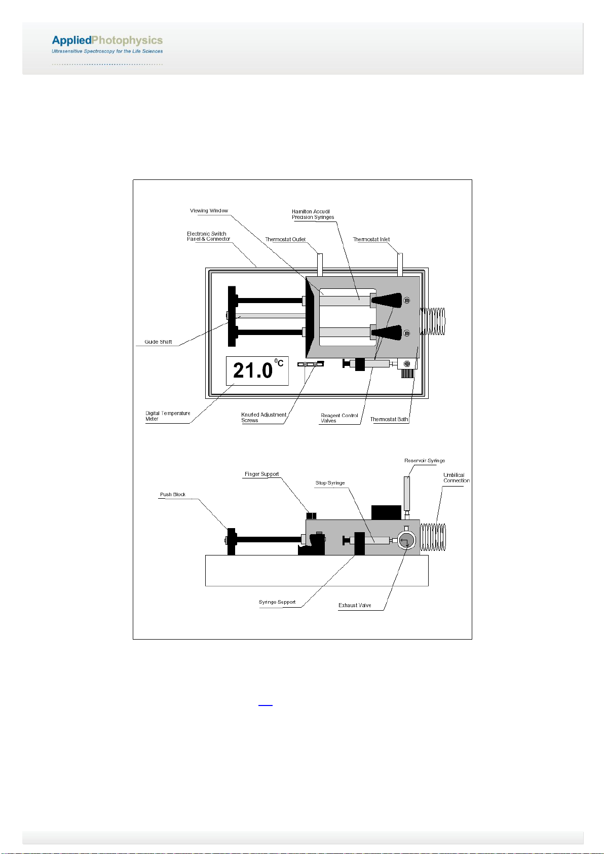
Figure 2.1: schematic of the RX2000 .....................................................................................................................10
Figure 2.2: the valve positions in the Load (left) and Drive (right) positions...........................................................11
Figure 2.3: flow line closed (left) and open to waste reservoir (right).....................................................................12
Figure 2.4: flow line in its normal drive position (left) and normal empty position (right)........................................12

Document 4400Q902 version 1.02 Page 9 of 18
RX2000 User Manual
1 INTRODUCTION
Figure 1.1: the RX2000
The RX2000, shown in Figure 1.1, is a high performance stopped-flow unit that enables your existing UV-visible
spectrometer, fluorimeter or circular dichroism (CD) spectrometer to be used to follow reactions that are at least
a thousand times faster than those accessible manually. With a dead-time of only 8 ms, first order reactions with
rates in excess of 200 s-1 can be followed.
The RX2000 is easily the most accomplished device of its type, making use of the latest advances in stopped-
flow design, combined with the simplicity, robustness and reliability of high quality instrument engineering. In one
action the RX2000 mixes two reactants, fills a sample cell, stops the flow and simultaneously provides an output
trigger. Its dual pathlength micro-volume cell employs the latest silica fusion technology to give the highest
possible optical efficiency and specification. All crucial sample flow circuit surfaces are biocompatible and
chemically inert. In addition, carefully selected materials are used throughout to protect the instrument from
aggressive chemicals. The entire flow circuit and the drive syringes themselves are located within a
thermostatable bath for accurate sample temperature control.
The stopped-flow technique for the rapid mixing of chemical reagents has gained widespread acceptance as
being a most useful and versatile method for obtaining reaction rate information. After the two reagents are
mixed, the course of their reaction together can be followed in conjunction with single beam UV-visible
absorption or fluorescence spectrometry as appropriate, using the optical absorption or emission properties of
either the initial reagents, or a product or a reaction intermediate. Changes in light scattering within the reaction
cell provide another measurement method. The technique finds applications in chemistry (redox reactions, metal-
ligand complexes, solvation, dye binding etc.), biochemistry (enzyme kinetics, electron and proton reactions,
binding of poisons to biologically important molecules, calcium and sodium ion interactions, protein binding,
enzyme conformation and denaturation studies) and biophysics (cell membrane studies, osmotic swelling,
oxygen uptake and release by red blood cells).
This User Manual gives comprehensive information about how to configure and operate the RX2000 Rapid
Mixing Stopped-Flow Unit.

Document 4400Q902 version 1.02 Page 10 of 18
RX2000 User Manual
2 HARDWARE
This Chapter describes the RX2000 hardware, covering the basic layout and main components of the accessory.
2.1 Basic layout
Figure 2.1: schematic of the RX2000
A schematic of the RX2000 is shown in Figure 2.1. The unit is designed to be compact and easy to use, allowing
stopped-flow measurements to be obtained with UV-visible spectrometers, fluorimeters and CD polarimeters with
the minimum amount of setting-up. It comprises a base in which the electronics, battery and LCD temperature
display panel are located. Attached to the top of the base is a reagent handling system with thermostat bath and
this is connected to a specialised cuvette via an umbilical. The sealed thermostat bath incorporates a window

Document 4400Q902 version 1.02 Page 11 of 18
RX2000 User Manual
which allows the drive syringes to be checked for the presence of air bubbles during filling and also to provide
visual assistance when making a syringe change (i.e. when fitting a different volume syringe).
2.2 The drive syringes
The drive syringes are brought outside the thermostat bath via a rubber grommet that has a double sealing edge.
This seal allows the user to readily interchange syringes of different diameters (volumes of 0.1 ml to 2.5 ml) with
the only proviso being that the thermostat bath should first be emptied.
The RX2000 uses three specially designed flow distribution valves, two of which are used to load the drive
syringes and the third to control the removal of waste solution from the flow line. The two drive syringes have
screw thread location whereas the reservoir, stopping and waste syringes use Luer location. The displacement of
the stopping syringe piston is controlled by an adjustable stop bar on which is mounted the trigger microswitch. A
smooth action push block with a stainless steel guide allows the contents of the drive syringes to be driven into
the flowline with consistent performance.
2.3 Reagent control valves
A schematic of the valve positions for loading the drive syringes and for a stopped-flow drive is shown in Figure
2.2.
Figure 2.2: the valve positions in the Load (left) and Drive (right) positions

Document 4400Q902 version 1.02 Page 12 of 18
RX2000 User Manual
2.4 Waste control valve
Figure 2.3 shows the waste control valve with the flow line closed, and with the flow line open to the waste
reservoir, as used for flushing. Figure 2.4 shows the flow line in the normal drive position, open to the stopping
syringe, and the normal empty position, open to the stopping syringe and waste reservoir.
Flow line closed Flow line open to waste reservoir,
used when flushing
Figure 2.3: flow line closed (left) and open to waste reservoir (right)
Flow line in its normal drive position, Flow line in its normal empty position,
open to stopping syringe open to stopping syringe and waste
reservoir
Figure 2.4: flow line in its normal drive position (left) and normal empty position (right)

Document 4400Q902 version 1.02 Page 13 of 18
RX2000 User Manual
2.5 The observation cell
The observation cell has the same external dimensions of standard 10 mm x 10 mm spectrometer cuvette, but is
specially designed with an integral mixer and orthogonal viewing ports which allow use of either 2 mm or 10 mm
pathlengths. The observation cell is connected to the drive syringes via the flow distribution valves using small
diameter FEP tubing.
The two supply lines and one return line together with a thermostating tube are all encased in an umbilical which
is corrugated for extra strength and flexibility. Two ports allow the thermostat bath to be connected to an external
constant temperature circulator. The inlet port (i.e. the lower of the two ports) is connected to a tube which runs
the full length of the umbilical. (The umbilical is an extension of the thermostat bath so that reagents are
thermostatted all the way to the observation cell). The return flow is contained within the umbilical case which
brings the thermostat medium back to the bath. The temperature of the thermostat medium is displayed on a
LCD.
2.6 Accessories
The RX2000 Stopped-Flow Mixing Accessory can be upgraded with a pneumatic drive attachment, which may
be used as required to provide powerful and reproducible stopped-flow drives.
An optional anaerobic accessory is available to facilitate the rigorous exclusion of oxygen from the flow circuit if
desired.
2.7 RX2000 specifications
DuoCell: Purpose designed micro-cell fitted with four observation windows.
Cell material: Silica (cell body and windows).
Flow circuit: Chemically inert (silica, glass and fluoro-carbon).
Optical axis: 15 mm above the cuvette base.
Mixer: An efficient twin-jet mixer is an integral part of the DuoCell.
Pathlength: Dual pathlength, 10 mm and 2 mm.
Flourescence: Large area window, 40 mm²
Volume: Observation volume is 60 µL
Volume per shot: From 120 µL per reactant.
Drive syringe: 2.5 ml Kloehn.
Mixing ratio: 1:1 as standard but other ratios can be obtained by substituting alternative syringes.
Drive: Manual or Pneumatic (optional extra).
Temperature range: 4° to 60°C
Display: LCD display of temperature with 0.1°C precision.
Trigger output: TTL, open collector and switch contact are provided.
Power supply: 9 volt battery (type PP3 or equivalent).
TRIGGER O/P: 5 pin DIN socket
pin 1 - open collector
pin 2 - ground (0 volts)
pin 3 - +5 volts, 1 ms duration (TTL)
pin 4 - microswitch contact

Document 4400Q902 version 1.02 Page 14 of 18
RX2000 User Manual
3 OPERATION
3.1 Instrument set-up
3.1.1 Positioning the mixing unit and the DuoCell
It is important that the RX2000 mixing unit is placed on a firm horizontal surface next to the spectrometer. Such
an arrangement will facilitate making a smooth drive and avoid placing strain on the DuoCell assembly.
Before operating the RX2000 make sure that the DuoCell is correctly positioned and secured in the cell holder.
Position the DuoCell in the spectrometer cuvette holder with the correct orientation for the desired pathlength (2
or 10 mm depending on orientation).
3.1.2 Temperature control
If constant temperature operation is required, first fill the thermostat bath with water (or whatever medium is to be
circulated) and then connect the inlet and outlet ports to a constant temperature laboratory circulator (the inlet
port is the one located closer to the base).
The temperature of the RX2000 is set by the fluid circulator. For guidance on the use of the circulator, see the
User Manuals provided by the supplier.
To display the temperature of the RX2000 bath, press the ON button.
3.1.3 Trigger signal
At the end of a stopped-flow drive, the stopping syringe piston causes the trigger microswitch contacts to close
and this is used to trigger data acquisition by the spectrometer. The trigger cable should be connected to the DIN
socket on the RX2000 and the GP-IO connector on the spectrometer. It will be necessary to activate external
triggering of the spectrometer in the control software before using the RX2000.
3.2 Operation using the manual drive
The following step-by-step procedure describes the use of the syringes and the various valves during reagent
loading, flowline flushing and stopped-flow drives.
1. Attach the waste reservoir syringe (complete with piston) to the Luer receptacle on the valve adjacent to
the stopping syringe.
2. The reservoir syringes can be used with or without pistons as preferred. Generally it is more convenient
to fit the barrels of the reservoir syringes to the reagent inlet ports with the pistons removed.
3. Set the main valves to the loading position (i.e. with each valve top pointing towards the left outside edge
of the thermostat bath) and push the drive syringe pistons fully forward.
4. Set the exhaust valve to the fully closed position - indicator arrows pointing downwards and to the right
(i.e. away from the stopping syringe and waste reservoir syringe).
5. Pour the appropriate reagents into the reservoirs.
6. Load the drive syringes by pulling back the drive syringe pistons.
7. Set the main valves to the drive position (i.e. with each valve top in line with its drive syringe).
8. Set the exhaust valve open to the waste reservoir syringe - indicator arrows pointing upwards and to the
right.
9. Push the drive syringe pistons fully forward to flush out the flow lines.
10. Check to see if any air bubbles are trapped in the drive syringe or in the DuoCell and repeat the flushing
procedure if necessary.

Document 4400Q902 version 1.02 Page 15 of 18
RX2000 User Manual
11. Set the main valves to the loading position and reload the drive syringes with reagents.
12. Set the exhaust valve to open the stopping syringe to the waste reservoir, the indicator arrows should
point upwards and to the left, and push the stopping syringe piston fully forward.
13. Set the exhaust valve to connect the stopping syringe to the main flow line - indicator arrows should
point downwards and to the left.
14. Set the position of the stopping-bar and microswitch, located adjacent to the stopping syringe, according
to the total reagent volume required on each drive (i.e. between 0.3 ml and 0.5 ml).
15. Set the main valves to the drive position and push the drive bar firmly but smoothly.
16. Return the main valves to the loading position so as to isolate the drive syringes from the flow line (this
ensures that previously mixed solution cannot be passed back up the flowline beyond the mixer) and
then set the exhaust valve to connect the stopping syringe to the waste reservoir syringe. Discharge the
contents of the stopping syringe into the waste reservoir.
17. Prepare for another drive (i.e. reset the waste valve so that the stopping syringe is connected to the main
flow line only and reset the main valves to the drive position).
3.3 Operation using the pneumatic drive accessory
The RX2000 pneumatic accessory uses compressed gas to drive the drive syringes and could
trap hands or clothing, causing injury to the user. Keep hands and clothing clear when
performing a drive using the accessory.
The pneumatic drive assembly comprises a baseplate mounted control box with a pressure regulator, push
button valve and linear actuator. It should be set up and operated as follows:-
1. Mount the RX2000 Stopped-Flow Mixing Accessory onto the baseplate using the four fixing holes
provided (the feet on the base of the Mixing Accessory should not be removed before mounting).
2. Connect the pneumatic control unit to a suitable source of compressed gas such as air or nitrogen. If a
gas bottle is used, a regulator which can deliver 3 to 4 bar (45 to 60 p.s.i.) will be required.
3. The pneumatic control unit is fitted with a variable pressure regulator with an upper setting of 4 bar (60
p.s.i.). The Mixing Accessory can be operated safely up to this pressure.
4. Push back the actuator piston fully by hand and load the Mixing Accessory drive syringes with reagents
as per usual. Ensure that the actuator push rod is in contact with the Mixing Accessory drive mechanism
(pull forward the actuator push rod by hand if necessary). Set the Mixing Accessory flowline valves to the
drive position and press the push button valve to energise the drive. For longer reactions, it may be
advisable to keep the pressure applied until the reaction course is complete.

Document 4400Q902 version 1.02 Page 16 of 18
RX2000 User Manual
3.4 Operation using the anaerobic accessory
3.4.1 Mounting the anaerobic accessory
When it is necessary to operate anaerobically, the reagent inlet ports or modified reservoir syringes can be
connected to an external solution purging assembly so that air can be displaced by an inert gas. The anaerobic
accessory is a block which, when fitted, ensures that the air space behind the drive syringe pistons can be
purged with inert gas so as to prevent oxygen diffusing into the reagents held within the drive syringes. The
anaerobic accessory can be attached as follows:
1. Remove the screw at the end of the central stainless steel guide rod and remove the push bar.
2. Completely withdraw the drive syringe pistons and place the anaerobic accessory block over the drive
syringes pushing the block up against the wall of the thermostat bath. Secure using the set screw
provided.
3. Refit drive syringe pistons and push bar.
4. Attach a source of inert gas to both of the two gas nozzles on the top of the assembly and set to a
steady flow.
3.4.2 Anaerobic operation
To operate anaerobically does require particular care with respect to eliminating oxygen dissolved in the
thermostat medium and absorbed into the wall material of the flow lines. (Oxygen is held in a sintered matrix
within the FEP components and can diffuse through FEP quite readily). Without the following precautions,
carefully prepared deoxygenated reagents will take up oxygen from the FEP material used in the RX2000
Stopped-Flow Mixing Accessory.
For anaerobic operation, it is necessary to use a closed circuit thermostat system. The Mixing Accessory
thermostat bath should be connected, via a suitable pump, to a coiled heat exchanger immersed in the external
constant temperature bath.
1. Prepare a pH 8.0 Tris/HCl buffer (5x10⁻²M) and purge thoroughly with oxygen free nitrogen or argon.
2. Fill the closed circuit thermostat system with some of this buffer solution having first made provision to
continue purging with inert gas once it is in place.
3. Purge the anaerobic accessory as described in Section 3.4.1.
4. Prepare a 5x10⁻³M sodium dithionite solution using the pH 8.0 buffer and purge thoroughly.
5. Flush out thoroughly the complete Mixing Accessory flow circuit including reagent reservoirs, drive
syringes, stopping syringe, flow lines and DuoCell cuvette using deoxygenated buffer.
6. Replace the buffer in the Mixing Accessory with the dithionite solution and leave the instrument to stand
for twelve hours.
7. Dissolve 1 g of sodium dithionite in 5 ml of pH 8.0 buffer and introduce this into the closed circuit
thermostat medium shortly before the anaerobic stopped-flow measurements are to be made.
8. Before introducing the reagents to the Mixing Accessory, thoroughly flush (at least four times) the flow
lines and syringes with deoxygenated buffer to remove all traces of sodium dithionite.

Document 4400Q902 version 1.02 Page 17 of 18
RX2000 User Manual
3.5 Operation using ratio mixing
By fitting drive syringes of different volumes, it is possible to mix the reagents together in different ratios (ratio
mixing). The available ratios and the syringes volumes required are listed in Table 3.1. Syringes compatible with
the RX2000 are available from Applied Photophysics
Ratio
Syringes
1:1
2.5 ml
2.5 ml
2:1
1.0 ml
500 l
4:1
1.0 ml
250 l
5:1
2.5 ml
250 l
10:1
2.5 ml
250 l
Table 3.1: syringe conformations for ratio mixing
3.6 Changing the drive syringe.
To change one of the drive syringes (for example: when setting up a ratio mixing experiment) the thermostat
bath must first be detached from the base of the instrument.
1. Turn the RX2000 over and unscrew the thermostat bath: this is held on by 8 screws and requires a 3 mm
hexagonal key.
2. Unscrew the drive syringe from the drive valve (this should only be hand-tight) and pull through the
rubber grommet.
3. Similarly, when refitting the replacement syringe fairly strong hand-tightening should be sufficient to seal.
4. If you are replacing the standard 2.5 ml syringe with a smaller syringe, the smaller syringe diameter will
not seal against the grommet (required to prevent leakage when thermostatting). The simplest solution
here is to wrap insulating (or electrical) tape around the small syringe at the point where it seals with
grommet. This ‘collar’ will be sufficient to prevent leakage of the thermostat fluid.
5. When replacing the RX2000 base onto the thermostat bath, do ensure that the O-ring seal is in place
and that it is not twisted.
3.7 Selected test reactions
The chemicals used in these reactions may be hazardous. Consult the relevant material safety
data sheets (MSDS) before handling any chemicals.
.
3.7.1 Formation of Iron (III) Thiocyante
The formation of Iron (III) Thiocyante is an ideal test reaction to gain experience in operating the RX2000. The
experiment follows the forward component of the following reaction:
The starting reagents are colourless and the product is red. In the conditions outlined here, the reaction is carried
out in excess Fe3+ making this a pseudo first order reaction.
The following aqueous solutions should be prepared:

Document 4400Q902 version 1.02 Page 18 of 18
RX2000 User Manual
Solution 1: 0.02M Iron (III) perchlorate and 0.08M Perchloric Acid in 0.5M sodium perchlorate.
Solution 2: 1mM Sodium thiocyanate in 0.5M sodium perchlorate.
This reaction produces a large increase in absorbance at 434 nm with a doubling time of approximately 0.1 s.
3.7.2 Fluorescence test reaction
The following reaction is described in the reference: B.F.Peterman, Analytical Biochemistry, 93, 442-444, 1979.
Here we suggest slightly different concentrations in order to slow the reaction down.
React 10 µM N-acetyltryptophanamide (NATA) under pseudo first-order conditions with 100 to 400 µM N-
bromosuccinimide (NBS) to quench fluorescence. Prepare the solutions in 100 mM phosphate buffer at pH7.
The fluorescence is excited at 281 nm and the emission maximum is around 360 nm. A single fluorescence
decay will be observed with rates of about 15 s-1 to 65 s-1.
Note that the NATA solution is quite stable, but the NBS will degrade after a few days. Also, when preparing the
NBS solution, we recommend that no heating or stirring is applied: it should take 1 to 2 hours to dissolve.
Table of contents
Other Applied Photophysics Laboratory Equipment manuals
Popular Laboratory Equipment manuals by other brands

Agilent Technologies
Agilent Technologies InfinityLab LC Series installation manual

Witeg
Witeg Wisd WOV Series operating manual

Efco
Efco UHLIG U92/008 operating instructions

BIO UV
BIO UV O'CLEAR ELITE Installation and maintenance manual

Graco
Graco ProMix 2KE Operation

MICROLIT
MICROLIT NERO Operation manual

ABB
ABB PGC5000 Series Service instruction

Molecular Devices
Molecular Devices SpectraMax MiniMax installation guide

MRC
MRC WBL-MINI operating manual

Thermo Scientific
Thermo Scientific Thermo Scientific SL16 instruction manual

Velp Scientifica
Velp Scientifica OV5 instruction manual

Braun
Braun SpaceControl Instructions for use