Aprilaire 8142A User manual

VENTILATION CONTROLLERMOUNTING BRACKETOUTLET COLLAR
INLET COLLAR
TABLE OF CONTENTS
Safety Instructions..........................................1
Introduction and Compliance Statement ........................2
Specifications .............................................2
Install Electrical Outlet ......................................2
Ventilator Location and Orientation ............................3
Mount the Ventilator .......................................3
Mount Intake Hood .........................................4
Install Ductwork............................................4
Wiring ...................................................5
Set Up ...................................................6
Test......................................................6
Determine Ventilation Time Setting ............................6
Start Up and Sequence of Operation ...........................7
Troubleshooting ............................................8
Limited Warranty...........................................8
CAUTION
1. Read all instructions before beginning
installation.
2. Improper installation may cause property
damage or injury. Installation, service,
and maintenance must be performed by a
qualified service technician.
WARNING
1. 120 Volts may cause serious injury from electric shock. Disconnect
electrical power before starting installation or servicing. Leave power
disconnected until installation/service is completed.
2. Sharp edges may cause serious injury from cuts. Use care when
cutting plenum openings and handling duct work.
SAFETY INSTRUCTIONS
Model 8142A Fresh Air Ventilator
Installation and Operating Instructions
READ AND SAVE THESE INSTRUCTIONS
1

INTRODUCTION AND COMPLIANCE STATEMENT
The Aprilaire®Model 8142A Fresh Air Ventilator is designed to bring in precisely the right amount of outdoor air into today’s efficiently designed
homes.Duct the inlet of the ventilator to an outdoor air intake and duct the discharge to the HVAC system and then simply plug the unit in, set
the amount of needed ventilation and select the desired temperature limits.
High/low temperature limits are set on the control to prevent bringing in outdoor air during the hottest or coldest period of the day.The built
in control will automatically compensate for the ventilation time that is missed by bringing in additional outdoor air.Compliance with the
requirements of ASHRAE 62.2-2010 is met as the control adds ventilation time as needed to account for the fractional on-time and effectiveness
of the ventilation schedule.The control will also ensure that ventilation occurs no less than one hour of every four.When properly installed and
set, the Model 8142A Fresh Air Ventilator will meet the mechanical ventilation requirements of:
Energy Star Certified Homes, Version 3
EPA Indoor airPLUS, Version 1
2012 International Residential Code (IRC)
2012 International Energy Conservation Code (IECC)
California Energy Commission Title 24
SPECIFICATIONS
TABLE 1 – Specifications
External Static
Pressure* (“w.c.)
Airflow
(CFM)
Current
(amps)
Efficacy
(CFM/watt)
0.0 245 .63 3.30
0.2 220 .64 2.96
0.4 190 .64 2.57
0.6 160 .63 2.12
0.8 120 .61 1.69
1.0 95 .60 1.35
*Measured across ventilator.
Temperature Range: 0°F –160°F
Voltage: 115 VAC, 1 phase, 60 Hz
10.50
13.13
15.00
6.63
4.50
11.88
13.41
90-2003
FIGURE 1 – Overall Dimensions (inches)
Install a standard NEMA 5-15 switched receptacle suitable for the location, near where the ventilator will be installed.The ventilator comes
equipped with a 6-foot power cord with a standard 5-15P plug.Locate the switch in a suitable location to allow the user to manually override
the mechanical ventilation system.Use label provided to label the switch “Mechanical Ventilation” or something similar to differentiate it from
standard outlet or light switches.
INSTALL ELECTRICAL OUTLET
2

Choose a location for the ventilator that is within 6 feet of the outlet into which the ventilator will be plugged.The ventilator must be installed
with the round inlet duct collar facing up or down, or the oval outlet collar must face up.DO NOT install with the outlet collar positioned as
shown in Figure 2E or 2F, or the integral backdraft damper will not function properly.
After deciding which orientation the ventilator will be installed, make
sure the pivot of the backdraft damper is located above the centerline
of the collar.Remove the outlet collar and rotate it 180° if needed to
make sure the backdraft damper functions properly.
The control can also be rotated 180° to ensure the display reads in
the correct orientation.To rotate the control:
1. Remove the dial on the front of the control.
2. Remove the control housing cover.
3. Remove the two screws securing the control to the ventilator.
4. Rotate the control and seal 180° and align the sensor of the control
with the appropriate hole in the housing.
5. Make sure the temperature sensor remains in the housing.
6. Reinstall the control on the housing.
VENTILATOR LOCATION AND ORIENTATION
60°
MAX
AB CD
EF
CORRECT
DAMPER PIVOT
CENTERLINE OF COLLAR
INCORRECT
FIGURE 2 – Ventilator Location and Orientation
FIGURE 3 – Outlet Collar Orientation
90-2002
90-2004
MOUNT THE VENTILATOR
1. Position the mounting brackets as shown and install using the #8 x
1/2” sheet metal screws supplied with the brackets.
2. Locate the ventilator on a joist or platform and screw it into place
using the #10 x 3/4” screws provided.See Figure 4.
3. Make sure the backdraft damper in the oval outlet collar is
positioned so that it will open when the ventilator is on and will
close on its own when the ventilator is off.If necessary, remove
the collar, rotate it 180° and reinstall.
8.88
13.44 16.09
90-2003
FIGURE 4 – Mounting Bracket Dimensions (inches)
3

Install a weather tight hood with a bird screen.
Cut a hole in the exterior wall that is large enough to fit 6” insulated flexible duct through with minimal compression of the insulation.Pull the
duct through the hole and attach the flex duct to the collar of the hood.Use good quality duct tape or a plastic zip-tie to secure the duct to the
collar.Pull the insulation and vapor barrier over the duct and tape it to the collar.
IMPORTANT: The end of the insulation must be sealed to prevent condensation from forming inside the insulation.If a plastic zip-tie is
used to secure the insulation to the hood collar, also tape the end to seal it against condensation problems.
Press the hood against the outside wall and secure in place with screws; seal around the perimeter of the hood with caulk.
Install 6” diameter flexible, insulated duct from the round inlet collar of the unit to the intake hood and from the oval outlet collar of the unit to
the supply or return side of the HVAC system.
If the fresh air is being discharged into the return side, a Model 6506 powered, normally closed damper must be installed in the inlet duct.
MOUNT INTAKE HOOD
INSTALL DUCTWORK
FRESH AIR
INTAKE HOOD
W/ SCREEN
GABLE END WALL,
BAND JOIST,
OR PORCH SOFFIT
FRESH AIR
FRESH AIR
INTAKE DUCT
AIR FLOW
FURNACE/AIR
HANDLER
FILTER
RETURN
MIXING
BOX
FRESH AIR VENTILATOR WITH VENTILATION CONTROLLER
FRESH AIR
INTAKE HOOD
W/ SCREEN
GABLE END WALL,
BAND JOIST,
OR PORCH SOFFIT
FRESH AIR
FRESH AIR
INTAKE DUCT
AIR FLOW
FRESH AIR VENTILATOR WITH VENTILATION CONTROLLER
MODEL 6506
DAMPER
FURNACE/AIR
HANDLER
FILTER
RETURN
MIXING
BOX
90-2000
90-2000
FIGURE 5 – Typical Attic Installation – Fresh Air Ventilator Ducted to Supply Duct
FIGURE 6 – Typical Attic Installation – Fresh Air Ventilator Ducted to Return Duct
4

WIRING
The ventilator will turn on when the HVAC equipment is running to distribute the fresh air to the home.When ventilation is needed but the HVAC
system is not running, the ventilator can turn on the HVAC system blower.
Run a 5-wire thermostat cable from the ventilator to the HVAC system control.Disconnect power to the HVAC system prior to wiring to the HVAC
system controls.Select the wiring diagram below appropriate for your application (Figures 7 & 8) – leave pre-installed wires in the ventilation
control (yellow and black wires) unless instructed otherwise.If the ventilator is discharging to the return side of the HVAC system as shown in
Figure 6 on page 4, install a transformer to power the added Model 6506 damper and wire as shown in Figure 9.
VENTILATION CONTROL
RCUSED
NOT
ODTWG VENT GF
RCWY G
RCWY G
THERMOSTAT
HVAC SYSTEM CONTROL
WIRE NUT – FIELD SUPPLIED
EXISTING WIRE
NEW WIRING
GFVENTGWODT
NOT
USEDCR
VENTILATION CONTROL
RCWY G
GYWCR
THERMOSTAT
HVAC SYSTEM CONTROL
EXISTING WIRE
NEW WIRING
GFVENTGWODT
NOT
USEDCR
VENTILATION CONTROL
EXISTING WIRE
NEW WIRING
M
24VAC, 10VA
TRANSFORMER
DAMPER
MOTOR
TO
VENTILATOR
TO
VENTILATOR
(SEE NOTE 2)
(SEE NOTE 3)
POWER INPUTS OUTPUTS
YLWYLW
REMOVE WIRE
90-2001 90-2001
90-2001
FIGURE 7 – Preferred – Ventilator turns on
HVAC system blower as needed
FIGURE 8 – Alternate – Ventilator does not
turn on the HVAC system blower
FIGURE 9 – Optional wiring to damper if discharging fresh air to return side of HVAC system
DO NOT remove the pre-installed yellow or
black wires when wiring to the HVAC system.
DO NOT remove the pre-installed yellow or
black wires when wiring to the HVAC system.
1. Install a 24VAC, 10VA (minimum) transformer and
wire the primary side to line voltage.
2. Remove the pre-installed yellow jumper wire
between the R and VENT terminals.
3. Disconnect the pre-installed yellow wire from the
Ventilation Control C terminal and wire it to the
transformer as shown.
4. Wire the damper motor to the transformer and
VENT terminal as shown.
DO NOT remove the pre-installed black wires.
5

SET UP
TEST
The control can be set up to prevent ventilation during the hottest or
coldest periods of the day.When the outdoor temperature exceeds
the high value or falls below the low value, ventilation will stop and
additional ventilation will be brought in at a later time – See Start
Up and Sequence of Operation for details.
1. Turn the vent time setting knob to “OFF”.
2. Remove the knob then remove the cover to adjust the high/low
temperature limit.
3. Use a small flat head screwdriver to turn the potentiometer to
select:
A – No limit, time only
B – 105°F high limit, 20°F low limit
C – 100°F high limit, 30°F low limit
D – 95°F high limit, 40°F low limit
After all ducting and wiring is complete, plug in the ventilator, restore power to the HVAC system and make sure the switch controlling the outlet
into which the ventilator is plugged is turned on.Turn the thermostat to the OFF mode to ensure that wiring the HVAC system has been done
correctly.Rotate the Vent Time setting knob to Test/Reset:
1. The display will show “- -“, the green “Active Ventilation” led will blink.
2. The ventilator blower will start.
3. If the ventilator was properly wired to turn on the HVAC unit blower with ventilation, the HVAC blower will turn on.
4. If a separate damper was wired to the inlet duct (ventilation air discharges to the return side of the HVAC system), the damper will open.
5. After one minute the test will end and the display will blink and show the firmware revision level.Return the knob to the OFF position until the
desired Time Setting is determined.
RCODT WGVENT Gf
90-2005
FIGURE 10 – Setting Temperature Limits
1. The MINIMUM ventilation requirement is calculated using ASHRAE
62.2-2010.
ASHRAE Airflow in CFM = [House Area in Sq.Ft.x 0.01] +
[(Number of Bedrooms +1) x 7.5]
NOTE: Use ‘Number of Bedrooms + 1’ or ‘Number of Occupants’,
whichever is larger.
2. Table 2 shows the calculated airflow values to the nearest 5 CFM.
3. Record the required CFM.________
TABLE 2 – CFM Required
House Sq. Ft.
Number of Bedrooms
234567
1000 35 40 50 55 65 70
1500 40 45 55 60 70 75
2000 45 50 60 65 75 80
2500 50 55 65 70 80 85
3000 55 60 70 75 85 90
3500 60 65 75 80 90 95
4000 65 70 80 85 95 100
4500 70 75 85 90 100 105
5000 75 80 90 95 105 110
DETERMINE VENTILATION TIME SETTING
CALCULATING AIRFLOW REQUIREMENT
6

1. Measure the outdoor air flow (CFM) through the duct that is bringing in only outdoor air.
2. Use the CFM Delivered along with the CFM required to find the Cycle Time per hour setting from Table 3.For example if the ventilator is
providing 120 CFM, and the requirement is 70 CFM, set the time to 35 minutes.
TABLE 3 – Cycle Time Setting (minutes) for Airflow Delivered vs. Airflow Required for 1 Hour Cycle
CFM Delivered CFM Required
20 30 40 50 60 70 80 90 100 110
60 20 30 40 50 60
80 15 25 30 40 45 55 60
100 15 20 25 30 35 40 50 55 60
120 15 15 20 25 30 35 40 45 50 55
140 15 15 15 20 25 30 35 40 45 50
160 15 15 15 20 25 25 30 35 40 45
180 15 15 15 20 20 25 30 30 35 40
200 15 15 15 15 20 25 25 30 30 35
220 15 15 15 15 20 20 20 25 30 30
MEASURE VENTILATION AIR (CFM) DELIVERY RATE AND SELECT VENT TIME
START UP AND SEQUENCE OF OPERATION
Set the Ventilation Time knob to the setting that was determined in the previous section.The ventilator will turn on with the HVAC equipment for
the set number of minutes during the one-hour cycle period.If the HVAC equipment does not turn on enough, the ventilator will turn on, and will
turn on the HVAC system blower if wired to do so, at the end of the one-hour cycle period to ensure the desired ventilation time is met.The first
time it turns on, it will stay on for five minutes to get an accurate air temperature measurement.If the air temperature is within the range that is
set (see Set Up), the ventilator will turn on for the amount of time selected within the one-hour cycle period.
If the air temperature is outside of the set range, then no additional ventilation will occur for another hour, and the cycle period will
automatically adjust to four hours.When the ventilator starts again, it will sample the air temperature and if in range, will meet the set amount
of ventilation during the four-hour cycle period.For example, if the Vent Time was set to 25 minutes per hour and the first time the ventilator
came on it measured an air temperature above the high limit setting, it would turn off after five minutes.The control will automatically change
the cycle period to four hours and work to provide the additional 95 total minutes of ventilation (25 min/hr *4 hours = 100 minutes, minus the
five minutes of the first air sampling) during the four-hour cycle period.
If the air temperature is still out of range, the control will automatically switch to an 8-hour cycle period, then a 12-hour cycle period and finally
a 24-hour cycle period.During 8, 12 and 24 hour cycle periods, the total ventilation time increases to compensate for ventilation effectiveness as
defined in ASHRAE Standard 62.2-2010.When the cycle period automatically adjusts to 24-hours, the control will turn on ventilation to meet the
requirements even if the temperature is outside of the set limits.
7

LIMITED WARRANTY
WARRANTY REGISTRATION
Your Research Products Corporation Aprilaire®Fresh Air Ventilator is expressly warranted for five (5) years from date of installation to be free from defects in materials or workmanship.
Research Products Corporation’s exclusive obligation under this warranty shall be to supply, without charge, a replacement for any component which is found to be defective within such
five (5) year period and which is returned not later than thirty (30) days after said five (5) year period by you to either your original supplier or to Research Products Corporation, Madison,
Wisconsin 53701, together with the model number and installation date of the ventilator.
THIS WARRANTY SHALL NOT OBLIGATE RESEARCH PRODUCTS CORPORATION FOR ANY LABOR COSTS AND SHALL NOT APPLY TO DEFECTS IN WORKMANSHIP OR MATERIALS
FURNISHED BY YOU INSTALLER AS CONTRASTED TO DEFECTS IN THE VENTILATOR ITSELF.
IMPLIED WARRANTIES OF MERCHANTABILITY OR FITNESS FOR A PARTICULAR PURPOSE SHALL BE LIMITED IN DURATION TO THE AFORESAID FIVE YEAR PERIOD.RESEARCH
PRODUCTS CORPORATION’S LIABILITY FOR INCIDENTAL OR CONSEQUENTIAL DAMAGES, OTHER THAN DAMAGES FOR PERSONAL INJURIES, RESULTING FROM ANY BREACH OF THE
AFORESAID IMPLIED WARRANTIES OR THE ABOVE LIMITED WARRANTY IS EXPRESSLY EXCLUDED.THIS LIMITED WARRANTY IS VOID IF DEFECTS(S) RESULT FROM FAILURE TO HAVE
THIS UNIT INSTALLED BY A QUALIFIED HEATING AND AIR CONDITIONING CONTRACTOR.IF THE LIMITED WARRANTY IS VOID DUE TO FAILURE TO USE A QUALIFIED CONTRACTOR,
ALL DISCLAIMERS OF IMPLIED WARRANTIES SHALL BE EFFECTIVE UPON INSTALLATION.
Some states do not allow limitations on how long an implied warranty lasts or the exclusion or limitation of incidental or consequential damages so the above exclusion or limitations
may not apply to you.
This warranty gives you specific legal rights and you may also have other rights which vary from state to state.
Visit us on-line at www.aprilaire.com to register your Aprilaire product.If you do not have on-line access, please mail a postcard with your
name, address, phone number, email address, product purchased, model number, date of purchase and dealer name and address to:
Research Products Corporation, P.O. Box 1467, Madison, WI 53701
Your Warranty Registration information will not be sold or shared outside of this company.
TROUBLESHOOTING
TABLE 4 – Troubleshooting Guide
Symptom Possible Reason Correction
Ventilator and display on
control does not turn on.
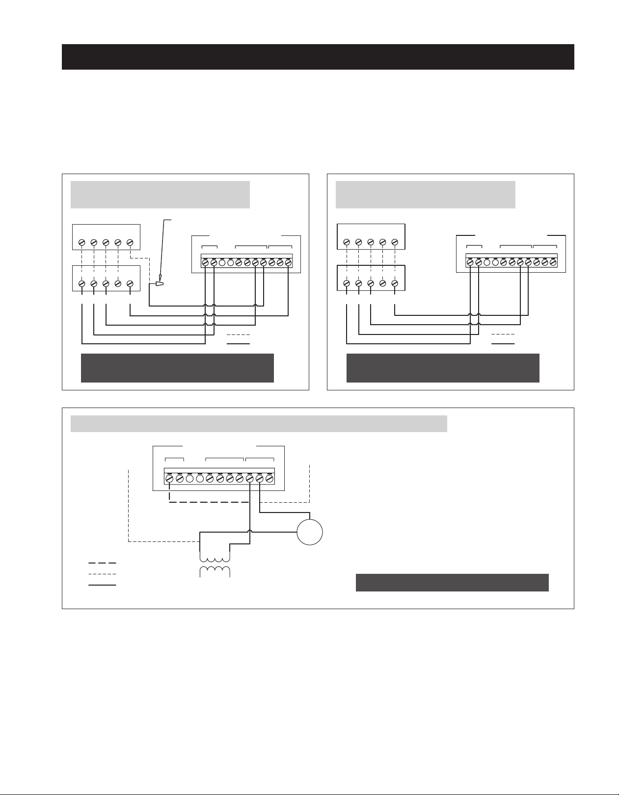
No power to the control.• Wire the control to the HVAC system as shown in the wiring diagrams
on page 5.
• Turn on power to the HVAC system.
Ventilator does not turn on,
but display on control is on.
No power to the outlet into
which the ventilator is plugged.
• Turn on switch that controls outlet.
E1 shows on display.RH sensor error.• Turn the control knob to Test/Reset position.If the error recurs,
replace the control.
E2 shows on display.Control knob error.• Turn the control knob to Test/Reset position.If the error recurs,
replace the control.
E3 shows on display.Outdoor temperature sensor
failure.
• Make sure both black wires of the sensor are connected to the ODT
terminals.
• If connected, disconnect and measure the resistance across the black
wires.If it is open or shorted, replace sensor.
Air is blowing out of the
intake hood.
Backdraft damper is open.• Make sure the unit is mounted in the proper orientation – outlet
cannot point down.
• Remove the oval outlet collar and rotate it 180° so that it closes when
the ventilator turns off.
“r#” (where # is a number)
shows on the display.
Left in test mode.• Turn knob to time setting.
aprilairepartners.com
P.O. Box 1467
Madison, WI 53701-1467
800.334.6011 F: 608.257.4357
©2021 Aprilaire. Printed in USA.
10010906 B2206530E 12.21
8
Table of contents
Other Aprilaire Fan manuals

Aprilaire
Aprilaire 8142 User manual

Aprilaire
Aprilaire 8100 User manual

Aprilaire
Aprilaire 8100 User manual

Aprilaire
Aprilaire 8145NC User manual

Aprilaire
Aprilaire 8140 User manual

Aprilaire
Aprilaire 8144NC User manual

Aprilaire
Aprilaire 8100 User manual

Aprilaire
Aprilaire 8145A User manual

Aprilaire
Aprilaire ARNHPF Manual

Aprilaire
Aprilaire 8192A User manual