Aprilaire 8145NC User manual

MODEL 8145 FRESH AIR VENTILATOR MODEL 8145NC FRESH AIR VENTILATOR
SAFETY INSTRUCTIONS
WARNING
1. 120 Volts may cause serious injury from electric shock. Disconnect electrical power before starting installation or servicing. Leave power
disconnected until installation/service is completed.
2. Sharp edges may cause serious injury from cuts. Use care when cutting plenum openings and handling duct work.
CAUTION
1. Read all instructions before beginning installation.
2. Improper installation may cause property damage or injury. Installation, service, and maintenance must be performed by a qualified service
technician.
READ AND SAVE THESE INSTRUCTIONS
VENTILATION CONTROLLER
FILTER
COVER
VENTILATION TERMINALSLOW PRESSURE
PORT
HIGH PRESSURE
PORT
INLET COLLAR AND
NORMALLY CLOSED
POWER DAMPER
OUTLET
COLLAR
SURFACE MOUNT
BRACKET LOCATION
JOIST MOUNT
BRACKET LOCATION
TABLE OF CONTENTS
Safety Instructions ...............................................1
Introduction and Compliance Statement ...........................2
Specifications ...................................................2
Install Electrical Outlet............................................2
Ventilator Location and Orientation................................3
Mount the Ventilator .............................................3
Mount Intake Hood ..............................................4
Install Ductwork .................................................4
Model 8145NC – Wiring to Various Controls.........................5
Model 8145NC – Test Mode .......................................6
Model 8145NC – Sequence of Operation............................6
Model 8145 – Wiring the Control to the HVAC System ...............6
Model 8145 – Connecting the Control to the Ventilator...............7
Model 8145 – Operation ..........................................7
Model 8145 – Test Mode ..........................................8
Measure Delivered Airflow ........................................8
Model 8145 – Set Up .............................................9
Model 8145 – Rater/Inspector Verification .........................10
Model 8145 – Sequence of Operation .............................10
Filter Cleaning...................................................11
Internal Schematics ..............................................11
Limited Warranty . . . . . . . . . . . . . . . . . . . . . . . . . . . . . . . . . . . . . . . . . . . . . . . 12
Model 8145 and 8145NC
Fresh Air Ventilator
Installation and Operating Instructions
10014353 B2208589A 4.20 English 1

INTRODUCTION AND COMPLIANCE STATEMENT
The Model 8145 and 8145NC Fresh Air Ventilators are designed to bring in precisely the right amount of outdoor air into today’s efficiently designed
homes. Duct the inlet of the ventilator to an outdoor air intake and duct the discharge to the HVAC system, then simply plug the unit in, set the
amount of needed ventilation and select the desired temperature limits.
When properly installed and set, the Model 8145 and 8145NC Fresh Air Ventilators will meet the mechanical ventilation requirements of:
Energy Star Certified Homes
EPA Indoor airPLUS
2012-2018 International Residential Code (IRC)
2012-2018 International Energy Conservation Code (IECC)
California Energy Commission Title 24
ASHRAE Standard 62.2-2010
ASHRAE Standard 62.2-2013 & 2016
SPECIFICATIONS
TABLE 1 – SPECIFICATIONS
External Static Pressure ("w.c.) Airflow (CFM) Efficacy (CFM/watt) Voltage
0.0 210 5.2
120 VAC
1 phase
60 Hz
0.2 180 4.4
0.4 150 3.5
0.6 120 2.8
13.906
12.25
13.01
23.41
19.66
INLET: ROUND COLLAR
FOR 6" DIAMETER DUCT
OUTLET: OVAL COLLAR
FOR 6" DIAMETER DUCT
CONTROL NOT INCLUDED
ON MODEL 8145NC
90-2514
FIGURE 1 – DIMENSIONS (INCHES)
INSTALL ELECTRICAL OUTLET
Install a standard NEMA 5-15 receptacle suitable for the location, near where the ventilator will be installed. The ventilator comes equipped with a
6-foot power cord with a standard 3-prong plug.
2 English

MOUNT THE VENTILATOR
1. Select the needed brackets, large or small, for mounting the ventilator (see FIGURE 3).
If mounting to the wall or hanging from joists, use the four small mounting brackets.
Ifmounting on or in between the floor joists, install all four smaller brackets for 13" on center
joists, or two small and two longer brackets for 16" on center joists.
2. Snap the brackets into the proper locations as shown in FIGURE 4. Use the mounting locations
nearest the cover for mounting between floor joists or hanging from rafters. Use the mounting
locations near the bottom of the unit for surface mounting (i.e. to a flat wall, ceiling surface or
bottom of joists).
3. Screw the ventilator brackets into joists or a strong platform using the #10 x 3/4” screws
provided. The ventilator weighs approximately 15 pounds, so do not secure into drywall alone.
BETWEEN
JOISTS
HANGING
INSTALLATION SURFACE MOUNT
90-2514
FIGURE 4 – MOUNTING BRACKET POSITIONING
VENTILATOR LOCATION AND ORIENTATION
If the outlet of the ventilator is not ducted, or if small sections of
collapsible duct (i.e. flex duct) are attached to the outlet, then the
ventilator must be mounted to minimize the possibility of accessing
moving parts (see Cautions below).
CAUTION
1. Mount the blower with the lowest, exposed moving parts at
least 8 feet (2.4 m) above floor or grade level.
2. Mount the blower at least 3.3 feet (1.0 m) from any accessible
opening of the duct.
Choose a location for the ventilator that is within 6 feet of the outlet
into which the ventilator will be plugged. Allow space for filter removal
and service as shown in FIGURE 2.
The ventilator can be mounted in any orientation.
12"
FILTER
ACCESS
24"
FAN
ACCESS
90-2514
90-2514
FIGURE 2 – CLEARANCES FOR SERVICING
FIGURE 3 – BRACKETS
English 3

MOUNT INTAKE HOOD
Install a weather tight hood with a bird screen.
Cut a hole in the exterior wall that is large enough to fit 6" insulated flexible duct through with minimal compression of the insulation. Pull the duct
through the hole and attach the flex duct to the collar of the hood. Use metal foil tape or a plastic zip-tie to secure the duct to the collar. Pull the
insulation and vapor barrier over the duct and tape it to the collar.
IMPORTANT: The end of the insulation must be sealed to prevent condensation from forming inside the insulation. If a plastic zip-tie is used to
secure the insulation to the hood collar, also tape the end to seal it against condensation problems.
Press the hood against the outside wall and secure in place with screws; seal around the perimeter of the hood with caulk.
INSTALL DUCTWORK
Install 6" diameter flexible, insulated duct
from the round inlet collar of the unit to the
intake hood and from the oval outlet collar
of the unit to the HVAC system. Duct the
outlet of the ventilator to the return side of
the HVAC system (refer to FIGURE 5).
IMPORTANT: The end of the
insulation must be sealed to prevent
condensation from forming inside
the insulation. If a plastic zip-tie is
used to secure the insulation to the
hood collar, also tape the end to seal
it against condensation problems.
FILTER
FURNACE/AIR HANDLER
AIR FLOW
FRESH AIR
VENTILATOR
FRESH AIR INTAKE DUCT
FRESH AIR
OUTSIDE
WALL
TYPICAL BASEMENT INSTALLATION
FRESH AIR
VENTILATOR
GABLE END WALL, BAND JOIST, OR PORCH SOFFIT
FRESH AIR
FRESH AIR INTAKE DUCT
FRESH AIR
INTAKE HOOD
WITH SCREEN
FRESH AIR
INTAKE HOOD
WITH SCREEN
RETURN MIXING BOX FURNACE/AIR
HANDLER
FILTER
AIR FLOW
TYPICAL ATTIC INSTALLATION
VENTILATION
TERMINALS
VENTILATION
TERMINALS
90-2514
FIGURE 5 – DUCTING IN UPFLOW AND HORIZONTAL HVAC SYSTEMS
4 English

MODEL 8145NC – WIRING TO VARIOUS CONTROLS
Suggested Controls:
• Aprilaire IAQ Control Models 8910, 8910W or 8920W
• Aprilaire Thermostat Models 8620 or 8620W
• Aprilaire Model 8120X Digital Ventilation Controller
Select the diagram that corresponds to the control to be used. Wire the controls to the HVAC equipment and any other IAQ accessory in accordance
with the literature provided with the control.
CONTROL MODULE OF IAQ CONTROL
VENT
SEE
NOTE 1
MODEL 8620/8620W THERMOSTAT
VENT
C I2
I1 Y
O/B RC
RG
Y2 W2
L T2
T1
S1
S2
W
SEE NOTE 1
R
C
Y
W
O
Gs
Gh
ODT
VENT
MODEL 8120X DIGITAL VENTILATION CONTROLLER
VENT
SEE NOTE 1
FIGURE 6 – WIRING TO IAQ CONTROL FIGURE 7 – WIRING TO THERMOSTAT
FIGURE 8 – WIRING TO MODEL 8120X
NOTE 1: An outdoor temperature sensor must be installed to use outdoor
temperature limits for ventilation control.
English 5

MODEL 8145NC – TEST MODE
After all ducting and wiring is complete, plug in the ventilator, restore power to the HVAC system and make sure the switch controlling the outlet into
which the ventilator is plugged (if applicable) is turned on.
1. Use the installed control to complete a circuit between the VENT terminals on the 8145NC.
2. Verify that the ventilator blower starts and that the integral damper opens.
3. If the ventilator has been wired to turn on the HVAC blower with ventilation, verify that the blower is on.
4. Measure the airflow (CFM) that the installed ventilator is delivering. See MEASURE DELIVERED AIRFLOW section on page 8.
5. Using the instructions provided with the installed control, adjust the ventilation settings as required.
MODEL 8145NC – SEQUENCE OF OPERATION
Refer to the installation manual provided with the control that is wired to the Model 8145NC.
MODEL 8145 – WIRING THE CONTROL TO THE HVAC SYSTEM
NOTICE
Disconnect power to HVAC system during wiring to avoid
electrical shorts.
1. Remove the control from the mounting plate as shown in FIGURE 9.
Set control aside in a safe place until all wiring has been completed.
2. Run a 6-conductor (min.) cable (for furnace/AC applications) or a
7-conductor (min.) cable between the control and the HVAC system.
3. Wire to the HVAC system in accordance with FIGURE 10 if installed in
a furnace/AC application or FIGURE 11 if installed with a heat pump.
CONTROL
CONNECTOR
CONTROL
MOUNTING
PLATE
CONTROL
VENTILATION CONTROL
R
C
Y
W
G
R
C
Y
W
G
THERMOSTAT
WIRE NUT
(FIELD
SUPPLIED)
R
C
Y
W
O
GS
GH
FURNACE
R & C = 24 VAC
Y = COOLING
W = HEAT
GS = FAN INPUT
GH = FAN OUTPUT
VENT
ODT
90-2514
FIGURE 9 – REMOVE CONTROL FROM MOUNTING PLATE
FIGURE 10 – WIRING VENTILATION CONTROL TO A FURNACE
6 English

VENTILATION CONTROL
R
C
Y
W1
G
R
C
Y
W
G
HEAT PUMP THERMOSTAT
WIRE NUT
(FIELD
SUPPLIED)
O
R & C = 24 VAC
Y = COMPRESSOR
W1 = 1st STAGE AUX. HEAT
O = REV. VALVE, COOLING
GS = FAN INPUT
GH = FAN OUTPUT
R
C
Y
W
O
GS
GH
VENT
ODT
HEAT PUMP
O
FIGURE 11 – WIRING VENTILATION CONTROL TO A HEAT PUMP
MODEL 8145 – CONNECTING THE CONTROL TO THE VENTILATOR
Plug the Control Connector into the back of the
control at the location shown in FIGURE 12. Route
the connector wire through the channels in the
control and reattach the control to the mounting
plate. Restore power to the HVAC system and plug
in the ventilator when complete.
CONTROL BACK CONTROL FRONTCONTROL MOUNTING PLATE
90-2291
FIGURE 12 – PLUG THE CONTROL INTO THE VENTILATOR
MODEL 8145 – OPERATION
The display will appear faint normally; the first press of any button will turn on the display at full power.
MIN/
HR
CODE
Use for Rater/Inspector Verification.
Press and hold for 5 seconds to
enter Test Mode or Set Up Menu.
Lights green when ventilating.
Shows the ventilation time setting (minutes/hr), mode of operation
(Code or Comfort) and whether the HVAC fan has been turned on when ventilating.
Use to override the calculated ventilation
time setting (6 – 60 minutes/hr). Press
and hold to turn ventilation OFF.
To return to the calculated setting, go
completely through the Set Up Menu.
English 7

MODEL 8145 – TEST MODE
After wiring and set up have been completed, Test Mode can be used to verify that all components in the ventilation system function and that wiring
to the HVAC system fan is correct.
2
3
TABLE 2 – MODEL 8145 TEST MODE MENU
Test Sequence Description
HP
°F
HC
%
Shows outdoor temperature or ----°F if no
separate outdoor temperature sensor has been
installed. Model 8145 installations do not require a
separate sensor – outdoor temperature is measured
by the control's on-board sensor.
tESt shows on the display, the green Fresh Air LED
will light and either the damper will open or the
power ventilator will turn on depending on what
has been wired to the VENT terminals.
1
Hold for 5 seconds.
MEASURE DELIVERED AIRFLOW
1. Make sure the ventilator is plugged in and wired to an external control (Model 8145NC) or that
the integral control is wired to the HVAC system (Model 8145).
2. Use 1/4" flexible tubing to attach a pressure gauge set to " w.c. (sometimes shown as “in. w.g.”
or “in. H2O”) to the inlet and outlet pressure ports on the ventilator. The pressure gauge should
have as small a range as possible to get a meaningful measurement – a range of 1.0" w.c. should
be sufficient. Connect the high or “+” port of the gauge to the outlet pressure port on the
ventilator, and the low or “-“ port of the gauge to the inlet pressure port on the ventilator. See
FIGURE 13.
3. Model 8145NC – Turn on the ventilator using the installed control for the Model 8145NC. This
can be done by temporarily changing the ventilation setting to 60 minutes/hour or you can
simply place a jumper between the VENT terminals of the ventilator.
Model 8145 – Turn on the ventilator by using the “Up” button to increase the ventilation setting
to 60 MIN./HR.
4. Use the label on the cover of the ventilator, or TABLE 3, to convert the pressure reading to
delivered airflow. If the pressure reading false between listed values, either use the lower value
or interpolate between values: CFM = Lower Value + [(Higher Value – Lower Value) * 10 *
(Pressure Reading – Lower Value Pressure)]. The following is an example:
a. Measured Pressure Reading is 0.34" w.c.
b. Table 3 lists 200 CFM @ 0.3" w.c. and 170 @ 0.4" w.c.
c. Either use 170 CFM or interpolate:
CFM = 200 - [(200-170) *10 *(0.34-0.3)] = 200 - [(30) *10 *(0.04)] = 200 - 12 = 188 CFM
Interpolating will demonstrate higher delivered airflow, but requires a calculation to be done.
TABLE 3 – DELIVERED AIRFLOW
CORRESPONDING TO MEASURED PRESSURE
AT VENTILATOR PRESSURE PORTS
Measured Pressure
(" w.c.)
Delivered Airflow
(CFM)
0.1 255
0.2 225
0.3 200
0.4 170
0.5 145
0.6 115
0.7 90
TABLE 2 – MODEL 8145 TEST MODE MENU
Test Sequence Description
MEASURED REQ’D CONT CFM
FAN
After 15 seconds, the HVAC fan will turn on if it has
been wired and set up to do so. The display will
show FAN along with tESt.
MIN/
HR
CODE
After 45 seconds Test Mode automatically
completes and the display returns to the operating
display.
INLET
OUTLET
Hi
-+
Lo
90-2520
FIGURE 13 – MEASURE PRESSURE AT
INLET AND OUTLET PRESSURE PORTS
8 English

MODEL 8145 – SET UP
NOTICE
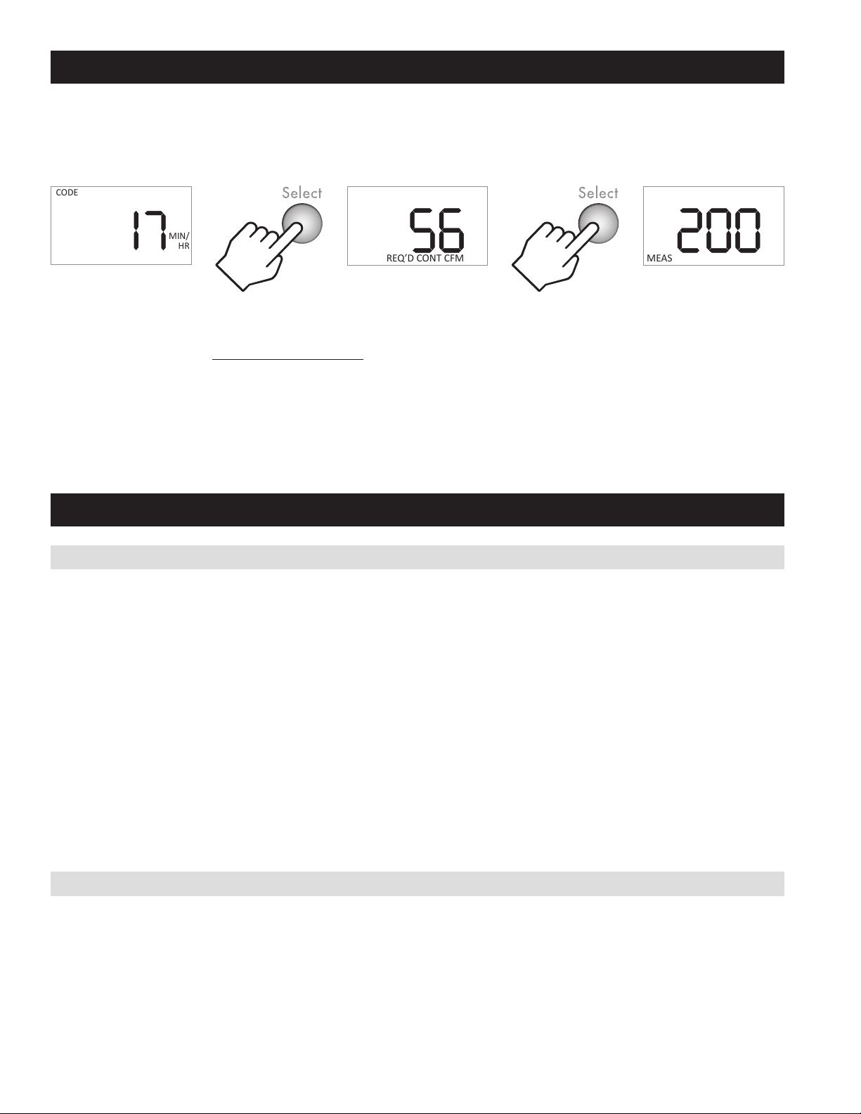
Before setting up the control for use, the amount of ventilation air being delivered (CFM) by the installed ventilation system must be measured.
1
Hold for 5 seconds, then release.
2
Throughout the Set Up Menu, the and buttons are used to change values, the Select button is used enter the value and move on to the next Set
Up Menu item.
TABLE 4 – MODEL 8145 SET UP MENU
Menu Item Values Description
HP
HC
HP or HC HP if wiring to a heat pump.
HC if wiring to furnace and AC.
CODE
#
BEDROOMS
HIGH
1 – 10
Number of bedrooms –
used to calculate required
continuous ventilation rate.
COMFORT
HOUSE
(
FT
2
)
LOW
500 – 7500 ft2
Square footage – used to
calculate required continuous
ventilation rate.
MEAS
REQ
’
D CONT
CFM
FAN
30 – 250 CFM Measured outdoor airflow
delivered during ventilation.
HP
°F
CODE NO.OF BEDROOMS
HIGH
OFF,
85°F – 105°F
Ventilation high temperature
limit. Ventilation is limited
when the outdoor temperature
exceeds the setting. Turn OFF if
no high limit is desired.
HP
°F
COMFORT HOUSE (FT
2
)
LOW
OFF,
-10°F – 40°F
Ventilation low temperature
limit. Ventilation is limited
when the outdoor temperature
falls below the setting. Turn
OFF if no low limit is desired.
MEAS REQ’D CONT CFM
FAN
On, “bLnd”, OFF
ON HVAC fan turns on
whenever ventilation occurs.
bLnd (blend) HVAC fan turns
on with ventilation only when
the outdoor temperature is
outside a set range.
OFF HVAC fan is not turned on
with ventilation.
TABLE 4 – MODEL 8145 SET UP MENU
Menu Item Values Description
HP
°F
MEAS REQ’D CONT CFM
FAN
CODE # BEDROOMS
HIGH
OFF, 60°F to 5°F
less than Vent.
High Temp. Limit
Only available when bLnd is
selected. When the outdoor
temperature is above the
setting, the HVAC fan will
be turned on to mix (blend)
outdoor air with indoor air for
tempering.
HP
°F
MEAS REQ’D CONT CFM
FAN
COMFORT HOUSE (FT
2
)
LOW
OFF, 5°F less
than Vent. Low
Temp. Limit to
55°F
Only available when bLnd is
selected. When the outdoor
temperature is below the
setting, the HVAC fan will
be turned on to mix (blend)
outdoor air with indoor air for
tempering.
CODE
COMFORT
See IMPORTANT
NOTE below.
“codE”, “cFrt”
codE No RH limits and any
missed ventilation due to
temperature is made up per
ASHRAE 62.2-2010.
cFrt (comfort) Adds indoor RH
limits to ventilation; ventilation
missed due to limits is not
made up.
HC
%
CODE # BEDROOMS
HIGH
OFF,
45% – 70% RH
Only available when cFrt is
selected. When the outdoor RH
exceeds the setting, ventilation
will not occur.
HC
%
COMFORT HOUSE (FT
2
)
LOW
OFF,
10% – 30% RH
Only available when cFrt is
selected. When the outdoor
RH drops below the setting,
ventilation will not occur.
When all Set Up Menu options have been entered, the control will
display donE.
IMPORTANT NOTE: The 8145 control senses the temperature and humidity of the outdoor air. To prevent extended periods of inactivity, set the
control mode to codE, or if setting to cFrt (comfort), set the RH limits to OFF.
English 9

MODEL 8145 – RATER/INSPECTOR VERIFICATION
To verify the ventilation time setting, press the Select button to scroll through the calculated Required Continuous CFM and the Measured CFM for
this installation. If any value does not match the expected value, the Set Up Menu must be entered to change the floor area, number of bedrooms or
measured CFM.
The calculation used for the ventilation time setting is (all calculations compliant with ASHRAE Standard 62.2-2010):
)
Required Continuous CFM
Measured CFM
(
Minutes per Hour = 60 *
Required Continuous CFM = ((Floor Area ft2*.01) + (No. of Bedrooms + 1) *7.5)
Measured CFM is entered during set up and Required Continuous CFM is calculated according to the equation below:
MIN/
HR
CODE
MEAS
REQ
’
D CONT CFM
FAN
MEAS
REQ
’
D CONT
CFM
FAN
MODEL 8145 – SEQUENCE OF OPERATION
“CODE” SETTING
The control will turn on ventilation with a heating, cooling or fan call for the set number of minutes during a one-hour cycle period. If the outdoor
temperature is above the high temperature ventilation limit, ventilation will not occur with a cool or fan call, but if it is below the low temperature
ventilation limit it will occur with a heat call. If the HVAC equipment does not turn on enough to meet the ventilation time within the hour, the control
will turn on ventilation without a call, if the outdoor air temperature is within the high and low ventilation temperature limits. The control will also
turn on the HVAC system blower, if wired and set up to do so.
If the outdoor temperature exceeds the limits set at the end of the first hour, then no additional ventilation will occur for another 60 minutes, and the
cycle period will automatically adjust to four hours. When the ventilator starts again, it will sample the air temperature and if in range, will meet the
set amount of ventilation during the four-hour cycle period. For example, if the Vent Time was set to 25 minutes per hour and the air temperature fell
below the low limit setting ventilation would only occur during a heating call. If the heating only operated for 10 minutes during the hour, the control
will automatically change the cycle period to four hours and work to provide the additional 90 total minutes of ventilation (25 min/hr * 4 hours = 100
minutes, minus the 10 minutes of ventilation that occurred during heating) during the four-hour cycle period.
If the air temperature is still out of range, the control will automatically switch to an 8-hour cycle period, then a 12-hour cycle period and finally a
24-hour cycle period. During 8, 12 and 24 hour cycle periods, the total ventilation time increases to compensate for ventilation effectiveness as defined
in ASHRAE Standard 62.2-2010. When the cycle period automatically adjusts to 24-hours, the control will turn on ventilation to meet the requirements
even if the temperature is outside of the set limits.
“COMFORT” SETTING
The control will turn on ventilation with a heating, cooling or fan call by the HVAC equipment, if the outdoor air temperature is within the high and
low ventilation temperature limits and the outdoor RH is within the high and low RH limits, for the set number of minutes during a one-hour cycle
period. If the HVAC equipment does not turn on enough to meet the ventilation time within the hour, the control will turn on ventilation without a
call, if the outdoor air temperature and indoor RH is within the set limits. The control will also turn on the HVAC system blower, if wired and set up to
do so.
10 English

FILTER CLEANING
Normally, the fresh air filter will need to be removed and cleaned every six months, but check it after the first three months following installation to
determine if more or less frequent cleaning will be necessary. After cleaning the filter inside the ventilator, clean off the screen at the fresh air intake
hood on the outside of the house. The most common cause of reduced ventilation is a clogged air intake hood.
To clean the ventilator filter
(see FIGURE 14):
1. Flex the outside edges of
the filter door to disengage
it from the housing.
2. Lift the filter door and
remove the filter from the
ventilator.
3. Use water to rinse the
filter and shake the excess
moisture off the filter.
4. Replace the filter in the
ventilator and press the
outside edges of the filter
door to snap it in place.
FILTER DOOR
FIGURE 14
90-2514
INTERNAL SCHEMATICS
RED
GRN
BLU
BRN
GRN
L2-WHT
L1-BLK
BLK
WHT
YLW
YLW
ORG
N
L
120 VAC
CON3
CON2
CON3
ORG
R
C
Y
W
O
Gs
Gh
VENT
ODT
WHT
RED
BLU
CAPPED RED & WHITE WIRES ARE LOCATED INSIDE THE FILTER DOOR TO POWER
THE CONTROL (R & C TERMINALS) FROM THE POWER PCB ASSEMBLY. USE ONLY
IF THE VENTILATON CONTROLLER WILL NOT BE WIRED TO THE HVAC SYSTEM.
M
M
BLOWER
RUN CAPACITOR
CHASSIS GROUND
GND
CHASSIS
GROUND
DAMPER
MOTOR
POWER PCB ASSEMBLY
VENTILATION CONTROLLER
FIGURE 15 – MODEL 8145 INTERNAL SCHEMATIC
English 11

LIMITED WARRANTY
Your Research Products Corporation Aprilaire® Fresh Air Ventilator is expressly warranted for five (5) years from date of installation to be free from defects in materials or workmanship.
Research Products Corporation’s exclusive obligation under this warranty shall be to supply, without charge, a replacement for any component which is found to be defective within such
five (5) year period and which is returned not later than thirty (30) days after said five (5) year period by you to either your original supplier or to Research Products Corporation, Madison,
Wisconsin 53701, together with the model number and installation date of the ventilator.
THIS WARRANTY SHALL NOT OBLIGATE RESEARCH PRODUCTS CORPORATION FOR ANY LABOR COSTS AND SHALL NOT APPLY TO DEFECTS IN WORKMANSHIP OR MATERIALS
FURNISHED BY YOUR INSTALLER AS CONTRASTED TO DEFECTS IN THE VENTILATOR ITSELF.
IMPLIED WARRANTIES OF MERCHANTABILITY OR FITNESS FOR A PARTICULAR PURPOSE SHALL BE LIMITED IN DURATION TO THE AFORESAID FIVE YEAR PERIOD. RESEARCH PRODUCTS
CORPORATION’S LIABILITY FOR INCIDENTAL OR CONSEQUENTIAL DAMAGES, OTHER THAN DAMAGES FOR PERSONAL INJURIES, RESULTING FROM ANY BREACH OF THE AFORESAID
IMPLIED WARRANTIES OR THE ABOVE LIMITED WARRANTY IS EXPRESSLY EXCLUDED. THIS LIMITED WARRANTY IS VOID IF DEFECTS(S) RESULT FROM FAILURE TO HAVE THIS UNIT
INSTALLED BY A QUALIFIED HEATING AND AIR CONDITIONING CONTRACTOR. IF THE LIMITED WARRANTY IS VOID DUE TO FAILURE TO USE A QUALIFIED CONTRACTOR, ALL DISCLAIMERS
OF IMPLIED WARRANTIES SHALL BE EFFECTIVE UPON INSTALLATION.
Some states do not allow limitations on how long an implied warranty lasts or the exclusion or limitation of incidental or consequential damages so the above exclusion or limitations may
not apply to you.
This warranty gives you specific legal rights and you may also have other rights which vary from state to state.
WARRANTY REGISTRATION
Visit us online at www.aprilaire.com to register your Aprilaire product. If you do not have online access, please mail a postcard with your name, address, phone number, email address, product
purchased, model number, date of purchase, and dealer name and address to: Research Products Corporation, P.O. Box 1467, Madison, WI 53701.
Your warranty registration information will not be sold or shared outside of this company.
TERMINAL
BLOCK
M
RED
BLOWER
RUN CAPACITOR
GRN
BLU
BRN
GRN
L2-WHT
L1-BLK
CHASSIS GROUND
GND
CHASSIS
GROUND
BLK
WHT
M
YLW
YLW
ORG
DAMPER
MOTOR
N
L
120 VAC
CON3
CON2
BLU
CON3
ORG
POWER PCB ASSEMBLY
FIGURE 16 – MODEL 8145NC INTERNAL SCHEMATIC
AprilairePartners.com
P.O. Box 1467
Madison, WI 53701-1467
800.334.6011 F: 608.257.4357
Printed in USA
©2020 Aprilaire – Division of Research Products Corporation
12 English
This manual suits for next models
1
Table of contents
Other Aprilaire Fan manuals

Aprilaire
Aprilaire 8142 User manual

Aprilaire
Aprilaire 8144NC User manual

Aprilaire
Aprilaire 8142A User manual

Aprilaire
Aprilaire ARNHPF Manual

Aprilaire
Aprilaire 8192A User manual

Aprilaire
Aprilaire 8100 User manual

Aprilaire
Aprilaire 8190FF User manual

Aprilaire
Aprilaire 8100 User manual

Aprilaire
Aprilaire 8145A User manual

Aprilaire
Aprilaire 8140 User manual