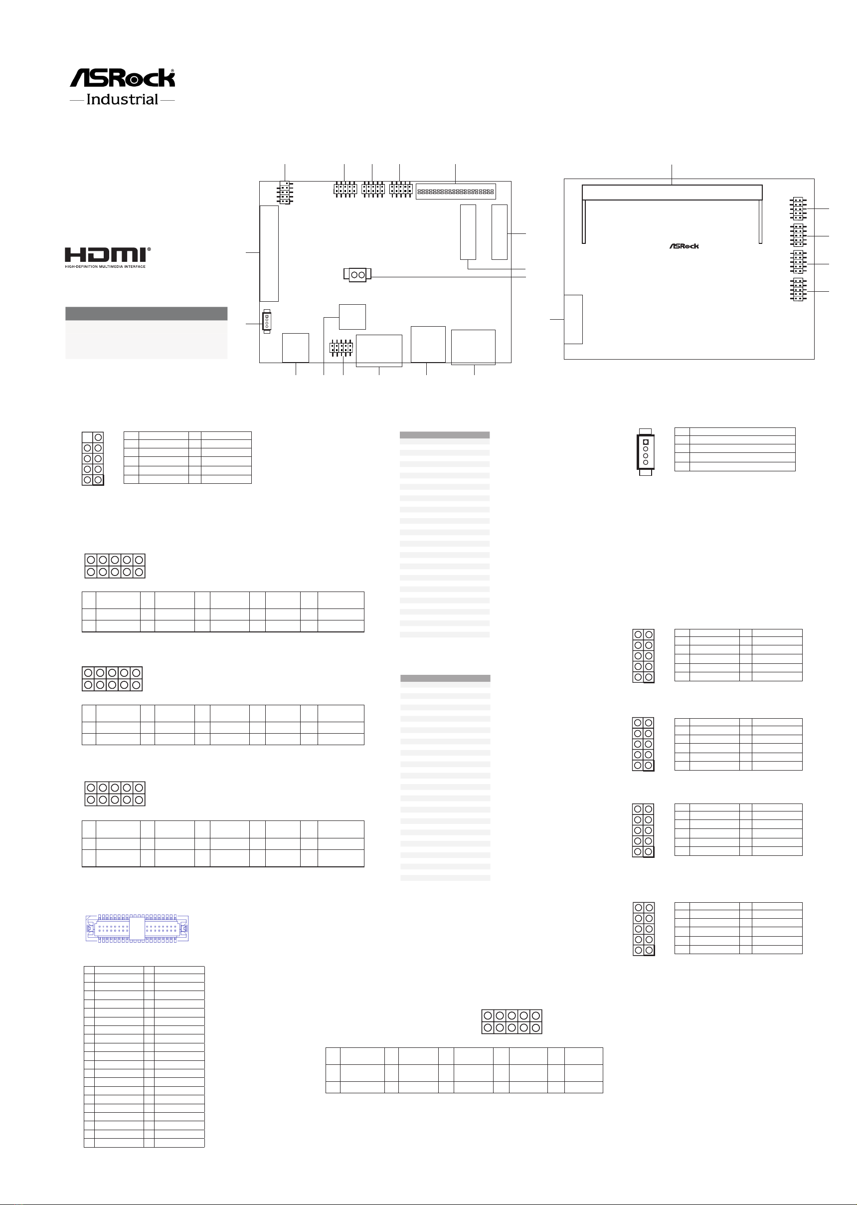
manuals.online logo
Brands
  1. Home
  2. •
  3. Brands
  4. •
  5. ASRock Industrial
  6. •
  7. Motherboard
  8. •
  9. ASRock Industrial SOM-P104 Service manual

ASRock Industrial SOM-P104 Service manual

Other manuals for SOM-P104

2

Other ASRock Industrial Motherboard manuals

ASRock Industrial IMB-X1712 User manual

ASRock Industrial

ASRock Industrial IMB-X1712 User manual

ASRock Industrial N3160-NUC IPC User manual

ASRock Industrial

ASRock Industrial N3160-NUC IPC User manual

ASRock Industrial 4X4-7840U-1U User manual

ASRock Industrial

ASRock Industrial 4X4-7840U-1U User manual

ASRock Industrial IMB-157 User manual

ASRock Industrial

ASRock Industrial IMB-157 User manual

ASRock Industrial NUC-J6412 Service manual

ASRock Industrial

ASRock Industrial NUC-J6412 Service manual

ASRock Industrial IMB-X1314 Service manual

ASRock Industrial

ASRock Industrial IMB-X1314 Service manual

ASRock Industrial NUC-1360P/D5 User manual

ASRock Industrial

ASRock Industrial NUC-1360P/D5 User manual

ASRock Industrial IMB-1232-WV User manual

ASRock Industrial

ASRock Industrial IMB-1232-WV User manual

ASRock Industrial IMB-1714 Service manual

ASRock Industrial

ASRock Industrial IMB-1714 Service manual

ASRock Industrial IMB-1231 User manual

ASRock Industrial

ASRock Industrial IMB-1231 User manual

ASRock Industrial IMB-R1000 User manual

ASRock Industrial

ASRock Industrial IMB-R1000 User manual

ASRock Industrial SOM-P104 User manual

ASRock Industrial

ASRock Industrial SOM-P104 User manual

ASRock Industrial IMB-1006 User manual

ASRock Industrial

ASRock Industrial IMB-1006 User manual

ASRock Industrial IMB-1230 Service manual

ASRock Industrial

ASRock Industrial IMB-1230 Service manual

ASRock Industrial NUC-155H User manual

ASRock Industrial

ASRock Industrial NUC-155H User manual

ASRock Industrial IMB-1235 Service manual

ASRock Industrial

ASRock Industrial IMB-1235 Service manual

ASRock Industrial IMB-1235 User manual

ASRock Industrial

ASRock Industrial IMB-1235 User manual

ASRock Industrial STX-1000B Service manual

ASRock Industrial

ASRock Industrial STX-1000B Service manual

ASRock Industrial NUC-J6412 User manual

ASRock Industrial

ASRock Industrial NUC-J6412 User manual

ASRock Industrial IMB-1713 Service manual

ASRock Industrial

ASRock Industrial IMB-1713 Service manual

ASRock Industrial IMB-159 User manual

ASRock Industrial

ASRock Industrial IMB-159 User manual

ASRock Industrial IMB-V2000 User manual

ASRock Industrial

ASRock Industrial IMB-V2000 User manual

ASRock Industrial COM-652 User manual

ASRock Industrial

ASRock Industrial COM-652 User manual

ASRock Industrial IMB-1315 User manual

ASRock Industrial

ASRock Industrial IMB-1315 User manual

Popular Motherboard manuals by other brands

Gigabyte MNJ190I-FH user manual

Gigabyte

Gigabyte MNJ190I-FH user manual

Biostar HI-FI-Z87X-3D Setup manual

Biostar

Biostar HI-FI-Z87X-3D Setup manual

Atmel SAM9753PIA-DK user guide

Atmel

Atmel SAM9753PIA-DK user guide

Coapt GEN2 Handbook

Coapt

Coapt GEN2 Handbook

Supero SUPER P4DL6 user manual

Supero

Supero SUPER P4DL6 user manual

Cypress CY3210-PSoCEVAL1 quick start guide

Cypress

Cypress CY3210-PSoCEVAL1 quick start guide

ASROCK B660M-HDV manual

ASROCK

ASROCK B660M-HDV manual

Fujitsu D2831 Short description

Fujitsu

Fujitsu D2831 Short description

Industrial Computers ADE-6050 user manual

Industrial Computers

Industrial Computers ADE-6050 user manual

Asus TUF Z270 MARK 2 manual

Asus

Asus TUF Z270 MARK 2 manual

DFI NB71-BC user manual

DFI

DFI NB71-BC user manual

ASROCK H61 Pro BTC user manual

ASROCK

ASROCK H61 Pro BTC user manual

Norco POS-7893 user manual

Norco

Norco POS-7893 user manual

Intel DG965MS specification

Intel

Intel DG965MS specification

Asus B85M-VIEW PAKER user manual

Asus

Asus B85M-VIEW PAKER user manual

Asus P5G41T-M LX V2 user manual

Asus

Asus P5G41T-M LX V2 user manual

Gigabyte GA-K8VT800-RH user manual

Gigabyte

Gigabyte GA-K8VT800-RH user manual

Gigabyte Z790M AORUS ELITE user manual

Gigabyte

Gigabyte Z790M AORUS ELITE user manual

manuals.online logo
manuals.online logoBrands
  • About & Mission
  • Contact us
  • Privacy Policy
  • Terms and Conditions

Copyright 2025 Manuals.Online. All Rights Reserved.

15 : 4-Pin CPU
FAN Connector
16 : MIOE1
Support interface:
3* PCIe Gen3x1
1* USB3.2 Gen2
1* USB2.0
1* DP1.4
17 : DDR5 (DDR5_A1)
18 : C
OM Port Header (COM3)
19 : C
OM Port Header (COM1)
20 :
HD Audio Header
21 :
System Panel Header
22 : MIPI Connector (MIPI1)
6 : M.2 Key-M Socket (M2_M1)
7 : M.2 Key-E Socket (M2_E1)
8 : Battery Connector (BAT1)
9 : 2.5G LAN Port (LAN1)
10 : USB3.2 Gen2 Port (USB3_1)
11 : HDMI Port (HDMI1)
12 : JP_SET1
1-2: AT mode(short), ATX mode(open)
3-5: Auto Clear CMOS
5-6: Clear CMOS
13 : BIOS ROM (U2)
14 : DC-In Jack (DC_JACK1)
1
: USB2.0 Header (USB2_2_3) (2.0mm Pitch)
2 : Digital Input / Output Pin Header
(JGPIO1)
3 : LVDS_PJ1
4 : BLT_SEL1
5 :
LVDS Panel Connector
Jumpers and Headers Setting Guide
SOM-P104
The terms HDMI™ and HDMI High-Denition
Multimedia Interface, and the HDMI logo are
trademarks or registered trademarks of HDMI
Licensing LLC in the United States and other
countries.
1
2
9
10
2 10
1 9
Revision History
Date Description
December 12, 2022 First Release
February 23, 2023 Second Release
March 21, 2023 Third Release
24
135
7
6
8
10 9
11
13 12
15
14
LVDS1
1
1
JGPIO1
M2_E1
1
JP_SET1
BLT_SEL1
LVDS_PJ1
DC_JACK1
U2
HDMI1
USB3.2 Gen2:
USB3_1
1
USB2_2_3
1 1
M2_M1
LAN1
MIOE1
16
CPU_FAN1
1
BAT1
BAT1
17
18
19
DDR5_A1 (Support DDR5L Only)
1
COM1
1
COM3
1
HD_AUDIO1
1
PANEL1
Industrial
20
21
22
MIPI1
Top Side: Rear Side:
139
40
2
40 2
39 1
Pin Signal Name Pin Signal Name
2 LCD_VCC 1 LCD_VCC
4 N/A 3 +3.3V
6 LVDS_A_DATA0# 5 N/A
8 GND 7 LVDS_A_DATA0
10 LVDS_A_DATA1 9 LVDS_A_DATA1#
12 LVDS_A_DATA2# 11 GND
14 GND 13 LVDS_A_DATA2
16 LVDS_A_DATA3 15 LVDS_A_DATA3#
18 LVDS_A_CLK# 17 GND
20 GND 19 LVDS_A_CLK
22 LVDS_B_DATA0 21 LVDS_B_DATA0#
24 LVDS_B_DATA1# 23 GND
26 GND 25 LVDS_B_DATA1
28 LVDS_B_DATA2 27 LVDS_B_DATA2#
30 LVDS_B_DATA3# 29 DPLVDD_EN
32 GND 31 LVDS_B_DATA3
34 LVDS_B_CLK 33 LVDS_B_CLK#
36 CON_LBKLT_EN 35 GND
38 LCD_BLT_VCC 37 CON_LBKLT_CTL
40 LCD_BLT_VCC 39 LCD_BLT_VCC
Pin Signal Name Pin Signal
Name Pin Signal
Name Pin Signal
Name Pin Signal Name
2GPP_B15 4GPP_E1 6GPP_E2 8GPP_E13 10 GND
1SIO_GP63 3SIO_GP64 5SIO_GP86 7SIO_GP87 9+JGPIOPWR
1
2
9
10
9 1
10 2
1
2
9
10
9 1
10 2
1
2
9
10
9 1
10 2
Pin Signal Name Pin Signal
Name Pin Signal
Name Pin Signal
Name Pin Signal
Name
9JGPIO_VSET 7JGPIO_
VSET 5RTC RST# 3RTCRST2# 1AT/ATX
mode
10 +3V 8GND 6GND 4GND 2GND
Pin Signal Signal Pin
1GND +3. 3V 2
3GND +3. 3V 4
5NA NA 6
7NA NA 8
9GND HD_LED 10
11 NA +3.3V 12
13 NA +3.3V 14
15 GND +3. 3V 16
17 NA +3.3V 18
19 NA NA 20
21 GND NA 22
23 NA NA 24
25 NA NA 26
27 GND NA 28
29 NA NA 30
31 NA NA 32
33 GND USB D+ 34
35 NA USB D- 36
37 NA NA 38
39 GND SMB_CLK 40
41 PER n0/SATA-B+ SMB_ DATA 42
43 PERp0/SATA-B- NA 44
45 GND NA 46
47 PETn0/SATA-A- NA 48
49 PETP0/SATA-A+ PERST# 50
51 GND CLKREQ# 52
53 PEFCLKn WA K E # 54
55 PEFCLKp NA 56
57 GND NA 58
67 NA NA 68
69 PEDET +3.3V 70
71 GND +3. 3V 72
73 GND +3. 3V 74
75 GND
Pin Signal Signal Pin
1GND +3VSB 2
3USB_D+ +3VSB 4
5USB_D- NA 6
7GND NA 8
9C NV_ WG R _D 1- CNV_RF_RESET 10
11 C NV_ WG R _D 1+ NA 12
13 GND MODEM_CLKREQ 14
15 C NV_ WG R _D 0 - NA 16
17 C NV_ WG R _D 0 + GND 18
19 GND BC_PROCHOT 20
21 C NV_ WG R _C L K- C N V_ BR I _ RS P 22
23 C NV_ WG R _C L K+
33 GND CNV_BGI_DT 32
35 PE Tp CNV_RGI_RSP 34
37 PETn CN V_ BR I_DT 36
39 GND NA 38
41 PERp NA 40
43 PERn NA 42
45 GND CNV_PA_BLANKING 44
47 PEFCLKp CNV_MFUA RT2_T X D 46
49 PEFCLKn C N V_ MF UA R T2 _ R X D 48
51 GND SUSCLK 50
53 CLKREQ# PERST# 52
55 NA W_DISABLE1# 54
57 GND W_DISABLE2 # 56
59 CNV_W T_D1- SMB _DATA 58
61 CNV_W T_D1+ SMB_CLK 60
63 GND NA 62
65 CNV_W T_D0- NA 64
67 CNV_W T_D0+ NA 66
69 GND NA 68
71 CNV_W T_C LK- NA 70
73 CNV_W T_C LK+ +3VSB 72
75 GND +3VSB 74
Pin Signal Name Pin Signal
Name Pin Signal
Name Pin Signal
Name Pin Signal Name
9 +12V 7 +12V 5 +5V 3 +5V 1 +3V
10 BLTVCC 8 BLTVCC 6 BLTVCC 4 PLVDD 2 PLVDD
Pin Signal Name Pin Signal
Name Pin Signal
Name Pin Signal
Name Pin Signal Name
9 GND 7 BLT_CTL 5 BLT_EN 3 BLT_VCC 1 BLT_VCC
10 GND 8 GPIO_
TEST# 6 PWRDN 4 BLUP 2 BLDN
Pin Signal Name Pin Signal Name
10 N/A 9 N/A
9 CCTS#3 7 RRTS#3
6 DDSR#3 5 GND
4 DDTR#3 3 TTXD3
2 RRXD3 1 DDCD#3
1
1
Pin Signal Name Pin Signal Name
10 N/A 9 N/A
9 CCTS#1 7 RRTS#1
6 DDSR#1 5 GND
4 DDTR#1 3 TTXD1
2 RRXD1 1 DDCD#1
1
Pin Signal Name Pin Signal Name
10 MIC1_L 9 MIC1_R
9 AGND_A 7 MIC1_JD
6 LIN1_L 5 FRONT_L
4 LIN1_JD 3 FRONT_JD
2 LIN1_R 1 FRONT_R
1
Pin Signal Name Pin Signal Name
10 N/A 9 GND
9 GND 7 RESET#
6 PWRBTN# 5 GND
4 PLED- 3 HDLED-
2 PLED+ 1 HDLED+
1
Pin Signal Name Pin Signal Name
10 9 DUMMY
9 GND 7 GND
6 P+ 5 P+
4 P- 3 P-
2 USB_PWR 1 USB_PWR
1
Pin Signal Name
1 GND
2 +5V
3 FAN_SPEED
4 FAN_SPEED_CONTROL
Installation of ROM Socket
* Do not apply force to the actuator cover after ic inserted.
* Do not apply force to actuator cover when it is opening over 120
degree, Otherwise, the actuator cover may be broken.
* The yellow dot (Pin1) on the ROM must be installed at pin1 position of
the socket (white arrow area).
* Make sure the white dot on the ROM is installed outwards of the
socket.
* For further details of how to install ROM, please refer to ASRI website.
Warning: If the installation does not follow as the picture, then it
may cause severe damage to chipset & MB.