APS HEPA-FLOW APS625 User manual

HEPA-FLOW™
Room Air Purifier
Class II Medical Device
USE AND CARE MANUAL
Model: APS625

Page 2
Contents
WELCOME! .......................................................................................................... 3
INTRODUCTION................................................................................................... 4
ESSENTIAL SAFETY PRECAUTIONS.......................................................................... 4
WHAT THE APS625 DOES..................................................................................... 6
WHERE UNIT CAN BE INSTALLED............................................................................ 7
HOW THE UNIT FILTERS AND PURIFIES THE AIR ....................................................... 7
SET-UP AND OPERATION.................................................................................. 8
UNPACKING .......................................................................................................... 8
PACKING LIST ....................................................................................................... 8
ROOM REQUIREMENTS .......................................................................................... 8
SET-UP PROCEDURES........................................................................................... 8
TURNING THE UNIT ON.......................................................................................... 9
TURNING THE UNIT OFF......................................................................................... 9
ADJUSTING THE LOW FAN SPEED ......................................................................... 10
MAINTENANCE.................................................................................................. 11
THE IMPORTANCE OF GOOD MAINTENANCE ........................................................... 11
MONTHLY MAINTENANCE ..................................................................................... 11
ANNUAL MAINTENANCE........................................................................................ 14
APS 625 MAINTENANCE LOG .............................................................................. 18
Appendix............................................................................................................ 19
EQUIPMENT OPTIONS .......................................................................................... 19
TECHNICAL SUPPORT:(952) 226-1112 ................................................................ 19
APS NEGATIVE PRESSURIZATION KIT ................................................................... 20
PARTS, SPECIFICATIONS AND APPROVALS................................................ 22
EQUIPMENT WARRANTY................................................................................. 25

Page 3
Welcome!
Congratulations, you have acquired a high quality Air
Purification system.
The APS625 HEPA-FLOW™ Air Purification System is
accepted and used by the recipient individual or group
with the understanding that Air-Pure Systems, makes
no warranties, express or implied, concerning the
product's suitability for any particular application, and Air-
Pure Systems shall be under no liability whatsoever to
any such individual or group entity by reason of any use
made thereof. Due to Air-Pure Systems continuing
program of product improvements, specifications are
subject to change without notice.
This Use and Care Guide has been developed by Air-
Pure Systems to support the installation and operation of
the APS625 Air Purification System. Information in this
document is subject to change. While every effort has
been made to present correct information, the company
disclaims liability for difficulties resulting from inadvertent
errors or from misinterpretation of the materials contained
herein.
Serial No. ____________________
For warranty information, see the Appendix section of this Use and Care Guide.
Warrantor and Technical Assistance:
Air-Pure Systems
16873 Fish Point Rd SE
Prior Lake, MN 55372
(952)226-1112
Visit us on the internet: http://www.airpuretech.com
Email us at: info@airpuretech.com
Copyright © 2006 Air-Pure Systems HEPA-FLOW™ is a trademark of Air-Pure Systems

Page 4
INTRODUCTION
!!READ AND SAVE THESE INSTRUCTIONS!!
Essential Safety Precautions
Warning
TO REDUCE OR AVOID THE HAZARDS OF ELECTRICAL SHOCK AND
FIRE:
• Do not expose this appliance to rain or moisture.
• Do not handle the power cord with wet hands.
• Do not pull the power cord when disconnecting it from an AC outlet.
Grasp the plug, not the cord.
• Do not place anything directly on top of the unit.
• If water is spilled on the unit, unplug the power cord immediately
and take the unit to an authorized service center for a safety inspection.
In addition to the specific warnings noted above, observe the following points related to
the unit:
1. Read the Use and Care Guide before operating this equipment.
2. Retain the Use and Care Guide, since the safety and operating instructions could be
required for future reference.
3. Heed warnings associated with handling, installing, using, and maintaining this equipment.
4. Follow all set-ups, operating, and use instructions.
5. When cleaning and servicing, unplug this product from the wall outlet before cleaning or
servicing the unit.
6. Water and Moisture: Do not use this product near water — for example, near a bathtub,
washbowl, kitchen or bathroom sink, or laundry tub, in a wet basement, or near a swimming
pool.
7. Power Sources: This equipment should be operated only from the type of power source
indicated on the marking label. If you are not sure of the type of power supply available to
you in your facility, consult your dealer or Power Company.

Page 5
8. Grounding or Polarization: This unit is equipped with a polarized alternating-current (AC)
plug (a plug having one blade wider than the other). For safety purposes, this plug will fit
into the power outlet only one way. If you are unable to insert the plug fully into the outlet,
try reversing the plug. If it still does not fit, call an electrician to replace this obsolete outlet.
Do not attempt to bypass this safety feature.
9. Power-Cord Protection: Power-supply cords should be routed so that they will not be
walked on or pinched by objects placed on or against them. Pay particular attention to
cords at plugs, convenience receptacles, and the point where they exit the unit.
10.Do not overload wall outlets and extension cords — this practice can result in risk of fire or
electrical shock.
11.Replacement Parts: When parts need servicing, service technicians should use
replacement parts specified by the manufacturer or parts having the same characteristics
as the original part. Unauthorized substitutions may result in fire, electrical shock, or other
hazards.
12.After any service or repair to this equipment, ask the service technician to perform safety
checks to assure that the unit is operating properly.
Important
Although the HEPA-FLOW™ APS625 is an effective means of
reducing airborne contaminants; it is intended to be used in
conjunction with standard universal precautions, such as the use of
facial respirators, gloves, gowns, and other protective measures.

Page 6
What the APS625 Does
The HEPA-FLOW™APS625 is an effective defense against viable and nonviable airborne
contaminants such as lint, dust, spores, pollen, bacteria, molds, and other microorganisms. It
combines three methods of air-quality control:
• High-efficiency particulate air (HEPA) filtration.
• Ultraviolet germicidal irradiation (UVGI).
• Room pressurization capability.
Ideal for use in a variety of settings — including Hospital Isolation, Emergency, Bronchoscopy,
and Autopsy Rooms; Nursing Homes, Rehab Centers, Correctional Facilities and Laboratories
— this compact stand-alone unit provides efficient, flexible air filtration and purification.
The HEPA-FLOW™ Mobile APS625

Page 7
Where Unit Can Be Installed
The HEPA-FLOW™APS625 is a mobile floor unit. Please see "Equipment Options" in the
Appendix for accessories required in specific applications.
How the Unit Filters and Purifies the Air
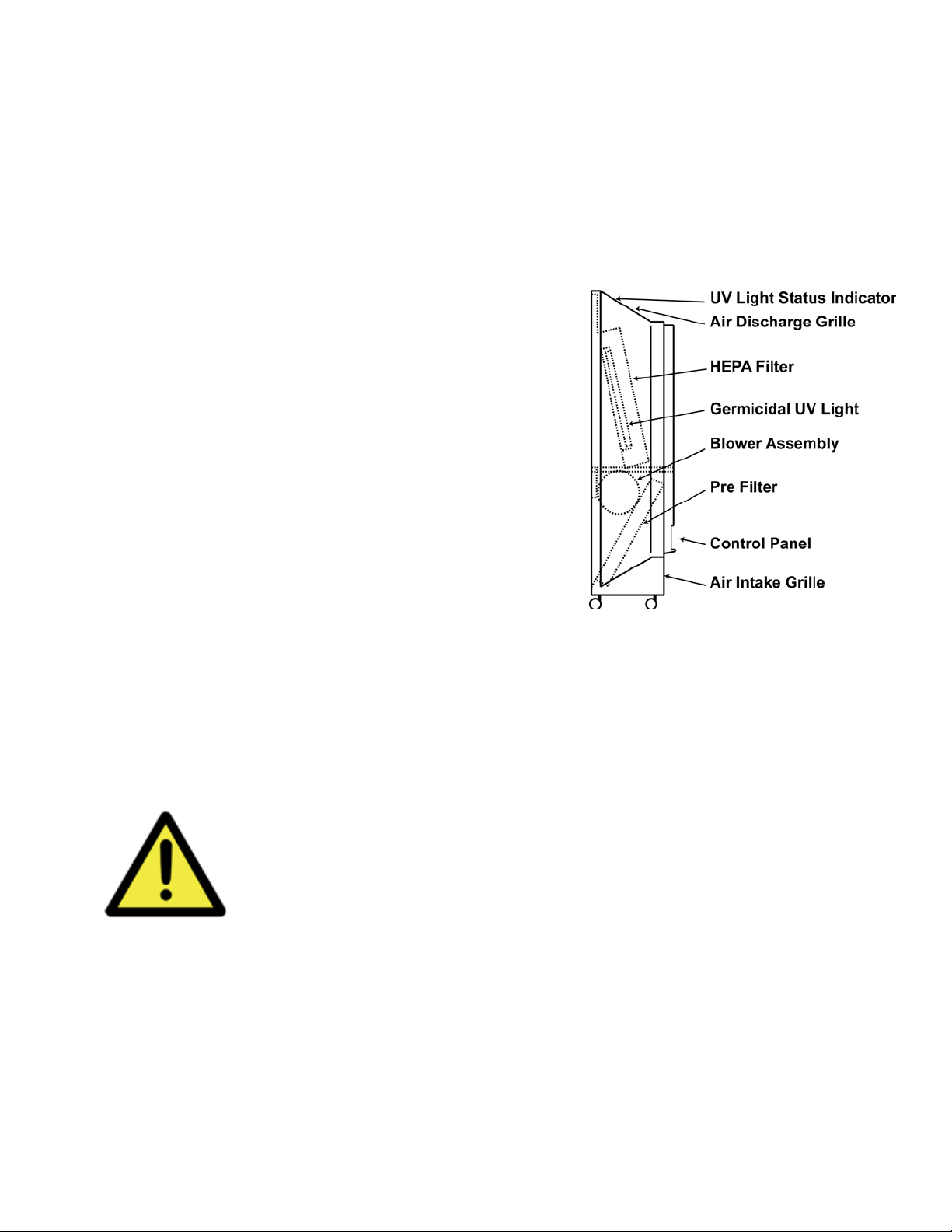
The HEPA-FLOW™ APS625 draws room air in through a return air grille at the bottom and
discharges filtered air (supply air) through a grille at the top. This airflow direction cleans the
room air of dust, dirt, and other particles by pulling them down, out of the air and provides
cleaned air at the breathing zone.
As air enters the bottom of the unit, it passes through a
protective grille that prevents objects(pieces of paper,
etc.) from entering the unit and helps assure safety. The
air then passes through a 30% efficient, ASHRAE
antimicrobial filter. This disposable filter, called the pre-
filter, prolongs the life of the finer HEPA filter by
removing large particles from the incoming air.
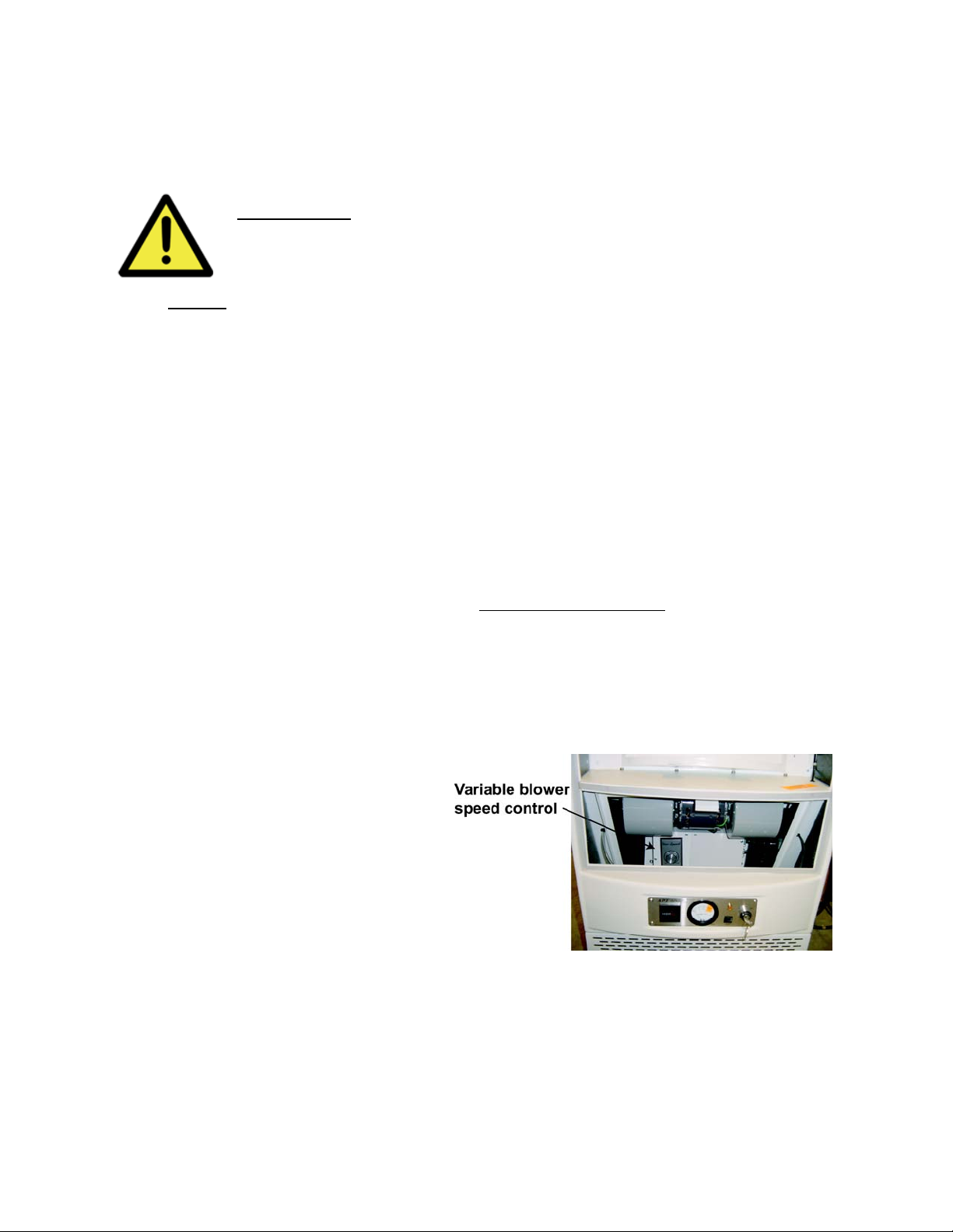
A blower then forces the air into the unit's upper
chamber, where it is exposed to germicidal ultraviolet
light (253.7nm). Trapped on the inlet side of the HEPA
filter, viable microorganisms are continuously exposed
to this UV radiation, which changes the DNA structure
of the particles and renders them harmless.
Finally, the air passes through the HEPA filter, which is 99.97% efficient in capturing particles
0.3 microns or larger. Particles this size—10,000 times smaller than a human hair and 2,500
times too small to be seen by the unaided human eye—include pollens, lung damaging dust,
bacteria, viruses, and tobacco smoke.
The HEPA filter is firmly sealed to prevent air from leaking around it, assuring that all
processed air has been both radiated and filtered. The sterilized air exits into the room through
the discharge grille at the top of the unit providing cleaned air at the breathing zone.
Important
Although the HEPA-FLOW™ APS625 is an effective means of reducing
airborne contaminants; it is to be used in conjunction with standard
universal precautions, such as the use of facial respirators, gloves,
gowns, and other protective measures.

Page 8
Set-Up and Operation
Unpacking
To unpack the HEPA-FLOW™APS625, complete the following steps:
1. Check the shipping box for damage. Call Air-Pure Systems - and the shipping company —
right away if any damage is evident.
2. Remove unit off of pallet, stand the shipping box upright, open it, remove packing materials
and wheel unit out.
3. Check the unit for physical damage. Call Air-Pure Systems immediately if any damage is
present.
4. Verify the contents of the shipment against the packing list.
5. Record serial number from back of unit onto the manuals or other place of reference.
Packing List
1. APS625 with HEPA Filter, UV Lamp, and Prefilter installed in unit (the UV Lamp and
Prefilter are not visible without opening the unit).
2. 2 Manuals
3. 2 Service Keys
4. 2 Operator’s Keys
5. UL Listed Hospital Grade Cable
6. Certificate of Performance
Call (952) 226-1112 to report any damage during shipment or missing parts.
Room Requirements
The HEPA-FLOW™ APS625 requires a standard 110-volt, 60-Hz, three hole grounded
electrical outlet on a 15-amp (minimum) circuit. (A 220-volt, 50Hz model is also available.)
The unit comes with an UL Listed Hospital Grade Cable (part no. 14-6066).
WARNING: Do not use an adapter with an ungrounded two-hole outlet to
connect this unit. If necessary, call an electrician to update your electrical
plugs and/or circuitry to accommodate the unit.
If the room needs to be pressurized, an opening to air outside the room is also
required. See "Equipment Options" in the Appendix for accessory products
designed for use in pressurizing the room.
Set-Up Procedures
1. The APS625 is a freestanding floor unit that can be rolled easily to the desired
position in the room. The negative pressurization kit can be installed on any of the
different options. See Equipment Options section of Appendix for different types of
units.

Page 9
2. Roll the unit to the desired location. Position the unit close enough to a 110-volt (or,
if appropriate, 220-volt) grounded electrical outlet so that you can plug the unit in
without using an extension cord. Make sure the plug is accessible—the unit will need
to be unplugged monthly for routine maintenance.
Note: To achieve proper airflow, be sure the return-air grille (at the bottom) and the
clean-air discharge grille (at the top) are both unobstructed. There should be a free flow
of air into and out of the unit.
3. Plug one end of the power cord into the plug on the side of the unit. Press the cord
fully into position so that it's firmly seated.
4. Plug the other end of the power cord into the grounded electrical outlet in the room.
Make sure the cord is neatly and safely arranged so that people don't trip on it or
walk over it.
Turning the Unit On
1. Be sure the power cord is plugged into the unit and that the unit is plugged into a
suitable three-hole grounded outlet.
2. Insert the operator's key into the key switch.
3. Turn the key clockwise to LOW or HIGH, depending on the desired operating speed.
The indicator light will come on to show that the unit is operating.
4. Remove the key to prevent unauthorized changes to the unit's operation.
Turning the Unit Off
1. Insert the operator's key into the key switch.
2. Turn the key counterclockwise to OFF. The indicator light will go off to show that the
unit has stopped operating.
3. Remove the key to prevent unauthorized operation of the unit.

Page 10
Adjusting the Low Fan Speed
The following procedure sets the operating speed of the fan when the unit is set to the
LOW setting. The low fan speed adjustment is located inside the unit to prevent
tampering by unauthorized personnel. You'll need the service key to access the low fan
speed control.
WARNING: Because of the danger of putting fingers into the
blower when the pre-filter is removed, only a qualified service
technician should perform this procedure.
NOTE: Never adjust the unit down to 0 Cubic Feet per Minute (CFM). Running the unit
at 0 CFM will damage the motor.
1. With the unit running, use the service key to remove the front panel, as described
under "Monthly Maintenance" in the next section.
2. Remove the pre-filter as described under "Monthly Maintenance" in the next chapter.
3. Turn the low fan speed control to the desired CFM setting. Keep in mind that the
higher the setting, the higher the noise level produced while the unit operates at
LOW. Consideration in setting low speed should be given to the desired ACH and
negative pressure (if used). The basic formula for determining estimated ACH
(perfect mixing) is:
CFM
ACH = Room Volume x 60
4. Replace the pre-filter and front panel.
Note: At the HIGH setting, the unit always operates at maximum capacity and
maximum fan speed. The procedure described above adjusts only the fan speed when
the unit operates at LOW.
Changing the Low
Fan Speed Setting
(Front access cover and
Pre-filter removed)

Page 11
Maintenance
The Importance of Good Maintenance
Performing the monthly and annual maintenance procedures detailed in this section will keep
your HEPA-FLOW™APS operating at peak performance. It's important to perform these
routine maintenance procedures promptly and carefully — especially when air contamination is
a concern—and to record all maintenance steps. You can record such steps using
photocopies of the Maintenance Log provided at the end of this chapter.
• Perform monthly maintenance procedures every 30 days or every 600 hours of operation.
• Perform annual maintenance procedures every 18 months, every 6800 hours of operation,
or as indicated by maintenance monitoring devices (magnehelic gauge, UV status light).
WARNING: Observe the following safety considerations when
performing service to the unit:
1. Always unplug the unit from the electrical outlet before performing service
operations. Leave it unplugged until service is complete.
2. Never look directly at the UV light when the unit is running. Serious eye skin injury
may result.
3. When the unit is used in a contaminated environment, treat all inside components,
filters, and surfaces as contaminated material. Follow appropriate handling and
disposal protocols, and observe standard universal precautions such as the use of
facial respirators, gloves, gowns, and other protective measures.
Note: The unit's fan assembly is permanently lubricated and requires no maintenance
procedure.
Monthly Maintenance
To maintain optimal performance, complete this maintenance procedure every 30 days
or every 600 hours of operation.
Supplies required: (no tools required)
• Service key
• Operator's key
• Pre-filter (standard acetate or carbon treated) (Part #: 14-6010)
• Sealable plastic bag for disposal of old pre-filter
• Spray disinfectant (15% bleach solution or medically acceptable spray)
• Clean, soft cloths
• Personal protection

Page 12
Monthly Maintenance Procedure:
1. Put on an appropriate facial respirator, gown, and gloves. Observe all other pertinent
safety measures and protocols.
2. If the unit is running, insert the operator's key in the key switch and turn the key to
the OFF position.
3. Unplug the power cord from the electrical outlet.
4. Use the service key to unlock the four service locks on the front access cover. Insert
the service key into each lock, push in against the spring, and turn the key 90° to the
left.
5. Remove the front access cover.
6. Remove the old pre-filter as follows: Pull down on the pre-filter’s top edge and lift up
on the tab to release it, then pull the it up and out as shown in the illustration. As
you pull the pre-filter out, slip the plastic disposal bag over the top of it. Work the bag
down over the pre-filter as it is being removed.
7. Promptly close and seal the plastic disposal bag.
8. With the airflow arrow facing up, set the new pre-filter in place against the channel at the
bottom. Snap the top edge of the filter up into place under the tab.

Page 13
9. Replace the front access cover. Secure the service door by inserting the service key into
each lock, pressing in against the spring, then turning the key 90°.
10.Clean the exterior of the unit using a spray disinfectant and a soft cloth.
11.Plug the unit back in.
12.Test the unit's operation as follows: Turn the unit on by inserting the operator's key into the
key switch and turning it to LOW. Run at LOW for 60 seconds, then at HIGH for 60
seconds. Listen for smooth operation and check for free airflow from the clean air discharge
grille at the top.
13.Dispose of the old pre-filter properly (as contaminated waste, for example), observing all
pertinent disposal protocols and procedures.
14.Record the completion of these procedures.

Page 14
Annual Maintenance
To maintain optimal performance, complete this maintenance procedure every 18
months, every 6800 hours of operation, or as indicated by maintenance monitoring
devices (magnehelic gauge shows “CHANGE HEPA” or UV status light is not
illuminated).
Supplies required: (no tools required)
• Service key
• Operator's key
• Pre-filter (Part #: 14-6010)
• HEPA main filter (Part #: 14-6009)
• UV light bulb* (Part #: 09-6005)
• 7/16-inch wrench or ratchet (for models purchased prior to Feb. 1996)
• Three sealable plastic bags for disposal of old pre-filter, HEPA filter, and UV
light bulb**
• Spray disinfectant (15% bleach solution or medically acceptable spray)
• Clean, soft cloths
• Personal protection
•Note: Be sure to replace the UV light bulb on an annual basis. Even if the bulb still
lights, it loses intensity (and thus effectiveness) after about 8,000 hours of operation.
Annual Maintenance Procedure:
1. Put on an appropriate facial respirator, gown, and gloves. Observe all other
pertinent safety measures and protocols.
2. If the unit is running, insert the operator's key in the key switch and turn the key to
the OFF position and tag out.
3. Unplug the power cord from the electrical outlet.
4. Use the service key to unlock the four service locks on the front panel. Insert the
service key into each lock, push in against the spring, and turn the key 90°.
5. Remove the front panel.
6. Remove the old pre-filter as follows: Pull down on the pre-filter’s top edge to release
it from the tab, then pull it out as shown in the illustration. As you pull the pre-filter
out, slip the plastic disposal bag over the top of it. Work the bag down over the pre-
filter as it is being removed.
7. Promptly close and seal the plastic disposal bag.

Page 15
WARNING: Be sure the unit is unplugged before proceeding to the
next step. Removing the HEPA filter while the UV light is on could
cause serious eye injury.
8. Turn the four wing nuts that hold the HEPA filter's clamps in place counterclockwise.
Then remove the four clamps and their springs, washers, and nuts. For older units,
use the 7/16 inch wrench.
9. Remove the HEPA filter as follows: First, pull the bottom toward you. Then slide the
filter down as illustrated, slipping the plastic disposal bag over the bottom of it as in
the procedure for removing and disposing of the pre-filter. Work the bag up over the
filter as the filter is being removed.
10.Promptly close and seal the plastic disposal bag.

Page 16
11.With the HEPA filter removed, grasp the UV light bulb at its center. Turn it gently
90° in either direction so that the prongs on the top and bottom can slide out of their
sockets. Gently remove the bulb.
12.Promptly place the old UV light bulb in a plastic disposal bag. Seal the bag.

Page 17
13.Use a soft cloth and disinfectant to clean the inside of the unit wherever dust is
visible. Clean all surfaces including the inside of the front panel. Pay special
attention to the surfaces behind the UV bulb and around the fan assembly by the
pre-filter.
14.With the airflow arrow facing up, set the new pre-filter in place against the channel at
the bottom. Snap the top edge of the filter up into place under the tab.
15.Install the new UV light bulb. Slide it into place, turning it 90° in either direction until
the prongs "catch" in the sockets.
16.Use non-curing silicone sealant and lightly coat the HEPA gasket. Insert the new
HEPA filter, top first, and center over the filter pan.
17.Reattach the HEPA filter's clamps, including springs, washers, and nuts. Finger
tighten only. Check to assure that the filter is securely seated, with the gasket
forming a seal against the frame. (The clamps should automatically position the
filter correctly as you tighten the nuts.)
18.Tighten the four nuts gradually as follows: Use the 7/16-inch wrench or ratchet on
older models. Tighten one nut two or three turns, then the next nut two or three
turns, then the next, and so on—proceeding around from nut to nut until the springs
are compressed about 1/2-2/3 of the way. This method of tightening helps ensure
that the gasket on the back of the filter provides an even, leak-free seal.
19.Replace the front panel. Secure the service locks by inserting the service key into
each lock, pressing in against the spring, then turning the key 90°.
20.Clean the exterior of the unit using the spray disinfectant and soft cloths.
21.Plug the unit back in.
22.Test the unit's operation as follows: Turn the unit on by inserting the operator's key
into the key switch and turning it to LOW. Run at LOW for 60 seconds, then at HIGH
for 60 seconds. Listen for smooth operation and check for free airflow.
23.Properly dispose of the old pre-filter, HEPA filter, and UV bulb (as contaminated
waste, for example), observing all pertinent disposal protocols and procedures.
24.Record the completion of these annual maintenance procedures.

Page 18
APS 625 Maintenance Log
Photocopy this page for use in recording monthly and annual maintenance. Check off
completed steps, and note any comments in the margins or at the bottom of the page.
Keep completed log pages together in a safe place.
□Monthly Procedures Done
Replace Clean Test Hour Counter
Pre-Filter Exterior Operation Reading
January □□□____
February □□□____
March □□□____
April □□□____
May □□□____
June □□□____
July □□□____
August □□□____
September □□□____
October □□□____
November □□□____
December □□□____
□Annual Procedures Done
Replace pre-filter □
Replace HEPA filter □
Replace UV bulb □
Clean interior □
Clean exterior □
Test operation □
Hour counter reading ____
Unit Serial Number(s):____________________________
Procedures
Completed By: _________________________________
Date: _________________________________________

Page 19
Appendix
Equipment Options
The HEPA-FLOW™APS625 Air Purification System operates as a freestanding, mobile unit.
However, the equipment options and accessories listed below allow you to customize the unit
to meet different room and installation requirements.
• Negative Pressurization Kit: Contains components and hardware to modify the mobile or
wall mounted unit for either (a) negative pressurization that exhausts part of the disinfected air,
(re-circulate and exhaust) or (b) negative pressurization that exhausts 100% of the disinfected
air. Note: An opening to air outside the room is also required. Please be sure to specify which
percentage of the disinfected air you want to exhaust.
• 220V Unit: The APS625 is also available in a 220V, 50H. Please specify if this option is
desired.
For further information on these equipment options, please contact the Sales Department at
Air-Pure Systems, at the phone number
Technical Support: (952) 226-1112
Or write to us at the following address:
Sales Department
Air-Pure Systems
16873 Fish Point Rd SE
Prior Lake, MN 55372
952-226-1112
Email: [email protected]
Online: www.airpuretech.com

Page 20
APS Negative Pressurization Kit
To exhaust 100% of disinfected air
These instructions cover the steps required to adapt the APS Room Air Purifier to create
negative room pressurization and to exhaust 100% of the air disinfected by the unit. For
general installation and operating requirements, consult the APS Use and Care Guide.
Parts Listing
The100% Negative Pressure Kit (Part #: 14-6302) includes the parts outlined below:
Part
Part Name Number Qty
Exhaust adapter hood with gasket 14-6232 1
(10” round opening)
Nylon wing nut (#6-32) 14-6032 2
10” flexible duct, 6 ft long 14-6710A 1
Cable Tie, 47” long 14-6711 2
Tools & Materials Required
None - parts install entirely by hand.
Installation Steps
Note: An opening to air outside the room is also required.
1. Unplug the unit from the electrical outlet.
2. Use the service key to unlock the four service locks on the front access cover. Insert key
into each lock, push in against spring, and turn key 90°.
3. Remove the front access cover.
4. Find the two wing nuts that hold the top perforated grille in place. (These are located in the
front underside right and left corners of the unit.) Remove the wing nuts.
5. Gently pry out the perforated grille, lifting the front edge first. The rear edge has tabs that
allow the grille to pivot. Remove the grille completely and set it aside.
6. Install the exhaust adapter hood (exhaust stack facing up, as shown) in the space where
the grille used to be.
7. Reattach the wing nuts to secure the hood. Tighten the wing nuts by hand only.
8. Replace the front panel. Use the service key to lock all four service locks, pushing in
against the spring and turning the key 90o.
Table of contents
Popular Air Cleaner manuals by other brands

Air Quality Engineering
Air Quality Engineering Egg V2 user manual

Oreck
Oreck Oreck Air Purifier user guide

SimPure
SimPure MS6 owner's manual

Violet Defense
Violet Defense S.A.G.E. UV User manual & warranty

Clean Air Optima
Clean Air Optima Smart CA-510Pro user manual

Adler Europe
Adler Europe AD 7972 user manual