APS Gold-Wave GW-10 User manual

Serial no.
_____________
The Finest in Equipment for the Electronics Industry
TM

-1-
I. SYSTEM INVENTORY
A. Base Unit
B. One (1) foot pedal
C. Laser pointer assembly
D. Power cord
E. Blow-through nozzle assembly (Model GW-10Aonly)
F. Solder nozzle
NOTE: Any section refering to blow-through (blowoff) nozzle pertains only to systems
with that option included.
II. UTILITIES
Electrical Power . . . . . . . . . . . . . . . . . . . . . . . . . . . . . . . STD: 120VAC, 60 Hz, 20 Amps max
. . . . . . . . . . . . . . . . . . . . . . . . . . . . . . . . . . . . . . . . . .optional 220 VAC, 50 Hz, 10 Amps max
Compressed Air Option (clean, dry air) . . . . . . . . . . . . . . . . . . . . . . . . . . 50-100 psi, 1 CFM
Solder Capacity . . . . . . . . . . . . . . . . . . . . . . . . . . . . . . . . . . . . . . . . . . . 50 lbs (23 Kg)approx.
WARNING
FAILURE TO READ AND FOLLOW THESE INSTRUCTIONS IN THEIR ENTIRETY PRIOR
TO INSTALLATION AND OPERATION MAY VOID WARRANTYAND RESULT IN PER-
SONAL INJURY AND DAMAGE TO PROPERTY! Be sure that all personnel who are to
operate this machine are first fully familiar with this manual and are instructed on proper
safety procedures, practices and precautions.
CAUTION SHOULD ALWAYS BE USED WHEN SYSTEM IS IN OPERATION DUE TO
HIGH TEMPERATURE!

-2-
Rear view of base unit Fig. 1
V. INSTALLATION & SET-UP (Refer to Figs. 1, 2 & 3)
A. Placement of the unit:
The GW-10 needs a stable benchtop for set-up. Important, Using a horizontal
bubble level, adjust the four leveling feet until the machine is properly leveled.
Refer to figures 1, 2 and 3 for set-up.
B. Attach laser light locator assembly and tighten all joints with set screws provided
Ensure that laser light locator beam centers in wave solder nozzle.
C. Connecting to Power: Electrical connection should be made by qualified electrician.
D. Attach appropriate solder nozzle and turn to secure. (see fig. 3.)
C A U T I O N !
Do not turn on solder heater until solder pot is filled with solder.
E. Attach foot pedal to connector at front right side of machine.
F. Initial Filling of Solder:
1. Remove board holder plate, and top insulation.
2. High purity virgin solder is recommended for good solderability. During
initial solder charge, small solder chunks should be used to line the
bottom and sides to avoid burn-out of elements. Larger solder bars or sticks
may then be added to speed up loading.
3. The heater elements are located at the bottom of the solder pot. Ensure that
the solder is nicely packed around the entire bottom surface.
4. When the solder melts, the level of solder will be below the top edge of the
solder pot. Add more solder to raise the solder level to about 1/4 in.
(6.35 mm) from the top edge of the solder pot.

Pump Housing
Cover
Solder wave nozzle
Emergency
Stop
Foot pedal
Board Holder
Plate
Board Holder
Height
Adjustment Knobs
Blow-thru
heated air
nozzle
(optional)
Laser Light
Locator
Foot pedal
connection
(not shown)
Leveling Feet
Fig. 2
5. When solder falls below recommended level, add solder until the proper
level is reached.
6. Replace top insulation, and board holder plate.
7. Turn machine ON at rear of unit: When machine is first turned on, display
will show RUN mode and program (00) will show factory set parameters.
Heating elements will begin melting solder to set temperature. (Refer to sec VI.)
G. Option: If equipped with heated blowoff option (model GW-10A), attach shop air
and blowoff nozzle assembly to rear of unit (refer to Fig.1)
-3-

-3a-
INSTALLING OR CHANGING THE NOZZLE:
CAUTION: SOLDER IS HOT!
CAUTION: USE SAFETY PRECAUTIONS WHEN PERFORMING THIS OPERATION.
USE SAFETY GLASSES, FACE SHIELD, HIGH TEMPERATURE GLOVES, & APRON.
CAUTION : Nozzle must be completely dry of any moisture (from cleaning etc.) prior
to immersing in solder bath.
1. Using high temperature gloves, lift off Board Holder Plate to access solder.
2. IMPORTANT! Ensure nozzle is completely dry of any moisture! It is recommended
that nozzles recently washed may be preheated at temperatures up to 200° F (94° C)
in order to expedite the drying process.
3. Using pliers, place nozzle in molten solder for at least 2 minutes before installing on
high pressure chamber Bayonet -Mount.
4. Using pliers, install nozzle on Bayonet-Mount at pressure chamber.
5. Replace Board Holder Plate before using nozzle.

-4-
Board Holder
Height Adjustment
Knobs
Laser Light
Locator
Laser Locator
Assembly
Bottom Impeller
Leveling Feet
Control
Panel
Foot pedal
connection Bayonet-mount
nozzle
Pressure Chamber
Solder
Cooling Fan
Pump Motor
Pump Motor
Housing
Fig. 3
Solder
Nozzle
Board Holder
Plate
Top
Insulation

-5-
VI. OPERATION USING COMPUTER CONTROL
A. The microprocessor based controller display has the following capabilities:
1. 12 automatic programs (menus) of parameter setting storage.
2. Program 00 is manual operation mode.
3. You can set all machine parameters in the EDIT mode.
4. The machine will operate in the RUN mode
Blow-off time
Wave height (%)
Wave time (sec.)
Wave count-down
Standby wave height
Fig. 5
260 10 95 1.0 01
260 10 65 ON RUN
Program #
Set point
temp °C
Actual temp Run/Edit mode
Blow-off
count-
down
Emergency stop
Insert
position
Air nozzle
position switch
(option)
Remove
position Same as E-stop -press any key to reset
Fig. 4
260 10 95 1.0 01
260 10 65 ON RUN
Enter key
Increment key
Cursor key
Function key

-6-
B. Front Panel:
The keys: There are five keys on the controller.
[ F ] Function key changes the status of the machine. By pressing this key you can
toggle the machine to RUN mode or EDIT mode.
In EDIT mode parameters can be changed as required. In RUN mode, the machine
is ready for use per the pre-set parameters.
[ ] The cursor key controls the cursor movement. Pressing it will move the cursor
to the digit you want to edit.
If the key is pressed for more than 1 second, the cursor will keep moving until the
key is released.
[ ] The increment key changes the parameter values. By pressing the key once,
the digit will increase by one.
If the key is pressed for more than 1 second, the digit keeps incrementing until the
key is released.
[ ] This is the ENTER key. When you are satisfied with the value of the parameter
or ON/OFF status in the edit mode, press [ ]. This will save the settings and auto-
matically go to the next parameter.
[ ] This key turns the pump OFF (same as E-stop).
C. Display:
The display consist of a 16 x 2 character LCD module. The LCD module displays
the machine status in two lines. The upper line displays set values of the parameters.
The lower line displays the current status or actual value of the parameter. The
display can also indicate the calibration mode.
D. Operation:
When the machine is turned ON, the display will momentarily show the cursor
in the left hand corner and a program code in the middle.
The program last stored in the machine will then be displayed. The machine is now
in RUN mode and will operate according to the parameters set in this program.
I
0

-7-
E. Changing Programs:
To change to a different program, press [ F ], Prg/EDIT will be displayed, press [ ]
to change the program #, then press [ F ] to switch the machine into the RUN mode.
F. Editing Parameters:
1. Press [ F ], the screen will display the Prg #/EDIT. The machine is now in EDIT
mode.
2. Press [ ], the cursor will move to the solder temp. setting. Change the value
of the first digit by pressing [ ]. To shift to the next digit press [ ]. When satis-
fied, press [ ] to store the changes. The cursor shifts to next parameter. Make
changes by using the [ ] and [ ] keys. When satisfied with the entire menu,
press [ F ] to switch the machine to RUN mode.
G. Changing Manual/Auto Mode:
For convenience, it is sometimes desirable to switch the machine to manual mode.
For example, when you want to make trial runs for a certain board type or to do
some troubleshooting work.
Press [ F ]. Prg #/EDIT will be displayed. Change to Prg # 00. The machine is now
in the manual mode. You can now change the parameters and run the machine.
1. When position switch is in INSERT position the wave will activate as long as
the foot pedal is pressed. (Refer to Fig. 4)
2. When position switch is in REMOVE position the optional blow through will
activate as long as the foot pedal is pressed. (Refer to Fig. 4)
When satisfied with parameters, select the (new) Prg # and press [ ] to go to
Auto Mode. The # selected will now be stored.
H. Turning Individual Parameters ON and OFF:
Go to Prg # 00 and press [ ], the cursor will be on the status line (lower line of the
display). Press [ ] to toggle the parameter ON or OFF. Press [ ] to go to next
parameter.

-8-
VII. REMOVING AND REPLACING THROUGH-HOLE COMPONENTS
(ENSURE THAT YOU ARE IN AUTO MODE)
A. Prepare board surface and component to be inserted appropriately
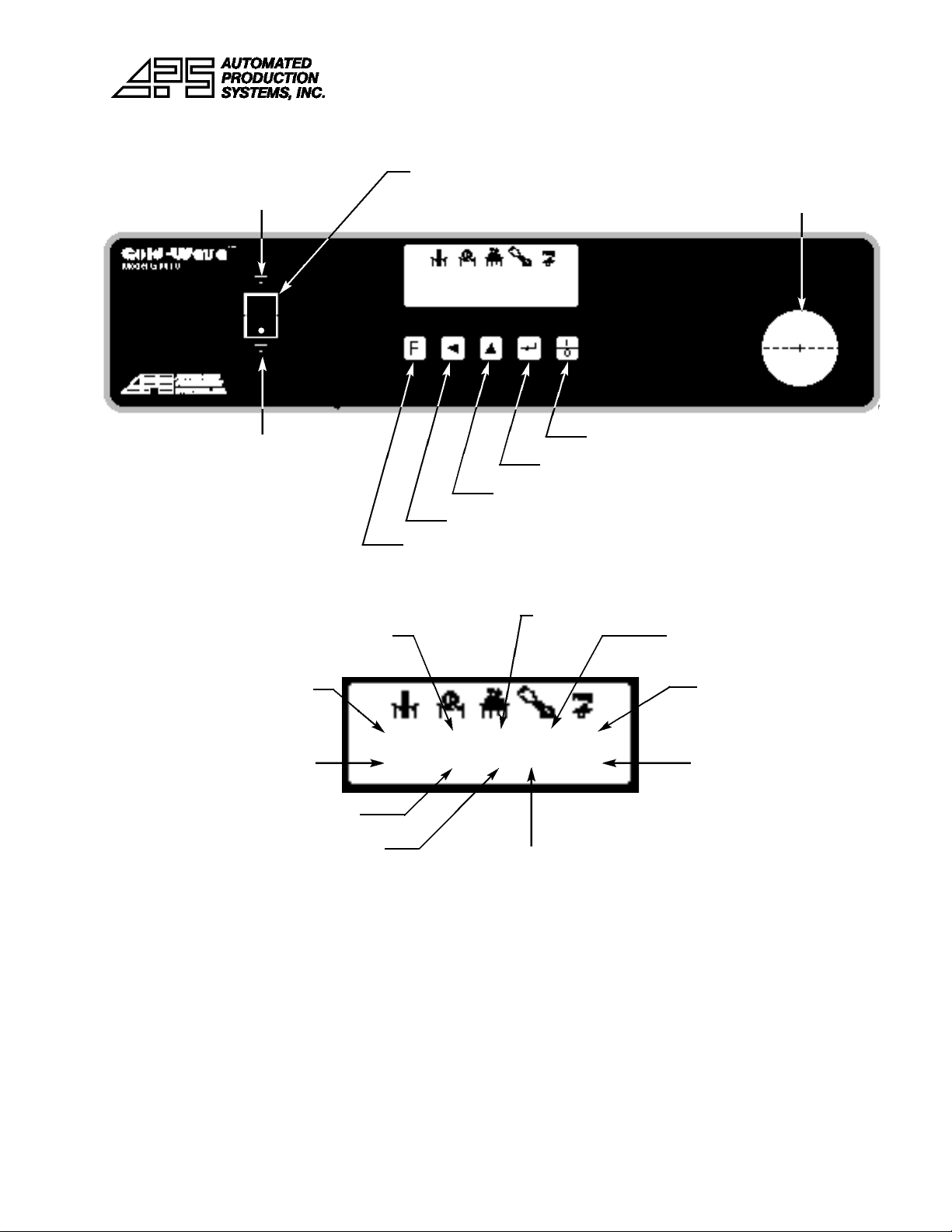
B. Ensure laser light locator is centered in wave nozzle
C. Enter program # desired (in edit mode)
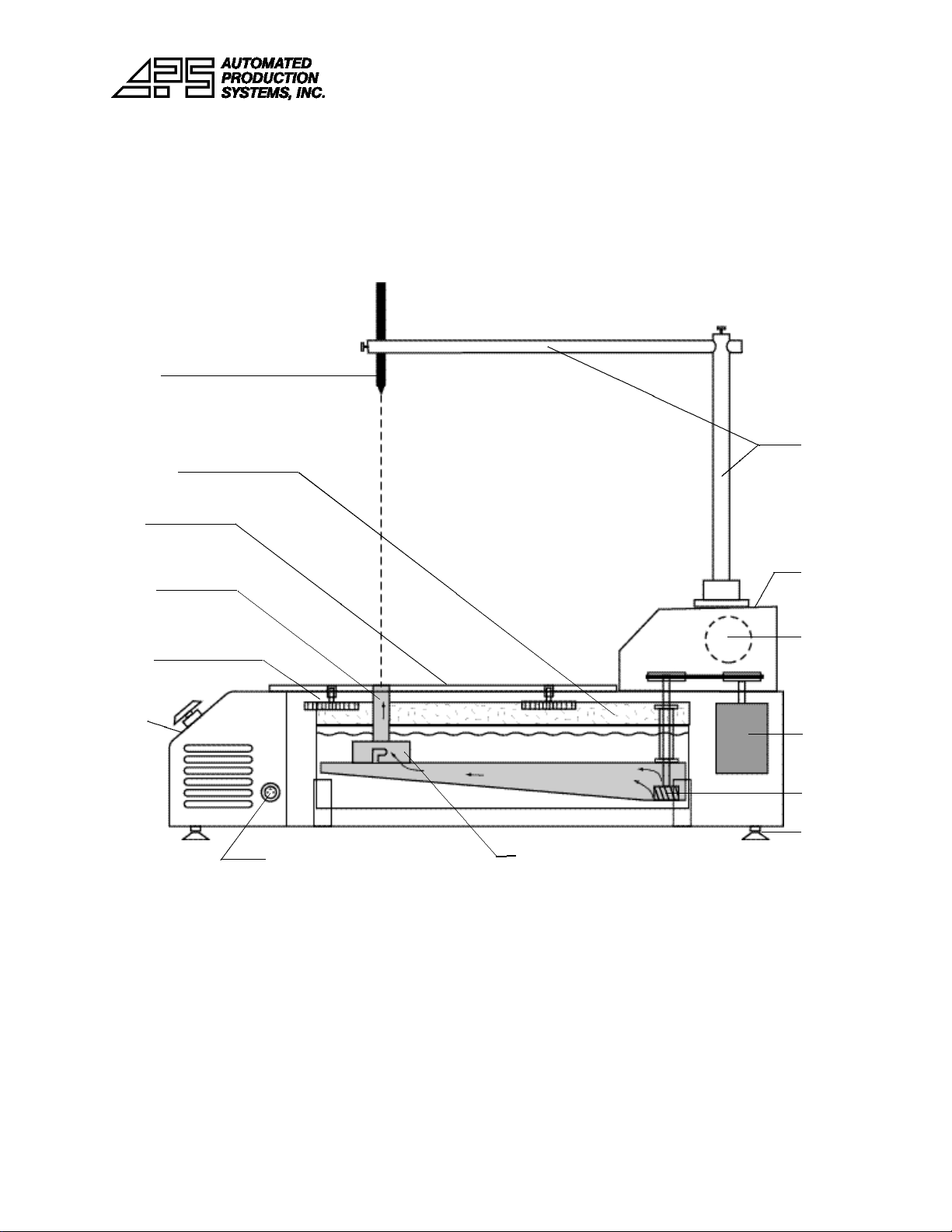
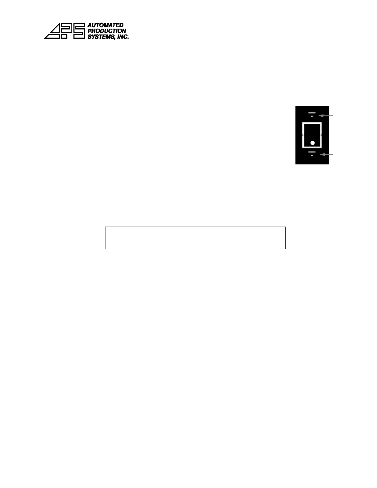
D. Ensure position switch is in Remove (down) position (see fig. 4)
E. Press foot pedal and wave will activate for wave time indicated
F. Remove component with tweezers while wave is activated
G. (For GW-10A only, machine with blowoff feature):
1. Press position switch to Insert (up) position (see fig. 4)
2. Place blowoff nozzle flush onto holes on board
3. Press foot pedal and nozzle will activate for blowoff time indicated
4. Remember to press position switch back to Remove (down) position
before next step
H. Press foot pedal and insert part while wave is active (apply flux if required)
I. Remove board to let solder joint cool
IX. SHUTDOWN
CAUTION: After turning off main power, leave unit plugged in for 1 hour
minimum to cool unit.
A. Turn main power OFF at rear of unit. Last program will be saved for next startup.
X. MAINTENANCE
A. Solder Surface:
As a natural result of oxidation, a film of oxide (dross) will appear on the sur-
face of the solder. The oxide film protects and inhibits further oxidation of the
solder. But the accumulation of too much dross is not desirable.
Remove this dross daily using a stainless steel spoon or ladle. After removing
the dross, restore solder to correct level by adding solder bars to the pot.
B. Solder Quality:
In time the solder may become contaminated. Check the solder annually or
more frequently if necessary. A small sample may be sent to your local solder
supplier or to a qualified lab for analysis.
To remove copper contamination from solder, set the solder pot temperature to
369°F (187°C) and keep it ON for 8 hours. Excess copper-rich solder can be
skimmed off from the top of the solder. For better results repeat this procedure
2-3 times.
Note: This procedure applies only to eutectic tin/lead alloy (Sn63/Pb37).
NOTE: If you have no blowoff option, always leave
position switch in the remove position.
position switch
Insert
Remove

-9-
XI. TROUBLESHOOTING SOLDERABILITY
If all variables and parameters which lead to good solderability are not properly
controlled, some typical defects will occur. The description and causes of some
common defects are listed below.
1. Poor Wetting:
Wetting is the primary factor in achieving good solder joints. A condition
when the surfaces to be joined are only partially covered with molten solder,
leaving areas of unwetted surfaces, behind is called non-wetting or poor wetting.
It shows up as pin holes and areas of bare copper or insufficient solder on
the surface of the parts to be soldered. There is virtually no adherence of the
solder.
2. De-wetting:
This condition is similar to poor wetting. It differs in that the areas to which
the solder does not adhere results from the solder pulling back from the
surfaces prior to solidifying.
3. Disturbed Joint:
When components move in relation to PCB during the solidification stage
disturbed joints are formed.
4. Excess Solder:
This condition occurs when too much solder remains on the joint. Excess
solder joints have solder fillets which appear round and fat.
5. Icicling:
Icicling is excess solder which solidifies during the peel-back stage. An icicle
has a fillet shape which appears conical and ends in a sharp point.
6. Solder Webbing:
When solder adheres to the solder mask between the metallization, it is
called solder webbing. The surface leaves thin lines of solder which form a
pattern resembling a net or web.
7. Pinholes and Blowholes:
Small holes are seen on the solder fillet. The bigger ones are called blow
holes and the smaller ones pinholes. A pinhole often conceals a much larger
internal cavity.
8. Bridging:

-10-
Bridging occurs when excess solder shorts two adjacent pads, conductors or
leads.
XII. TROUBLESHOOTING MACHINE
Failure Corrective Measures
Solder does not melt Check the circuit breaker, solid state relays
and heaters. If the circuit breaker is
tripped, turn it on. If the SSR is fused,
replace it. If the heater is burned, replace it.
Solder takes too long to melt Check heater elements. Replace defective
one.
Pre-set temperature is Check heater elements, replace defective
not achieved one.
No solder wave If solder is molten and has reached the
preset temperature, then check the solder
pump and motor.
Solder motor not running Check voltage to the motor. Check the
relevant SSR and circuit breaker. Replace
the SSR and/or turn on the circuit breaker,
if tripped.
Check belt tension. Reduce belt tension if
too tight.
If motor is running with no solder wave
then motor pulley or pump pulley may be
loose. Tighten set screw.
Impeller escaped from Remove the pump and reinstall impeller.
pump shaft
Low solder wave Check solder level. Check for clogged
pump impeller fins. Dross or any other for-
eign objects such as components may
have fallen in solder. Remove pump and
clean the impeller fins. Check belt tension
and increase if too slack.

-11-
Fig. 6 (See electrical schematics for details)
Controller board Emergency stop
Position switch
Transformer
To thermocouple
Solder pump
control SSR for
heaters Terminal block

1. Mount UBF using 4 mounting screws
2. Slide 2 sheet metal covers in from front of machine on either side of nozzle
3. Ad ust paths using thumb screws to position PC board between fingers
4. Operate machine using GW-10 operating manual
GW-UBF
Mounting Screws (4)
Finger
Thumb Screws
Path

-12-
Adjusting Nitrogen Flow
1. Supply nitrogen at 60 psi (4 bars)
2. Machine must be heated up to soldering temperature
3. Close N2standby valve completely by inserting flat screwdriver and turning clockwise
4. Open flow meter valve fully by turning flow meter knob counterclockwise
5. Adjust N2 standby valve by turning screwdriver counterclockwise until desired N2 standby
rate appears on flow meter
6. Press foot pedal to operate solder wave & adjust flow meter valve to desired soldering N2rate
N2standby valve
N2IN
flow meter knob
For GW-10/10A with Nitrogen Option

-13-
GW-10 SPARE PARTS LIST
BASE UNIT
GW-10-MB main control board
GW-10-CO controller overlay
GW-10-PM pump motor
GW-10-PB pump bearing
GW-10-HP high pressure pump assembly
GW-10-MP motor pulley
GW-10-FAN cooling fan
GW-10-CORD AC cord
GW-10-BLT belt
GW-10-SPT solder pot
GW-10-HTR heating element
GW-10-HW heater wire assembly complete
GW-10-PI pump impeller assembly w/pump pulley
GW-10-BHP board holder plate
GW-10-BHAK board holder adjustment knobs (4)
GW-10-T/C thermocouple
GW-10-LF leveling feet (4)
GW-10-FP foot pedal
GW-10-LLL laser light locator
GW-10-LLA laser locator assembly
GW-10-TRN transformer
GW-10-SPC solder pump control
GW-10-SSR solid state relay
GW-10-TB terminal block
GW-10-SWITCH position switch
GW-10-ES emergency stop switch
GW-10-UBF universal board fixture (option)
GW-10-BTA blow-thru air nozzle assembly ( option GW-10A)
GW-10-ASV air solenoid valve (option GW-10A)
WAVE NOZZLES
WN-10 1.00” x 0.50” (25 x 13 mm)
WN-20 1.50” x 0.75” (38 x 19 mm)
WN-30 2.50” x 0.75” (64 x 19 mm)
WN-40 1.00” x 1.00” (25 x 25 mm)
WN-50 1.50” x 1.50” (38 x 38 mm)
WN-60 2.00” x 2.00” (50 x 50 mm)
WN-70 2.75” x 0.35” (70 x 9 mm)
WN-80 4.00” x 0.75” (102 x 19 mm)
AIR NOZZLES FOR GW-10A ONLY
AN-10 1.00” x 0.50” (25 x 13 mm)
AN-20 1.50” x 0.75” (38 x 19 mm)
AN-30 2.50” x 0.75” (64 x 19 mm)
AN-40 1.00” x 1.00” (25 x 25 mm)
AN-50 1.50” x 1.50” (38 x 38 mm)
AN-60 2.00” x 2.00” (50 x 50 mm)
AN-70 2.75” x 0.35” (70 x 9 mm)
AN-80 4.00” x 0.75” (102 x 19 mm)


This manual suits for next models
1
Table of contents