Weller WXR 3 User manual

1
2
3
4
Equipotential bonding
Mains fuse
USB port
Interface
USB COM 1
43
COM 2
41 2
Gedruckt durch: Lochu am: 27.5.2014

Air connection nipple for
hot air tools
6
5
Pick
Up 1
Air Vac Pick Up ¬
Pick Up ¬
65 6
Pick
Up 2
UP /
DOWN
6
7
Gedruckt durch: Lochu am: 27.5.2014
7
Vacuum connection
Vacuum LED

1 Actual temperature / nominal
temperature
2
3
4
33
Nominal temperature
Fixed temperature
Active channel
2 1
4

2 CH 1, 2, 3
Switching output indicator
5
7
8
6
1 5
5
5 7 66
8
Interface COM 1 / COM 2
WFV 60A
Status indication
DATA LOGGER (DL) active
1
COM 1 COM 2

EN
For your safety
Thank you for the condence you have shown in
buying this device.
The device has been manufactured in accordance
with the most rigorous quality standards which ensu-
re that it operates perfectly.
Read these instructions and the
accompanying safety information
carefully before starting up the device
and starting work with the device.
Keep these instructions in a place that is acces-
sible to all users.
These instructions contain important information
which will help you to start up, operate and service
the device safely and correctly as well as to eliminate
simple faults and malfunctions yourselves.
The device has been manufactured in accordance
with state-of-the-art technology and acknow-
ledged regulations concerning safety.
There is nevertheless the risk of personal injury and
damage to property if you fail to observe the safety
information set out in the accompanying booklet and
the warnings given in these instructions.
Safety information
For safety reasons, children
and youths under the age of 16,
as well as persons who are not
familiar with these operating inst-
ructions, may not use the device.
Children should be supervised in
order to ensure that they do not
play with the tool.
This device is not intended
for use by persons (including
children) with limited physical,
sensory or mental aptitude, or
by persons who lack knowledge
or experience in handling the
device.
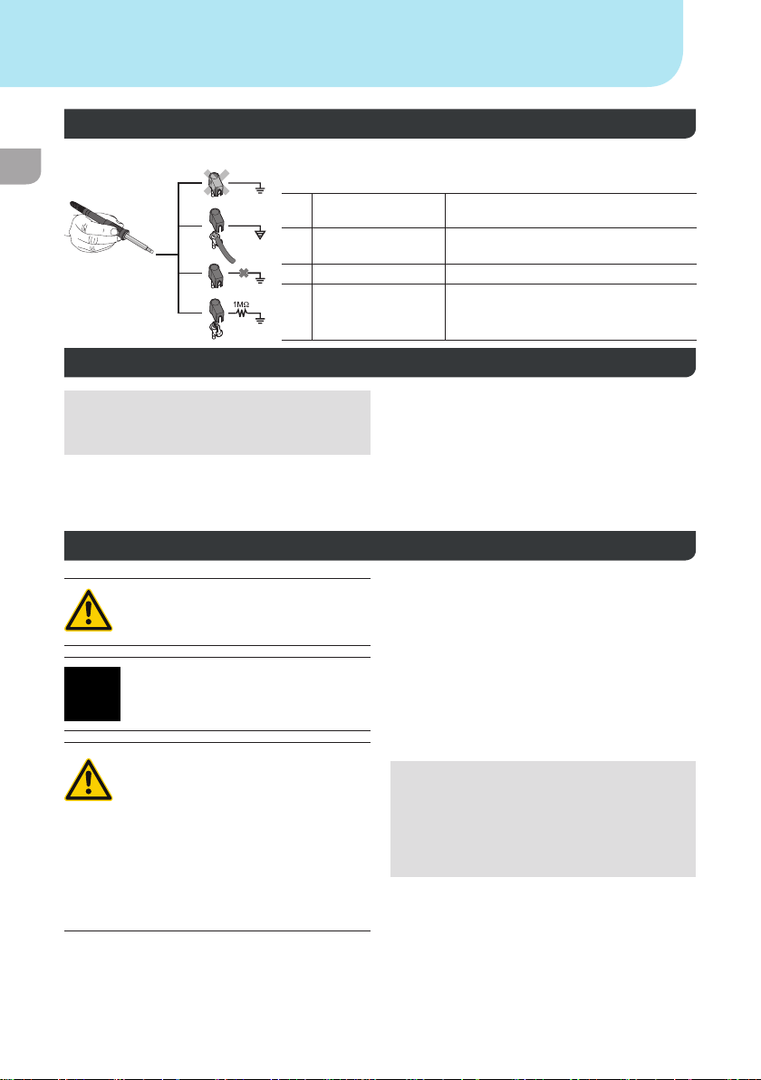
Warning! Electrical shock
Connecting the control unit incorrectly poses a risk of injury due to electric shock and
can damage the device.
Carefully read the attached safety information, the safety information accompanying these
operating instructions as well as the operating instructions for your control unit before putting
the control unit into operation and observe the safety precautions specied therein.
Only connect WELLER WX tools.
Never use the USB port as a power supply for third-party devices.
If the device is faulty, active electrical conductors may be bare or the PE conductor
may not be functional.
Repairs must always be referred to a Weller-trained specialist.
If the electrical tool‘s power supply cord is damaged, this must be replaced with a specially
prefabricated power supply cord available through the customer service organisation.
Warning! Risk of burns
Risk of burns from the soldering tool while the control unit is operating. Tools may
still be hot long after they have been switched off.
Always place the soldering tool in the safety rest while not in use.
Only connect the vacuum and hot air at the designated points.
Do not direct hot air soldering tools at people or inammable objects.

EN
Warning! Fire and explosion hazard!
Hot tools represent a re hazard
Always place the soldering tool in the safety rest while not in use.
Do not direct hot air soldering tools at people or inammable objects.
Keep explosive and ammable objects well away from the device.
Do not cover the device.
Specied Conditions Of Use
Supply unit for WELLER WX soldering tools.
Use the repair station only for the purpose indica-
ted in the operating instructions of soldering and
desoldering under the conditions specied herein.
Flammable gases and liquids may not
be extracted.
The device may only be used with
correctly tted and suitable lter
cartridges.
Replace lter cartridges when full.
Only use the device indoors. Protect against mois-
ture and direct sunlight.
Intended use of the soldering station/ desoldering
station also includes the requirement that you
adhere to these instructions,
observe all other accompanying documents,
comply with national accident prevention
guidelines applicable at the place of use.
The manufacturer will not be liable for unautho-
rised modications to the device.
User groups
Due to differing degrees of risk and potential hazards, several work steps may only be performed by
trained experts.
Work step User groups
Default soldering parameters Specialist personnel with technical training
Replacing electrical replacement parts Electricians
Default maintenance intervals Safety expert
Operation
Filter change
Non-specialists
Operation
Filter change
Replacing electrical replacement parts
Technical trainees under the guidance and supervision
of a trained expert
For your safety

EN
Starting up the device
Caution!
Please adhere to the operating instructions of
the connected devices.
Put the tool into operation as described in the
chapter „Placing into operation“.
Check to see if the mains voltage mat-
ches the ratings on the nameplate.
Make sure the machine is switched off before
plugging in.
After switching on the device, the microprocessor
carries out a self- test and reads out the values of
the parameters stored in the tool.
The set-point temperature and xed temperatures
are stored in the tool. The actual temperature
value increases to the set-point temperature (=
soldering tool is heated up).
Soldering and desoldering
Carry out soldering work as directed in the opera-
ting instructions of your connected soldering tool.
Handling the soldering tips
Coat the selective and tinnable soldering tip with
solder when heating it up for the rst time. This
removes oxide coatings which have formed
during storage and impurities from the soldering
tip.
Make sure that the soldering tip is well coated
with solder during breaks between soldering work
and prior to storage of the device.
Do not use aggressive uxing agents.
Always make sure that the soldering tips are
tted properly.
Select as low a working temperature as possible.
Select the largest possible soldering tip shape for
the application.
Rule of thumb: the soldering tip should be roughly
as large as the soldering pad.
Coat the soldering tip well with solder to ensure
that there is efcient heat transfer between the
soldering tip and the soldering area.
Prior to extended breaks between soldering work,
switch off the soldering system or use the Weller
function to reduce the temperature when the
soldering equipment is not in use.
Coat the tip with solder prior to storage if you do
not intend to use the soldering iron for an
extended period of time.
Apply solder directly to the soldering area, not to
the soldering tip.
Change the soldering tips using the designated
tool.
Do not apply mechanical force to the soldering
tip.
Notice
The control units have been adapted to hold a
medium-sized soldering tip. Discrepancies may
occur if the tip is changed or a different shaped
tip is used.
Overload cut-out
To avoid overloading the station, power output is
automatically reduced in the event of an overload.
For your safety

EN
Equipotential bonding
a
b
c
d
Four variants are possible by connecting the 3.5 mm jack socket
differently:
a Hard-grounded supplied without plug.
b Equipotential
bonding
with plug, equaliser at centre contact.
c Floating with plug
d Soft-grounded with plug and soldered resistor. Ground-
ed through selected resistor.
Carrying out a rmware update
Notice
The station must not be switched off while the
rmware update is running.
Switch off station 1.
2. Insert the memory stick into the USB port.
Switch on station 3.
The rmware update is performed automatically.
If you have a more already installed more recent
rmware on your station, this will not be changed.
Care and maintenance
Warning!
Before doing any work on the machi-
ne, pull the plug out of the socket.
Warning!
Use original replacement parts only.
Warning! Risk of burns
Only replace solder tips when cold
Replace and clean suction nozzles
only when hot and using the suitable
tool
Only replace hot air nozzles using
the suitable tool
Only clean or replace solder
collection tubes when cold
Clean the operator panel, if dirty, using a suitable
cleaning cloth.
Filter change
Check the lter regularly for contamination, and
replace it if necessary.
Warning!
Failure to use a lter will cause irreparable dama-
ge to the vacuum pump.
Check before starting soldering whether a main
lter is inserted.
Contaminated lters must be treated as special
waste.
Dispose of replaced equipment parts, lters
or old devices in accordance with the rules
and regulations applicable in your country.
Wear suitable protective gear.
For your safety

EN
Standby Temp. Menu access Tool parameters
The soldering tools have a usage detection device
(sensor) in the handle which automatically initiates
cooling to Standby temperature when the solde-
ring tool is not in use.
Standby time (temperature deactivation) Menu access Tool parameters
When the soldering tool is not in use, the tem-
perature is reduced to Standby temperature on
expiration of the set Standby time. The display
reads „Standby“.
Press control key to exit Standby mode. The
sensor integrated tool detects the change in state
and deactivates Standby mode as soon as the tool
is moved.
Option Description
OFF standby time is deactivated (factory
setting)
1-999 min standby time, individually adjustable
--- The tool is not supported
AUTO OFF time (automatic switch-off time) Menu access Tool parameters
When the soldering tool is not in use, the soldering
tool heater is switched off when the AUTO OFF
time expires.
Temperature deactivation is performed indepen-
dently of the set standby function. The actual
temperature is indicated and serves as a residual
heat display. The display reads „AUTO OFF“.
Option Description
OFF AUTO OFF function is deactivated
(factory setting)
1-999 min AUTO-OFF time, can be set indivi-
dually.
Sensitivity Menu access Tool parameters
Option Description
low Non-sensitive – Reacts to heavy (long) movement
normal standard (factory setting)
high Sensitive - Reacts to light (short) movement
--- The tool is not supported
Max. hot air duration WXHAP Menu access Tool parameters
The on-time of the hot air ow of the WXHAP can
be limited in increments of 1 to between 0 and 300
sec. The factory default is 0 s („OFF“), i.e. air ows
only as long as the button on the hot air tool or the
optional footswitch is pressed.
Option Description
OFF No duration dened
(factory setting)
1-300 s Individually adjustable
Offset (Temperature-Offset) Menu access Tool parameters
The actual soldering-tip temperature can be
adapted by entering a temperature offset around ±
40 °C (± 72 °F).
Parameter menu

EN
Parameter menu
Perform. Mode Menu access Tool parameters
The function determines the heating characteris-
tics of the soldering tool to achieve the set tool
temperature.
Option Description
standard adapted (medium) heating (factory
setting)
min. slow heating
max. rapid heating
Button lock WXHAP Menu access Tool parameters
This function can be used to adjust the factory
button presets of the WXAHP tool. Option Description
OFF –
ON The WXHAP is switched on the rst
time the button is pressed and switched
off the next time the button is pressed.
Process window Menu access Tool parameters
The temperature range set in the process window
determines the signal response of the oating
switching output.
Notice
On tools with an LED ring light (e.g. WXDP 120),
the process window denes the illumination
characteristics of the LED ring light.
If the LED is continuously illuminated, this means
that the preselected temperature has been
reached or that the temperature is within the
predetermined process window.
A ashing LED indicates that the system is
heated or that the temperature is outside the
process window.
Language Menu access Station parameters
CHN 中文
DEN Dansk
ENG English
ESP Español
FIN Suomi
FRA Français
GER Deutsch
HUN Magyar
ITA Italiano
POR Português
RUS Pусский
SWE Svenska
TUR Türkçe
JPN 日本語
POL Polski
KOR 한국말
CZE Český
Temperature version °C/°F (temperature units) Menu access Station parameters
Option Description
°C Celsius
°F Fahrenheit

EN
Parameter menu
Password (lock function) Menu access Station parameters
After switching the lock function on, only the xed
temperature keys can be operated on the solde-
ring station. All other settings are disabled until the
repair station is unlocked again.
Notice
If you want only one temperature value to be
selectable, the control keys xed temperature
keys) must be set to the same temperature value.
Locking the soldering station
Set the desired three-digit locking code (between
001 and 999) using the UP / DOWN buttons.
Conrm the code with the Enter key.
The lock is active (the display shows a lock
symbol).
Unlocking the soldering station
1. Call up the parameter menu. If the lock function
is active, the password menu item opens
automatically. Three stars (***) are shown on the
display.
2. Set the three-digit locking code using the UP /
DOWN buttons.
3. Confirm the code with the Enter key.
Single-channel display Menu access Station parameters
To obtain more straightforward readings, the
display mode from can switched from 3-channel
display to 1-channel display.
If single-channel display is selected, the device
does not reset automatically to 3-channel display
after setting the temperature of a tool channel.
The display mode can be reset using ┌ 2 ┐.
Option Description
OFF Automatic reset to 3-channel display
(factory setting)
ON No automatic reset to 3-channel
display
Vacuum pre-feed Menu access Station parameters
In order to prevent the pump from starting pre-
maturely or to ensure a dened soldering-joint
preheating time, it is possible to set an ON delay.
Option Description
0 sec OFF: vacuum pre-feed function is
OFF (factory setting)
1-10 sec ON: vacuum pre-feed time, indivi-
dually
Vacuum run-on Menu access Station parameters
To prevent the desoldering iron from becoming
clogged, it is possible to set a vacuum run-on time. Option Description
0 sec OFF: vacuum run-on function is OFF
(factory setting)
1-10 sec ON: vacuum run-on time, individually
adjustable

EN
Parameter menu
Pressure gauge threshold Menu access Station parameters
This function can be used to dene the mainte-
nance interval of the desoldering tool. This is done
by setting the value in mbar at which the electric
pressure gauge issues a warning signal when the
intake system is contaminated (LED of the vacuum
pump switches from green to red). The set value is
dependent on the suction nozzles used.
Adjustable -400 mbar to -800 mbar
factory setting -600 mbar
1. The system (tips and lter) must be free.
2. Select the menu item „Pressure gauge
threshold“ in the menu.
3. Set the „Pressure gauge threshold“ pressure
value with the UP or DOWN button. The status
LED switches back and forth between red and
green. Use the UP button to increase vacuum
by 50 to 80 mbar, then pinch the vacuum tube
and check whether the LED switches from
green to red.
4. Adopting the set change.
Interface COM 1 / 2 Menu access Station parameters
Option Description
RS232 Serial communication with PC or other compatible Weller devices (factory setting).
Air The COM 1 port is congured as a foot switch input for activating the air ow.
Vac The COM 1 port is congured as a foot switch input for activating the vacuum.
PickUp The COM 1 port is congured as a foot switch input for activating the PickUp vacuum.
Stop&Go The COM 1 port is used to drive an optional optotransmitter so that a KHE-P control
unit can be activated via an optical bre.
The output is activated when a tool is used. In addition, the oating switched output is
closed. The output is off in the Standby, Auto Off or Off positions, or if no tool is inserted.
Floating switching output 1 Menu access Station parameters
Floating switching output 1 is located at the COM 1 port.
Option Description
OFF (factory setting)
ZeroSmog The oating switching output is closed when a tool is in use. Selected Zero Smog
extraction systems can be connected using an optional adaptor (WX HUB). The rear
RS 232 port remains functional.
Switching output is open in the Standby, Auto Off or Off positions, or if no tool is inser-
ted.
Notice
If the COM 1 port is also congured for „Stop&Go“ use, the „Filter full“
message is evaluated by the WX HUB and, where applicable, a
message appears on the display .

EN
Parameter menu
Floating switching output 2 Menu access Station parameters
Floating switching output 2 is located at the COM 2 port.
Option Description
OFF (factory setting)
CH 1 Tool channel 1 controls the switching output
CH 1+2 Tool channel 1 + 2 controls the switching output
CH 1+2+3 Tool channel 1 + 2 + 3 controls the switching output
Notice
If the robot is at working temperature, the display will show – ok –.
Technical Data
Repair station WXR 3
Dimensions L x W x H 273 x 235 x 102 mm
(10,75 x 9,25 x 4,02 inch)
Weight ca. 6,7 kg
Mains supply voltage 230 V, 50 Hz T0053500699
120 V, 60 Hz WXR 3
100 V 50/60 Hz T0053500199
Power consumption 420 W (600 W)
Safety class I, antistatic housing
III, Soldering tool
Fuse Overcurrent release 230 V; 2,0 A
120 V; 4,0 A
Temperature range Celsius: 100 - 450°C (550°C)
Fahrenheit: 200 - 850°F (999°F)
Controllable temperature range is tool-dependent
Temperature accuracy ± 9 °C (± 17 °F) Tool dependent (WXHAP 200 ±30 °C / ±80 °F)
Temperature stability ± 2 °C (± 4 °F)
Equipotential bonding Via 3.5 mm pawl socket on back of unit
Display 240 x 88 dots / Backlighting
USB port The control unit comes with a USB port for installing rmware updates,
conguration and monitoring.
Pump (Intermittent mode
(30/30) s)
Max. vacuum 0,7 bar
Max. delivery rate 18 l/min
Max. hot air 15 l/min
Additional vacuum pump Max. vacuum0,5 bar
Max. delivery rate 1,7 l/min

EN
Message/symptom Possible cause Remedial measures
Display: „- - -
Tool has not been detected
Tool defective
Check connection of tool to
device
Check connected tool
No display function (display
OFF)
No mains supply voltage Turn on mains power switch
Check mains supply voltage
Check device fuse
No vacuum at desoldering tool
Vacuum not connected
Desoldering nozzle clogged
Pump faulty
Connect vacuum hose to
vacuum connection
Service desoldering nozzle
using cleaning tool
Insufcient vacuum at desolde-
ring tool
Filter cartridge on desoldering
tool full
Main lter full
Change lter cartridge on
desoldering tool full
Change the main lter element
on the soldering station
Hot air tool has no air
Air hose not connected
Main lter full
Connect or check air hose
Change main lter cartridge on
soldering station
Symbols
Caution!
Read the operating instructions!
Before performing work of any kind
on the unit, always disconnect the
power plug from the socket.
ESD-compatible design and ESD-
compatible workstation
Equipotential bonding
CE mark of conformity
Fuse
Safety transformer
Soldering
Desoldering
Hot air
Disposal
Do not dispose of electric tools together
with household waste material! In
observance of European Directive
2012/19/EU on waste electrical and
electronic equipment and its implemen-
tation in accordance with national law,
electric tools that have reached the end
of their life must be collected separately
and returned to an environmentally
compatible recycling facility.
Dispose of replaced equipment parts,
lters or old devices in accordance with
the rules and regulations applicable in
your country.
Error messages and error clearance

EN
Original declaration of conformity
Repair station WXR 3
Tool WXHAP 200, WXDP 120, WXDV 120, WXP 65, WXP 120,
WXP 200, WXMP, WXMT, WXSB 200, WXHP 120
We hereby declare that the products described herein comply with the following guidelines:
2011/65/EU (RoHS), 2004/108/EG, 2006/42/EG
Applied harmonised standards:
DIN EN 55014-1: 2012-05 DIN EN 60335-1: 2012-10
DIN EN 55014-2: 2009-06 DIN EN 60335-2-45: 2012-08
DIN EN 61000-3-2: 2010-03 / 2011-06 DIN EN 62233: 2008-11 / 2009-04
DIN EN 61000-3-3: 2014-03 DIN EN 50581:2013-02
Besigheim, 2015-07-08
T. Fischer S. Hofmann
Technical director Managing director
Authorised to compile technical documentation.
Weller Tools GmbH
Carl-Benz-Straße 2, 74354 Besigheim, Germany
Warranty
Claims by the buyer for physical defects are time-
barred after a period of one year from delivery to
the buyer. This does not apply to claims by the
buyer for indemnication in accordance with §§
478, 479 BGB (German Federal Law Gazette).
We shall only be liable for claims arising from a
warranty furnished by us if the quality or durability
warranty has been furnished by use in writing and
using the term „Warranty“.
The warranty shall be void if damage is due to impro-
per use and if the device has been tampered with by
unauthorised persons.
Subject to technical alterations and amendments.
Other manuals for WXR 3
5
This manual suits for next models
2
Table of contents
Other Weller Rework Station manuals

Weller
Weller WR 2 User manual

Weller
Weller WQB 3000 Safety guide

Weller
Weller WQB 4000SOPS User manual

Weller
Weller WQB 4000SOPS User manual

Weller
Weller WR 2 User manual

Weller
Weller WXR 3 User manual

Weller
Weller WRK User manual

Weller
Weller WQB 4000SOPS Operator's manual

Weller
Weller WR 3ME User manual

Weller
Weller WXR 3 User manual