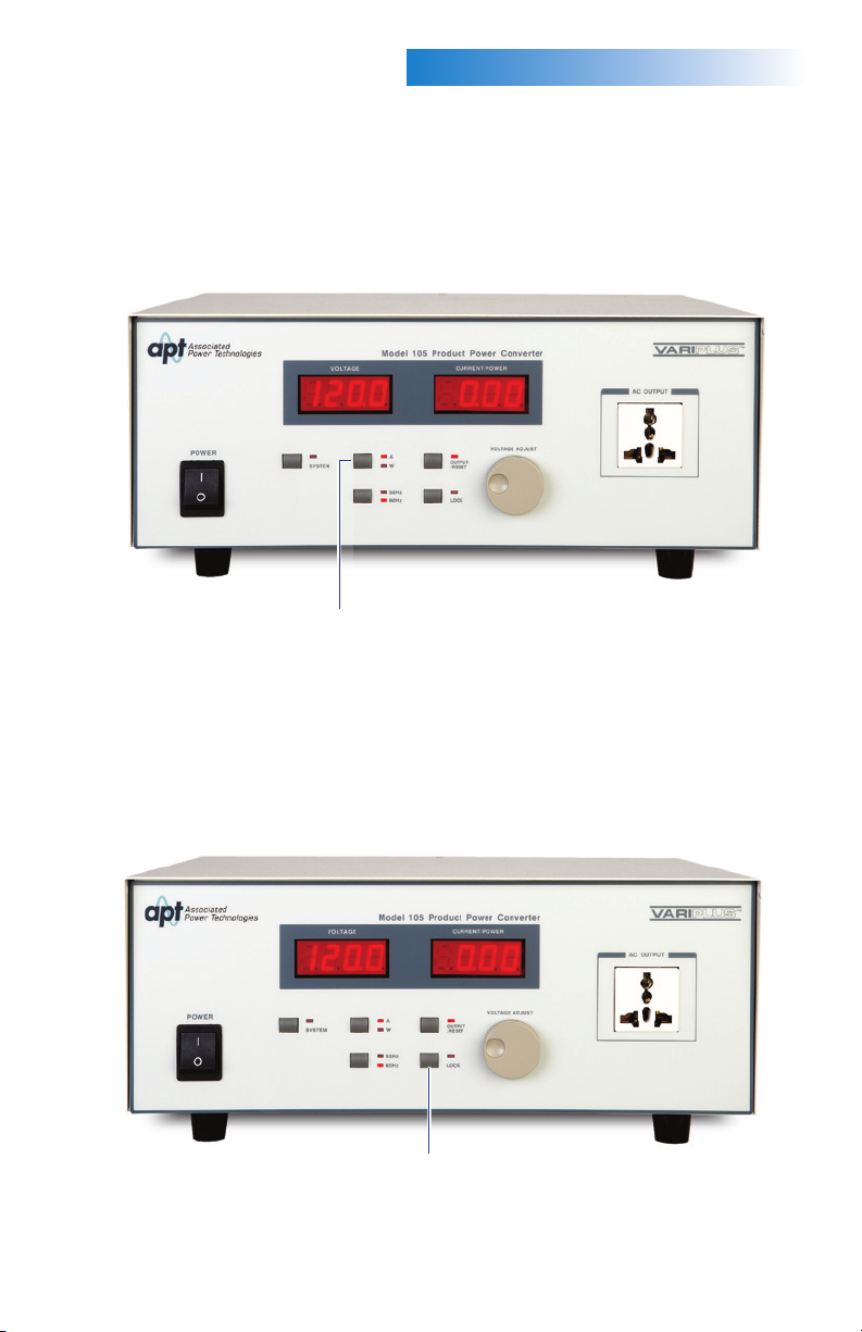
SETTING THE OUTPUT/RESET:
Press the OUTPUT/RESET key to set the output. If the LED indicator is lit, the decimal
points in the displays of voltage and current/power will blink continuously notifying the
operator that output is ON. If the LED indicator is not lit and the decimal points in the
displays of voltage and current/power are lit steadily this indicates that the output is
OFF. When the output is OFF the displays will show their present settings.
If the Output/Reset LED indicator is flashing, this is a notification that a limit threshold
has been exceeded, a failure has occurred, or an instrument protection circuit has been
activated. Press the OUTPUT/RESET key to reset the instrument to a normal state.
Press the SYSTEM key to change the system parameters. The LED indicator will be on
when the SYSTEM key is activated. The SYSTEM key is only available if the output is off
or the LED indicator is off on the OUTPUT/RESET key. Press the SYSTEM key to cycle
through the parameters. Use the rotary knob to adjust the system parameter settings.
5.
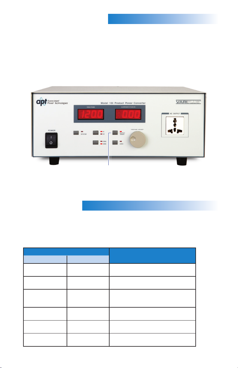
INSTRUMENTSETUP
SYSTEMSETUP
Output/Reset key
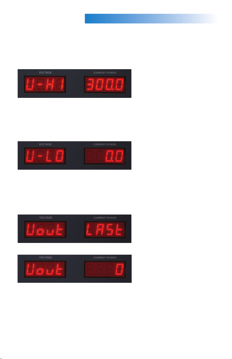
DISPLAY EXPLANATION
Voltage Current
V-HI 300.0 High voltage limit setting (0.0 – 300.0 V),
0.0 disables feature
V-LO 0.0 Low voltage limit setting (0.0 – 300.0 V),
0.0 disables feature
Vout LAST Output is set to voltage based on last
setting prior to power off when the
instrument is powered up
Vout 0 Output is 0 volts when the instrument is
powered up
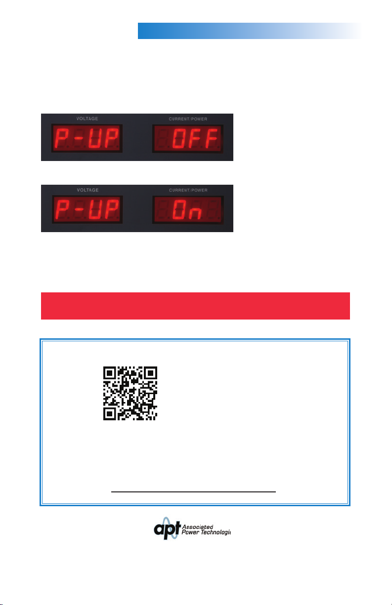
P-UP OFF Output relay is open when the instrument
is powered up
P-UP ON Output relay is closed when the instrument
is powered up