manuals.online logo
Brands
  1. Home
  2. •
  3. Brands
  4. •
  5. APW Wyott
  6. •
  7. Grill
  8. •
  9. APW Wyott HCB-2424 User manual

APW Wyott HCB-2424 User manual

This manual suits for next models

9

Other APW Wyott Grill manuals

APW Wyott HOTROD HR-45 User manual

APW Wyott

APW Wyott HOTROD HR-45 User manual

APW Wyott HOTROD User manual

APW Wyott

APW Wyott HOTROD User manual

APW Wyott HR-31E User manual

APW Wyott

APW Wyott HR-31E User manual

APW Wyott HR-20 User manual

APW Wyott

APW Wyott HR-20 User manual

APW Wyott HOTROD User manual

APW Wyott

APW Wyott HOTROD User manual

APW Wyott HR-20 User manual

APW Wyott

APW Wyott HR-20 User manual

APW Wyott TG-2025 User manual

APW Wyott

APW Wyott TG-2025 User manual

APW Wyott HR-31E User manual

APW Wyott

APW Wyott HR-31E User manual

APW Wyott TBTGIL User manual

APW Wyott

APW Wyott TBTGIL User manual

APW Wyott Slanted HOTROD User manual

APW Wyott

APW Wyott Slanted HOTROD User manual

APW Wyott HR-20 User manual

APW Wyott

APW Wyott HR-20 User manual

APW Wyott HR-20S User manual

APW Wyott

APW Wyott HR-20S User manual

APW Wyott HRS-75 5T User manual

APW Wyott

APW Wyott HRS-75 5T User manual

APW Wyott TBTGIL User manual

APW Wyott

APW Wyott TBTGIL User manual

APW Wyott Champion GCB-18H User manual

APW Wyott

APW Wyott Champion GCB-18H User manual

APW Wyott Champion GCB-18H User manual

APW Wyott

APW Wyott Champion GCB-18H User manual

Popular Grill manuals by other brands

LMS BBQ08873P owner's manual

LMS

LMS BBQ08873P owner's manual

Cookworks LW-8010A Care & instruction manual

Cookworks

Cookworks LW-8010A Care & instruction manual

Campingaz CV Instructions for use

Campingaz

Campingaz CV Instructions for use

Metos XBL Series Installation and operation manual

Metos

Metos XBL Series Installation and operation manual

Fiesta ET34567 Use and care instructions

Fiesta

Fiesta ET34567 Use and care instructions

Mayer Barbecue BRENNA MKG-318A BASIC Assembly instructions

Mayer Barbecue

Mayer Barbecue BRENNA MKG-318A BASIC Assembly instructions

Landmann Avalon PTS Plus 5.1 Plus 12122 Assembly and operating manual

Landmann

Landmann Avalon PTS Plus 5.1 Plus 12122 Assembly and operating manual

Kenyon B70200 owner's manual

Kenyon

Kenyon B70200 owner's manual

Better Homes and Gardens GBC1486W owner's manual

Better Homes and Gardens

Better Homes and Gardens GBC1486W owner's manual

Orbegozo GR 2300 instruction manual

Orbegozo

Orbegozo GR 2300 instruction manual

bora PT11 Operating and installation instructions

bora

bora PT11 Operating and installation instructions

Klarstein 10031664 manual

Klarstein

Klarstein 10031664 manual

Garland MWE3W Installation and operation manual

Garland

Garland MWE3W Installation and operation manual

Char-Broil 463722714 Product guide

Char-Broil

Char-Broil 463722714 Product guide

MPM MOP-03 user manual

MPM

MPM MOP-03 user manual

Kenmore 415.16123800 Use and care guide

Kenmore

Kenmore 415.16123800 Use and care guide

Tucker Barbecues GTR Series Assembly, installation and operating instructions

Tucker Barbecues

Tucker Barbecues GTR Series Assembly, installation and operating instructions

Monogram ZGG540NCP1SS owner's manual

Monogram

Monogram ZGG540NCP1SS owner's manual

manuals.online logo
manuals.online logoBrands
  • About & Mission
  • Contact us
  • Privacy Policy
  • Terms and Conditions

Copyright 2025 Manuals.Online. All Rights Reserved.

INSTALLATION
AND
OPERATING
INSTRUCTIONS
P/N 8835300 2-09
1
Heavy Duty Radiant Gas Char-Broilers
MODELS: HCB-2424, HCB-2436, HCB-2448, HCB-2460, HCB-2472
&
Please complete this information and retain this manual for the life of the equipment. For
Warranty Service and/or Parts, this information is required.
Model Number Serial Number Date Purchased
IMPORTANT FOR FUTURE REFERENCE
FOR YOUR SAFETY: Do not store or use gasoline or other flammable vapors or liquids
in the vicinity of this or any other appliance.
WARNING: Improper installation, adjustment, alteration, service or maintenance can
cause property damage, injury or death. Read the installation, operating and
maintenance instructions thoroughly before installing, or servicing this equipment.
WARNING: Instructions must be posted in a prominent location. All safety precautions
must be taken in the event the user smells gas. Safety information can be obtained from
your local gas supplier.
LISTED
GAS-FIRED
US
CUL
ANSI/NSF4
UL
EPH
APW Wyott Foodservice Equipment Company
Heavy Duty Lavarock Gas Char-Broilers
MODELS: HCRB-2424, HCRB-2436, HCRB-2448, HCRB-2460, HCRB-2472
E-mail: [email protected]
www.apwwyott.com
Dallas Plant
729 Third Ave. Dallas, TX 75226
Local: 1-(214) 421-7366
Toll Free: 1-(800) 527-2100
Parts/Service Fax: 1-(214) 565-0976
Cheyenne Plant
1938 Wyott Drive, Cheyenne, WY 82007
Local: 1-(307) 634-5801
Toll Free: 1-(800) 752-0863
Parts/Service Fax: 1-(307) 772-0460
!
!
TABLE OF CONTENTS:
2
ITEM PAGE
Safety Precautions ........................................3
General Installation Instructions....................4
Specifications & Dimensions.........................4
Conversion ....................................................8
Lighting Instructions ......................................9
Operating Instructions ...................................10
ITEM PAGE
Cleaning/Maintenance ......................................11
Service/Repair ..................................................12
Troubleshooting Guide......................................12
Replacement Parts Lists & Exploded View.......13
Warranty ...........................................................20
CAUTION: These models are designed, built, and sold for commercial use. If these models
are positioned so the general public can use the equipment, make sure that cautions,
warnings, and operating instructions are clearly posted near each unit so that anyone using
the equipment will use it correctly and not injure themselves or harm the equipment.
WARNING: Improper installation, adjustment, alteration, service or maintenance can
cause property damage, injury or death. Read the installation, operating and
maintenance instructions thoroughly before installing, or servicing this equipment.
WARNING: For your safety do not store or use gasoline or other flammable vapors and
liquids in the vicinity of this or any other appliance. Keep the area free and clear of
combustibles. (See ANZI Z83. 14B, 1991).
NOTICE: Instructions to be followed if anyone smells gas should be posted in a prominent
place. These may be obtained from the gas supplier.
GAS PRESSURE
The appliance and it’s individual shutoff valve (to be supplied by user) must be disconnected from the gas
supply piping system during any pressure testing of that system at test pressures in excess of ½ psi (3.45
kPa). NOTE: Gas shutoff valve is supplied on CE models.
The appliance must be isolated from the gas supply piping system by closing it’s individual manual shut-off
valve during any pressure testing of the gas supply piping system at test pressures equal to or less than ½
psi (3.45 kPa).
WARNING: A factory authorized agent should handle all maintenance and repair. Before
doing any maintenance or repair, contact APW Wyott.
Congratulations on your purchase of APW Wyott commercial cooking or refrigeration equipment.
APW Wyott takes pride in the design and quality of our products. When used as intended and with proper
care and maintenance, you will experience years of reliable operation from this equipment. To ensure best
results, it is important that you read and follow the instructions in this manual carefully.
LOCATION OF DATA PLATE
The data plate is located on the right side panel.
3
IMMEDIATELY INSPECT FOR SHIPPING DAMAGE
All containers should be examined for damage before and during unloading. The freight carrier has
assumed responsibility for its safe transit and delivery. If equipment is received damaged, either apparent or
concealed, a claim must be made with the delivering carrier.
A) Apparent damage or loss must be noted on the freight bill at the time of delivery. It must then be signed by
the carrier representative (Driver). If this is not done, the carrier may refuse the claim. The carrier can supply
the necessary forms.
B) Concealed damage or loss if not apparent until after equipment is uncrated, a request for inspection must
be made to the carrier within 15 days. The carrier should arrange an inspection. Be certain to hold all
contents and packaging material.
Installation and start-up should be performed by a qualified installer who thoroughly read, understands and
follows these instruction.
If you have questions concerning the installation, operation, maintenance or service of this product, write
Technical Service Department APW Wyott Foodservice Equipment Company, 1938 Wyott Drive,
Cheyenne, WY 82007.
DANGER: This symbol warns of imminent hazard which will result in serious injury or
death.
WARNING: This symbol refers to a potential hazard or unsafe practice, which could result
in serious injury or death.
CAUTION: This symbol refers to a potential hazard or unsafe practice, which may result in
minor or moderate injury or product or property damage.
NOTICE: This symbol refers to information that needs special attention or must be fully
understood even though not dangerous.
NOTICE: This product is intended for commercial use only. Not for household use.
CAUTION: These models are designed, built, and sold for commercial use. If these
models are positioned so the general public can use the equipment make sure that
cautions, warnings, and operating instructions are clearly posted near each unit so that
anyone using the equipment will use it correctly and not injure themselves or harm the
equipment.
WARNING: Improper installation, operation, service or maintenance can cause property
damage, injury or death. Read and understand these instructions thoroughly before
positioning, installing, maintaining or servicing this equipment.
NOTICE: Local codes regarding installation vary greatly from one area to another. The
National Fire Protection Association, Inc., states in its NFPA96 latest edition that local
codes are “Authority Having Jurisdiction” when it comes to requirement for installation of
equipment. Therefore, installation should comply with all local codes.
SAFETY PRECAUTIONS
GENERAL INSTALLATION INSTRUCTIONS
Ensure gas supply and gas type, as shown on unit nameplate agree.
Unit installation must conform with the National Fuel Gas Code, ANSI Z223.1/NFPA 54, the National Gas
Installation Code, CSA-B149.1, or the Propane Installation Code, CSA-B149.2 as applicable and in
accordance with local codes.
Screw legs into the permanently fastened nuts on the four corners of the unit and tighten by hand. Level the
unit by turning the adjustment screw at the bottom of each leg. Do not slide unit with legs mounted, lift if
necessary to move unit.
Pipe threading compound must be resistant to the action of liquefied petroleum gases.
Caution: DO NOT use an open flame to check for leaks. Check all gas piping for leaks with a soap and water
solution before operating unit.
THESE UNITS ARE SUITABLE FOR INSTALLATION ON NON-COMBUSTIBLE SURFACES ONLY.
Noncombustible clearances:
0" sides (0 mm) 0" rear (0 mm) 4” floor (102mm)
Do not obstruct the flow of combustion and ventilation air, under the unit by the legs or behind the unit by the
flue.
Adequate clearance for air openings into the combustion chamber is required. Do not place objects between
the bottom of the unit and the counter top.
There must be adequate clearance for removal of the front panel. All major parts except the burners are
removable thru the front if the gas line is disconnected.
Unit must have adequate clearances for servicing. (Sides = 0”, Rear = 0”, Floor = 4”).
European Community Installation Instructions:
“THIS APPLIANCE MUST BE FITTED BY A COMPETENT PERSON. IN THE UK, CORGI REGISTERED
INSTALLERS (INCLUDING THE REGIONS OF BRITISH GAS) UNDERTAKE TO WORK TO SAFE AND
SATISFACTORY STANDARDS. THIS APPLIANCE MUST BE INSTALLED IN ACCORDANCE WITH THE
GAS SAFETY (INSTALLATION AND USE) REGULATIONS AND THE RELEVANT BUILDING
REGULATIONS / IEE. REGULATIONS. DETAILED RECOMMENDATIONS ARE CONTAINED IN THE
FOLLOWING BRITISH STANDARD CODES OF PRACTICE - BS 6172, BS 5440 PART 2, BS 6891"
"THIS APPLIANCE MUST BE INSTALLED IN ACCORDANCE WITH THE RULES IN FORCE”
"MUST BE INSTALLED IN A WELL VENTILATED AREA. Ventilation requirements ie. B.S. 5440.”
4
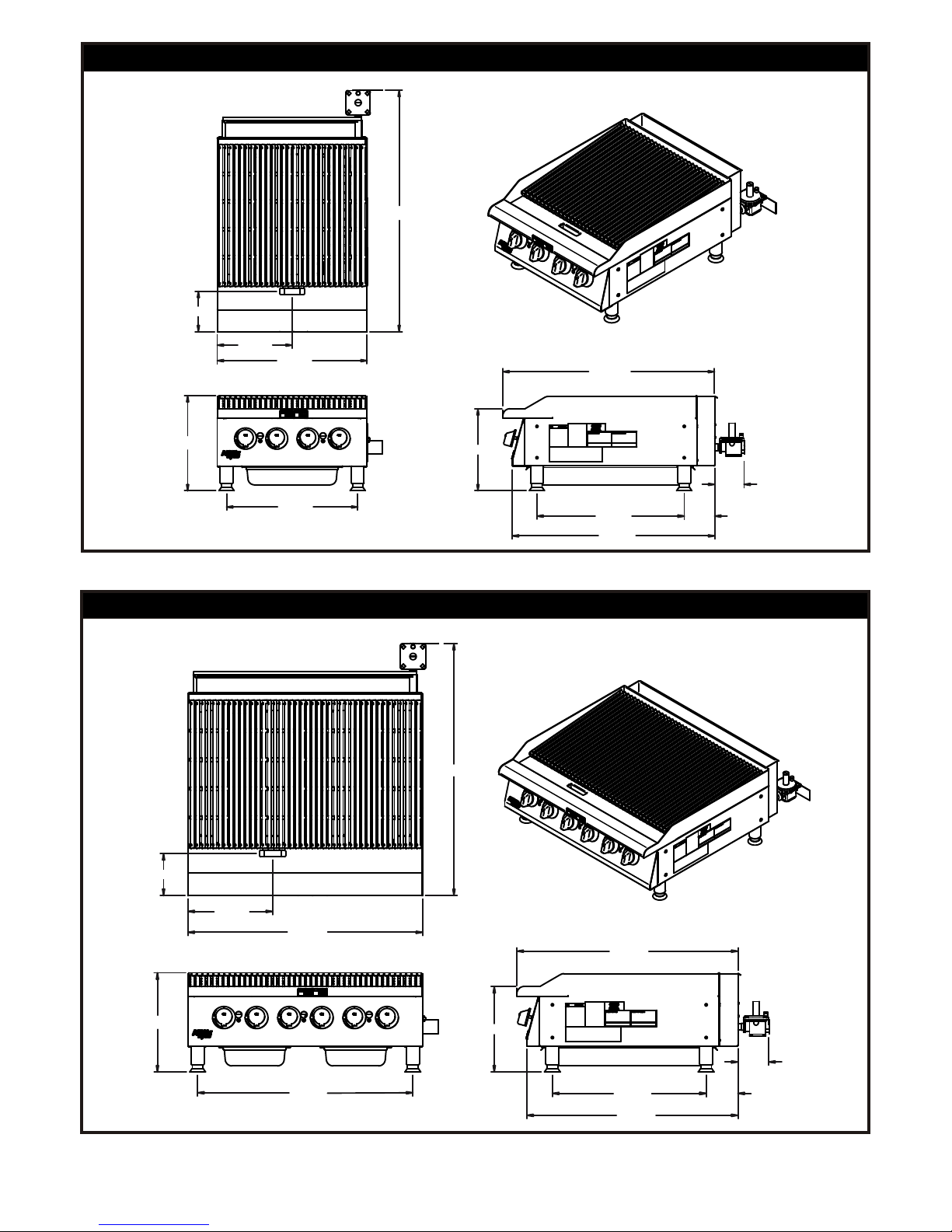
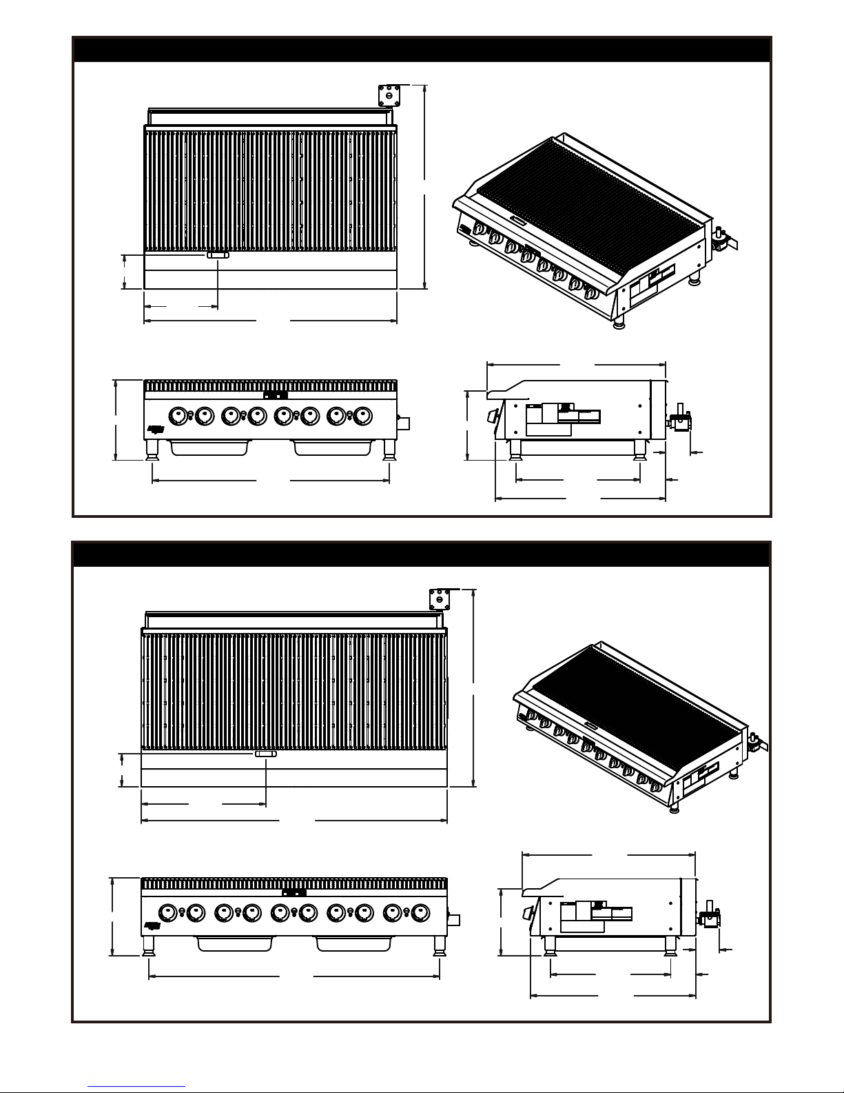
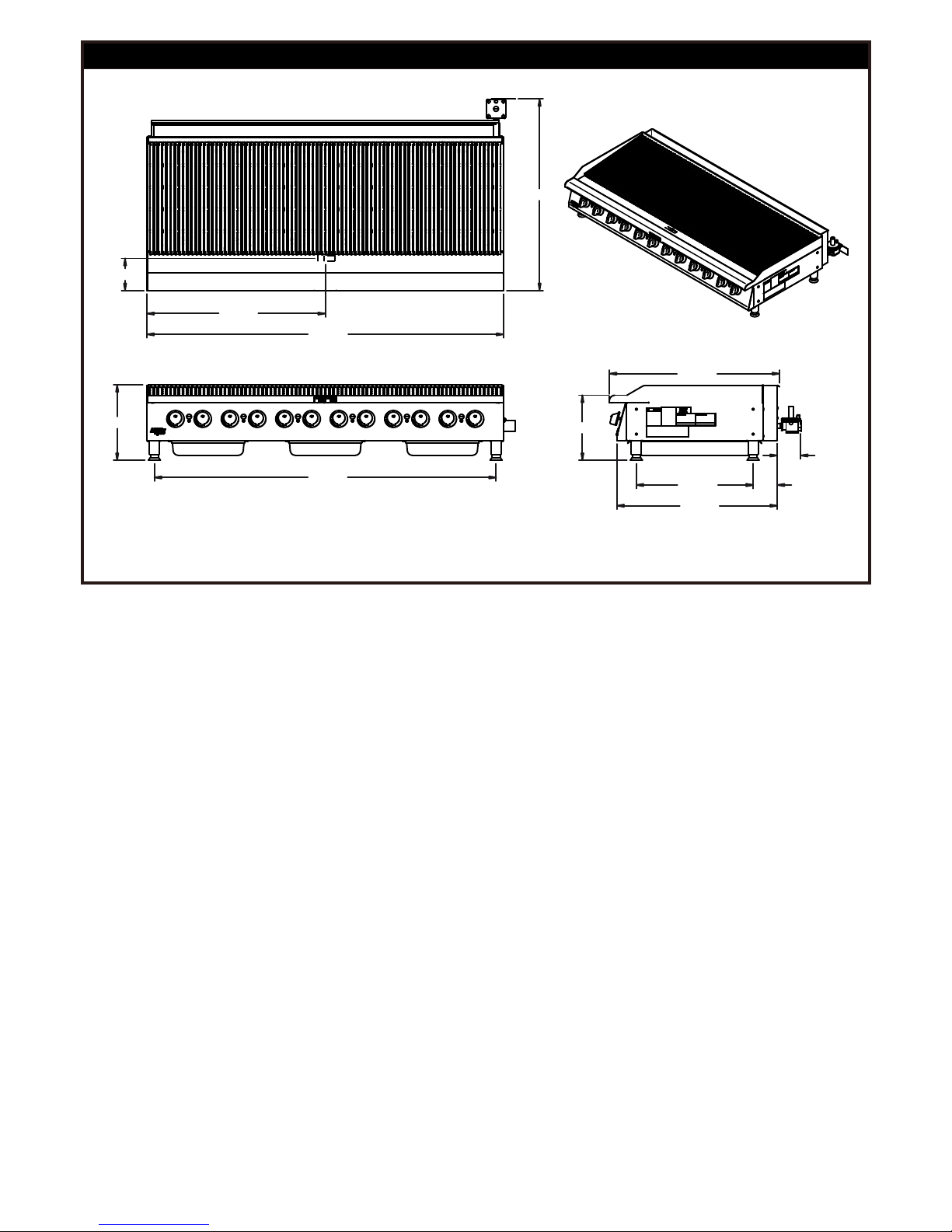
SPECIFICATIONS AND DIMENSIONS
MODEL WIDTH
IN. (MM)
DEPTH
IN. (MM)
HEIGHT
IN. (MM)
# OF
BURNERS
BTU/kW PER
BURNER
NATURAL GAS
TOTAL
BTU/kW HOUR
W.C.
IN. (’Mbar’)
HCB-2424 24" (609.6) 34.339” (872.2) 15.217" (386.5) 4 20,000 (5.86) 80,000 (23.4) 5 (12.4)
HCB-2436 36" (914.4) 34.339” (872.2) 15.217" (386.5) 6 20,000 (5.86) 120,000 (35.2) 5 (12.4)
HCB-2448 48" (1219.2) 34.339” (872.2) 15.217" (386.5) 8 20,000 (5.86) 160,000 (46.9) 5 (12.4)
HCB-2460 60" (1524.0) 34.339” (872.2) 15.217" (386.5) 10 20,000 (5.86) 200,000 (58.6) 5 (12.4)
HCB-2472 72" (1828.8) 34.339” (872.2) 15.217" (386.5) 12 20,000 (5.86) 240,000 (70.3) 5 (12.4)
HCRB-2424 24" (609.6) 34.339” (872.2) 15.217" (386.5) 4 20,000 (5.86) 80,000 (23.4) 5 (12.4)
HCRB-2436 36" (914.4) 34.339” (872.2) 15.217" (386.5) 6 20,000 (5.86) 120,000 (35.2) 5 (12.4)
HCRB-2448 48" (1219.2) 34.339” (872.2) 15.217" (386.5) 8 20,000 (5.86) 160,000 (46.9) 5 (12.4)
HCRB-2460 60" (1524.0) 34.339” (872.2) 15.217" (386.5) 10 20,000 (5.86) 200,000 (58.6) 5 (12.4)
HCRB-2472 72" (1828.8) 34.339” (872.2) 15.217" (386.5) 12 20,000 (5.86) 240,000 (70.3) 5 (12.4)
15.217 13.119
33.875
23.580
4.708
33.000
38.645
36.000
32.379
13.003
6.446
4.875
HCB/HCRB-2436
24.000
15.217 13.119
33.875
23.580
4.708
21.000
38.645
32.379
4.875
12.003
6.446
HCB/HCRB-2424
HCB & HCRB-2424, 24" GAS CHAR BROILER
5
21825000
HCB & HCRB-2436, 36" GAS CHAR BROILER
21825100
60.000
15.217 13.119
33.875
23.580
4.708
57.000
38.645
32.379
24.428
6.446
4.875
HCB/HCRB-2460
48.000
15.217 13.119
33.875
23.580
4.708
45.000
38.645
32.379
HCB/HCRB-2448
14.003
6.446
4.875
HCB & HCRB-2448, 48" GAS CHAR BROILER
6
21825200
HCB & HCRB-2460, 60" GAS CHAR BROILER
21825300
72.000
15.217 13.119
34.339
23.580
4.708
69.000
38.645
32.379
4.875
36.000
6.446
HCB/HCRB-2472
HCB & HCRB-2472, 72" GAS CHAR BROILER
7
21825400
lConnect the regulator to the unit, connect gas and check for leaks. WARNING: Do not use an open
flame to check for leaks.
lCheck the system pressure. With the front panel removed remove the plug
from the manifold.
lPlace a fitting in the plug opening and connect a manometer.
lFor Natural gas the pressure in the manifold should be 5" water column or
12.4 millibar. For LP the pressure in the manifold should be 10" water Column or
24.9 millibar.
lTo adjust the pressure remove the brass cap and turn the white plastic part inside
the stem of the regulator. See picture regulator 8.
lTake a wide straight screw driver and place it in the two notches shown in picture regulator 7 turn
clockwise to increase pressure and counter-clockwise to reduce pressure. See picture regulator 8.
lOnce the pressure has been adjusted replace the brass cap.
lNote the blue cap on the regulator, this is the vent there are openings below the top rim. NEVER
block these openings your regulator will fail to operate correctly. On at least a monthly basis blow off
any dust or grease which may accumulate around this cap. The openings must remain open for the
regulator to function. Clean more often in a very greasy atmosphere.
8
NAT
LP
CONVERSION
lInstructions are for conversion from Natural Gas to Propane (L.P.) on all models HCRB & HCB.
lThe conversion should be done before connecting the unit to the gas supply.
lUnits are shipped from the factory equipped for use on natural gas. Orifices necessary for LP
(propane) are provided in a bag tied to the valve on the front panel.
1. Remove the knobs and front panel.
2. Remove the orifice fittings from the valve. Change the orifices to the size recommended for
propane (L.P.).
3. Replace the orifice fittings into the valve.
lTo change the regulator:
1. Remove brass
cap
2. Locate the plastic
part attached to the
brass cap
3. This is the natural
gas position
4. Snap the plastic
part off of the brass
cap
5. Flip the plastic part
over & snap the
plastic part onto the
brass cap in the
opposite direction
6. Note you can read
LP on the plastic
part it is now in the
LP position
7. Replace the brass
cap back into the
body of the
regulator
8. To adjust pressure:
Remove brass cap &
turn white plastic
part inside the stem
of regulator
9
LIGHTING INSTRUCTIONS
HCB and HCRB Broilers are furnished with either a pilot safety valve or a standing pilot (not available in the
European Community). Please follow the instructions for your unit.
Pilot Operation Flame Failure Gas Valve:
Operation of the gas valve pilot:
1. Turn knob on the main gas valve to the pilot position
2. Depress knob to start gas flow to the pilot valve
3. Light pilot valve
a. Using a match or taper
4. Hold in knob for 15 to 30 seconds to heat up the thermocouple
5. Release knob and turn to the desired gas flow position
a. If pilot goes out repeat steps 1-4, some thermocouples will take longer to heat up
Standing Pilot Lighting Instructions: ( Not Available in the European Community )
The pilot lights on the broilers have been set at the factory. A screwdriver may be required for the first lighting
to adjust the flame for your elevation.
1. Turn off the manual shut off valve and wait 5 minutes to clear the gas.
2. Turn all knobs to the "OFF" position.
3. The valve can be accessed through an opening in the front panel or remove the cooking grates
and light the pilot from above.
4. Turn the manual shut off valve on.
5. Hold an ignition source (match) to both openings on the pilot tube. When the flames are
established, remove the ignition source.
6. Turn the burner knobs to "HI". If the burner does not ignite, promptly open the pilot valve more. If
the pilot flame appears larger than necessary, turn it down and reset burner ignition. The pilot
flame should be as small as possible but large enough to guarantee reliable ignition of the
burners when the knobs are turned to "HI".
RELIGHTING PILOT
If the pilot light should go out for any reason:
lPromptly shut off all gas at the manual shut off valve.
lTurn off all knobs and pilot valves; wait 5 minutes to clear gas.
lRelight following steps 4 through 6 under Standing Pilot Lighting Instructions.
LIGHTING MAIN BURNER:
Since the burner is lit from constantly burning pilot, turn knobs to "HI" to put the unit in operation; then adjust
to any desired position between "LO" and "HI".
lTo light burner, turn knob to "max." then back off to the desired flame level. The range of adjustment is
virtually infinite between high and off. (At the small flame, there is a pre-set low).
lWhen the broiler is first heated, it will smoke until oil used in manufacturing, preservation and dust from
storage and shipping are burned off. An hour at "max." on all burners is usually sufficient.
lTurn knobs off and let cool .
lFor first cooking, set the grates at maximum tilt position and preheat before broiling. You will have to
experiment with knob settings and grate position for each particular item.
lClean regularly. Grates may be removed for washing in the sink. Brush out carbonized particles.
Thoroughly wash the grease/water pan.
CAUTION
Never attempt to move a grill section while cooking. An unexpected flare could cause severe injury. Turn off
the unit, let it cool and use potholders and/or gloves to reposition or remove. The space between the legs at
the bottom admits combustion air. DO NOT BLOCK THIS SPACE.
10
Main burner air supply:
For efficient burner operation, a proper balance of gas volume and primary air supply must be maintained
which will result in complete combustion. Insufficient air supply results in a yellow streaming flame. Primary
air supply is controlled by an air shutter on the front of the burner.
Loosen the screws on the front of the burner, and adjust the air shutter to just eliminate the yellow tips of the
burner flame. Lock the air shutter in place by tightening the screws.
European Community:
If adjustment becomes necessary in the field, it should be done by a factory authorized and trained
technician who should seal the screw after the adjustment to safeguard against unauthorized
tampering by the end user.
All burners are lit from constantly burning pilots. Turning the valve to the desired flame height is all that is
required to put the unit in service.
Do not permit fans to blow directly at the unit. Wherever possible, avoid open windows next to the units'
sides or back. Avoid wall type fans which create air cross-currents within a room.
It is also necessary that sufficient air should be allowed to enter the room to compensate for the amount of air
removed by any ventilating system. Otherwise, a subnormal atmospheric pressure will occur, which will
effect operation and cause undesirable working conditions.
A properly designed and installed hood will act as the heart of the ventilating system for the room or area in
which the unit is installed and will leave the unit independent of changing draft conditions.
All valves must be checked and lubricated periodically. This must be done by an authorized service
representative in your area.
OPERATING INSTRUCTIONS
OPERATION: Turn the burners on about 15-20 minutes before cooking for preheating. Set the knobs to the
desired flame height or temperature. Each valve will control the gas flow to the burner to bring that area of
the unit up to the set temperature. If different temperature settings are to be used, adjoining areas should be
set at progressively higher temperatures using the lowest temperatures on the outside burners. A uniform
and systematic approach to the loading of the unit will produce the most consistent product results.
RADIANTS
Place the radiants in their position as shown in Sketch 1. Make sure that the radiants are setting properly
into the slots on the front and rear supports. Radiants should be centered over straight section of the
burners.
COOKING GRATES
Place the top cooking grates with the grid bars sloping toward the front as shown in Sketch 2.
SEASON GRIDDLE
Heat to low temperature (300 - 350F/150-180C) and pour on a small amount of cooking oil, about one
ounce (30cc) per square foot of surface. Spread the oil over the entire griddle surface with a cloth to create
a thin film. Wipe off any excess oil with a cloth. Repeat this procedure 2 to 3 times until the griddle has a
slick, mirror-like surface.
NOTE: When cooking grates are placed sloping toward the front, the grooves on top will guide the excess
fat drippings into the grease trough. For wider branding marks turn the cooking grate over so the product is
placed on the wider rails. There is less grease removal with the cooking grates in this position so there will be
a little more flare ups in this position.
CAUTION: Do not turn on gas valves without lighting pilots. This could cause a build up of
gas and potential explosion.